Note: Descriptions are shown in the official language in which they were submitted.
CA 02866691 2016-05-10
SYSTEM AND METHOD FOR HANDLING OF AN UPLINK TRANSMISSION
COLLISION WITH AN ACK/NACK SIGNAL
CLAIM OF PRIORITY
[0001] This application claims priority to U.S. Patent Application No.
13/416,618 filed on March 9, 2012.
FIELD
[0002] This disclosure relates to data transmission in wireless
communication
systems, and more particularly, to systems and methods for handling of an
uplink
transmission collision with an acknowledgement (ACK)/negative acknowledgement
(NACK) signal.
BACKGROUND
[0003] In an evolved universal terrestrial radio access network (E-
UTRAN),
new data transmissions or retransmissions may result in the transmission of an
uplink
shared channel (UL-SCH) medium access control (MAC) protocol data unit (PDU)
in
the form of a physical uplink shared channel (PUSCH) transport block. The UL-
SCH
is an uplink transport channel mapped directly to the PUSCH physical channel.
A
physical layer ACK/NACK transmission is used in the E-UTRAN network to provide
feedback information to the transmitter regarding whether a transmitted
downlink
transport block on the Physical Downlink Shared Channel (PDSCH) is
successfully
received or not. Further, an ACK/NACK may be repeatedly transmitted on the
uplink
in consecutive uplink subframes to allow better reception quality at the
receiver side
when the channel conditions are poor.
BRIEF DESCRIPTION OF DRAWINGS
[0004] FIG. 1 is a schematic representation of an example wireless cellular
communication system based on 3GPP long term evolution (LTE).
[0005] FIG. 2 is a schematic block diagram illustrating various layers
of an
access node and user equipment in a wireless communication network according
to
one embodiment.
1
CA 02866691 2014-09-08
WO 2013/134187
PCT/US2013/028991
[0006] FIG. 3 is a schematic block diagram illustrating an access node
device
according to one embodiment.
[0007] FIG. 4 is a schematic block diagram illustrating a user
equipment
device according to one embodiment.
[0008] FIG. 5A is a schematic block diagram illustrating an uplink hybrid
automatic repeat request (HARQ) entity at a user equipment device.
[0009] FIG. 5B is a schematic block diagram illustrating an uplink
HARQ
process at a user equipment device.
[0010] FIG. 6 is a schematic timing diagram illustrating a synchronous
uplink
HARQ operation at a user equipment device.
[0011] FIG. 7 is a process flow chart illustrating a method for
handling an
uplink transmission collision with an ACK/NACK signal by a physical layer at a
user
equipment device.
[0012] FIG. 8 is a process flow chart illustrating a method for
handling an
uplink transmission collision with an ACK/NACK signal by a MAC layer at a user
equipment device.
[0013] FIG. 9 is a process flow chart illustrating an alternative
method for
handling an uplink transmission collision with an ACK/NACK signal by a MAC
layer
at a user equipment device.
[0014] Like reference symbols in the various drawings indicate like
elements.
DETAILED DESCRIPTION
[0015] The following detailed description presents various embodiments
of the
present disclosure. However, the present disclosure is intended to provide a
multitude
of different ways as defined and covered by the claims. In this description,
reference
is made to the drawings where like reference numerals indicate like or
functionally
similar elements.
[0016] The terminology used in the description presented herein is not
intended to be interpreted in any limited or restrictive manner, simply
because it is
being utilized in conjunction with a detailed description of certain specific
embodiments of the disclosure. Furthermore, embodiments of the disclosure may
include several novel features, no single one of which is solely responsible
for its
desirable attributes or which is essential to practicing the disclosure herein
described.
2
CA 02866691 2014-09-08
WO 2013/134187
PCT/US2013/028991
[0017] Embodiments are described herein in the context of an LTE
wireless
network or system, but can be adapted for other wireless networks or systems.
The
LTE wireless network described herein is generally in compliance with the 3GPP
LTE
standard, including, but not limited to, Releases 8, Release 9, Release 10,
Release 11,
and beyond.
[0018] As used herein, the terms "user equipment" and "UE" can refer
to
wireless devices and similar devices or other User Agents ("UA") that have
telecommunications capabilities. In some embodiments, a UE may refer to a
mobile,
wireless device. The term "UE" may also refer to devices that have similar
capabilities, but that are not generally transportable, such as desktop
computers or set-
top boxes.
[0019] Examples of user equipment include, but are not limited to, a
mobile
phone, a smart phone, a telephone, a television, a remote controller, a set-
top box, a
computer monitor, a computer (including a tablet computer such as a
BlackBerry0
Playbook tablet, a desktop computer, a handheld or laptop computer, a netbook
computer), a personal digital assistant (PDA), a microwave, a refrigerator, a
stereo
system, a cassette recorder or player, a DVD player or recorder, a CD player
or
recorder, a VCR, an MP3 player, a radio, a camcorder, a camera, a digital
camera, a
portable memory chip, a washer, a dryer, a washer/dryer, a copier, a facsimile
machine, a scanner, a multi-functional peripheral device, a wristwatch, a
clock, and a
game device, Such a UE might include a device and its associated removable
memory
module, such as a Universal Integrated Circuit Card (UICC) that includes a
Subscriber
Identity Module (SIM) application, a Universal Subscriber Identity Module
(USIM)
application, or a Removable User Identity Module (R-UIM) application.
Alternatively, such a UE might include the device itself without such a
module. The
term "UE" can also refer to any hardware or software component that can
terminate a
communication session for a user. In addition, the terms "user equipment,"
"UE,"
"user equipment device," "user agent," "UA," "user device," and "mobile
device" can
be used synonymously herein.
[0020] In traditional wireless telecommunications systems, transmission
equipment in a base station or other network node transmits signals throughout
a
geographical region known as a cell. As technology has evolved, more advanced
equipment has been introduced that can provide services that were not possible
3
CA 02866691 2014-09-08
WO 2013/134187
PCT/US2013/028991
previously. This advanced equipment might include, for example, an E-UTRAN
evolved Node B (eNB) rather than a base station or other systems and devices
that are
more highly evolved than the equivalent equipment in a traditional wireless
telecommunications system. In the context of this document, the term "eNB" can
be
interchangeably used with an "evolved node B" or an "enhanced node B." Such
advanced or next generation equipment may be referred to herein as long-term
evolution (LTE) equipment, and a packet-based network that uses such equipment
can
be referred to as an evolved packet system (EPS). Additional improvements to
LTE
systems and equipment result in an LTE Advanced (LTE-A) system. As used
herein,
the phrase "base station" may refer to any component or network node, such as
a
traditional base station or an LTE or LTE-A base station (including eNBs),
that can
provide a UE with access to other components in a telecommunications system.
[0021] The present disclosure pertains to systems and methods for
handling of
an uplink transmission collision with an ACK/NACK signal. The collision may
occur
when a UE is configured to transmit a physical shared channel (PUSCH)
transmission
and an ACK/NACK signal at the same subframe.
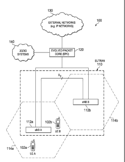
[0022] FIG. 1 is a schematic representation of an example wireless
cellular
communication system 100 based on the third generation partnership project
(3GPP)
LTE, also known as Evolved Universal Terrestrial Radio Access (E-UTRA). The
cellular network system 100 shown in FIG. 1 includes a plurality of base
stations 112a
and 112b. In the LTE example of FIG. 1, the base stations are shown as evolved
Node
Bs (eNBs) 112a and 112b. It will be understood that the base station may
operate in
any mobile environment, including macro cell, femto cell, pico cell, or the
base station
may operate as a node that can relay signals for other mobile and/or base
stations. The
example LTE telecommunications environment 100 of FIG. 1 may include one or a
plurality of radio access networks 110, core networks (CNs) 120, and external
networks 130. In certain implementations, the radio access networks may be E-
UTRANs. In addition, in certain instances, core networks 120 may be evolved
packet
cores (EPCs). Further, there may be one or more mobile electronic devices
102a, 102b
operating within the LTE system 100. In some implementations, 2G/3G systems
140,
e.g., Global System for Mobile communication (GSM), Interim Standard 95 (IS-
95),
Universal Mobile Telecommunications System (UMTS) and CDMA2000 (Code
4
CA 02866691 2014-09-08
WO 2013/134187
PCT/US2013/028991
Division Multiple Access) may also be integrated into the LTE
telecommunication
system 100.
[0023] In the example LTE system shown in FIG. 1, the EUTRAN 110
includes eNB 112a and eNB 112b. Cell 114a is the service area of eNB 112a and
Cell
114b is the service area of eNB 112b. UEs 102a and 102b operate in Cell 114a
and are
served by eNB 112a. The EUTRAN 110 can include one or a plurality of eNBs
112a,
112b and one or a plurality of UEs 102a, 102b can operate in a cell. The eNBs
112a
and 112b communicate directly to the UEs 102a and 102b. In some
implementations,
the eNB 112a or 112b may be in a one-to-many relationship with the UEs 102a
and
102b, e.g., eNB 112a in the example LTE system 100 can serve multiple UEs 102
(i.e.,
UE 102a and UE 102b) within its coverage area Cell 114a, but each of UE 102a
and
UE 102b may be connected only to one eNB 112a at a time. In some
implementations,
the eNBs 112a and 112b may be in a many-to-many relationship with the UEs,
e.g.,
UE 102a and UE 102b can be connected to eNB 112a and eNB 112b. The eNB 112a
may be connected to eNB 112b with which handover may be conducted if one or
both
of the UEs 102a and UE 102b travels from cell 114a to cell 114b. The UEs 102a
and
102b may be any wireless electronic device used by an end-user to communicate,
for
example, within the LTE system 100. The UE 102a or 102b may be referred to as
mobile electronic device, user device, mobile station, subscriber station, or
wireless
terminal. The UE 102a or 102b may be a cellular phone, personal data assistant
(PDA), smart phone, laptop, tablet personal computer (PC), pager, portable
computer,
or other wireless communications device.
[0024] The UEs 102a and 102b may transmit voice, video, multimedia,
text,
web content and/or any other user/client-specific content. On the one hand,
the
transmission of some of these contents, e.g., video and web content, may
require high
channel throughput to satisfy the end-user demand. On the other hand, the
channel
between UEs 102a, 102b and eNBs 112a, 112b may be contaminated by multipath
fading, due to the multiple signal paths arising from many reflections in the
wireless
environment. Accordingly, the UEs' transmission may adapt to the wireless
environment. In short, the UEs 102a and 102b generate requests, send responses
or
otherwise communicate in different means with Evolved Packet Core (EPC) 120
and/or Internet Protocol (IP) networks 130 through one or more eNBs 112a and
112b.
5
CA 02866691 2014-09-08
WO 2013/134187
PCT/US2013/028991
[0025] A radio access network is part of a mobile telecommunication
system
which implements a radio access technology, such as UMTS, CDMA2000 and 3GPP
LTE. In many applications, the Radio Access Network (RAN) included in an LTE
telecommunications system 100 is called an EUTRAN 110. The EUTRAN 110 can be
located between the UEs 102a, 102b and EPC 120. The EUTRAN 110 includes at
least one eNB 112a or 112b. The eNB can be a radio base station that may
control all
or at least some radio related functions in a fixed part of the system. The at
least one
eNB 112a or 112b can provide radio interface within their coverage area or a
cell for
the UEs 102a, 102b to communicate. The eNBs 112a and 112b may be distributed
throughout the cellular network to provide a wide area of coverage. The eNBs
112a
and 112b directly communicate with one or a plurality of UEs 102a, 102b, other
eNBs,
and the EPC 120.
[0026] The eNBs 112a and 112b may be the end point of the radio
protocols
towards the UEs 102a, 102b and may relay signals between the radio connection
and
the connectivity towards the EPC 120. In certain implementations, the EPC 120
is the
main component of a core network (CN). The CN can be a backbone network, which
may be a central part of the telecommunications system. The EPC 120 can
include a
mobility management entity (MME), a serving gateway (SGW), and a packet data
network gateway (PGW). The MME may be the main control element in the EPC 120
responsible for the functionalities comprising the control plane functions
related to
subscriber and session management. The SGW can serve as a local mobility
anchor,
such that the packets are routed through this point for intra EUTRAN 110
mobility and
mobility with other legacy 2G/ 3G systems 140. The SGW functions may include
the
user plane tunnel management and switching. The PGW may provide connectivity
to
the services domain comprising external networks 130, such as the IP networks.
The
UEs 102a, 102b, EUTRAN 110, and EPC 120 are sometimes referred to as the
evolved
packet system (EPS). It is to be understood that the architectural evolvement
of the
LTE system 100 is focused on the EPS. The functional evolution may include
both
EPS and external networks 130.
[0027] Though described in terms of FIG. 1, the present disclosure is not
limited to such an environment. In general, cellular telecommunication systems
may
be described as cellular networks made up of a number of radio cells, or cells
that are
each served by a base station or other fixed transceiver. The cells are used
to cover
6
CA 02866691 2014-09-08
WO 2013/134187
PCT/US2013/028991
different areas in order to provide radio coverage over an area. Example
cellular
telecommunication systems include Global System for Mobile Communication (GSM)
protocols, Universal Mobile Telecommunications System (UMTS), 3GPP Long Term
Evolution (LTE), and others. In addition to cellular telecommunication
systems,
wireless broadband communication systems may also be suitable for the various
implementations described in the present disclosure. Example wireless
broadband
communication systems include IEEE 802.11 wireless local area network, IEEE
802.16 WiMAX network, etc.
[0028] FIG. 2 is a schematic block diagram 200 illustrating various
layers of an
access node and user equipment in a wireless communication network according
to
one embodiment. The illustrated system 200 includes a UE 205 and an eNB 215.
The
eNB 215 can be referred to as a "network," "network component," "network
element,"
"access node," or "access device." FIG. 2 shows only these two devices
(alternatively,
referred to as "apparatuses" or "entities") for illustrative purposes, and a
skilled artisan
will appreciate that the system 200 can further include one or more of such
devices,
depending on the needs. The eNB 215 can communicate wirelessly with the UE
205.
[0029] Each of the devices 205 and 215 includes a protocol stack for
communications with other devices via wireless and/or wired connection. The UE
205
can include a physical (PHY) layer 202, a medium access control (MAC) layer
204, a
radio link control (RLC) layer 206, a packet data convergence protocol (PDCP)
layer
208, a radio resource control (RRC) layer 210, and a non-access stratum (NAS)
layer
212. The UE 205 may also include one or more antennas 214 coupled to the PHY
layer 202. In the illustrated embodiment, a "PHY layer" can also be referred
to as
"layer 1." The other layers (MAC layer, RLC layer, PDCP layer, RRC layer and
above) can be collectively referred to as a "higher layer(s)."
[0030] The eNB 215 can also include a physical (PHY) layer 216, a
medium
access control (MAC) layer 218, a radio link control (RLC) layer 220, a packet
data
convergence protocol (PDCP) layer 222, and a radio resource control (RRC)
layer 224.
In case of user plane communication for data traffic, the RRC layer is not
involved.
The eNB 215 may also include one or more antennas 226 coupled to the PHY layer
216.
[0031] Communications between the devices, such as between the eNB 215
and the UE 205, generally occur within the same protocol layer between the two
7
CA 02866691 2014-09-08
WO 2013/134187
PCT/US2013/028991
devices. Thus, for example, communications from the RRC layer 224 at the eNB
215
travel through the PDCP layer 222, the RLC layer 220, the MAC layer 218, and
the
PHY layer 216, and are sent over the PHY layer 216 and the antenna 226 to the
UE
205. When received at the antenna 214 of the UE 205, the communications travel
through the PHY layer 202, the MAC layer 204, the RLC layer 206, the PDCP
layer
208 to the RRC layer 210 of the UE 205. Such communications are generally done
utilizing a communications sub-system and a processor, as described in more
detail
below.
[0032] FIG. 3 is a schematic block diagram 300 illustrating an access
node
device according to one embodiment. The illustrated device 300 includes a
processing
module 302, a wired communication subsystem 304, and a wireless communication
subsystem 306. The processing module 302 can include one or more processing
components (alternatively referred to as "processors" or "central processing
units"
(CPUs)) capable of executing instructions related to one or more of the
processes,
steps, or actions described above in connection with one or more of the
embodiments
disclosed herein. The processing module 302 can also include other auxiliary
components, such as random access memory (RAM), read only memory (ROM),
secondary storage (for example, a hard disk drive or flash memory). The
processing
module 302 can form at least part of the layers described above in connection
with
FIG. 2. The processing module 302 can execute certain instructions and
commands to
provide wireless or wired communication, using the wired communication
subsystem
304 or a wireless communication subsystem 306. A skilled artisan will readily
appreciate that various other components can also be included in the device
300.
[0033] FIG. 4 is a schematic block diagram 400 illustrating a user
equipment
device according to one embodiment. The illustrated device 400 includes a
processing
unit 402, a computer readable storage medium 404 (for example, ROM or flash
memory), a wireless communication subsystem 406, a user interface 408, and an
I/0
interface 410.
[0034] Similar to the processing module 302 of FIG. 3, the processing
unit 402
can include one or more processing components (alternatively referred to as
"processors" or "central processing units" (CPUs)) configured to execute
instructions
related to one or more of the processes, steps, or actions described above in
connection
with one or more of the embodiments disclosed herein. The processing unit 402
can
8
CA 02866691 2014-09-08
WO 2013/134187
PCT/US2013/028991
also include other auxiliary components, such as random access memory (RAM)
and
read only memory (ROM). The computer readable storage medium 404 can store an
operating system (OS) of the device 400 and various other computer executable
software programs for performing one or more of the processes, steps, or
actions
described above.
[0035] The
wireless communication subsystem 406 is configured to provide
wireless communication for data and/or control information provided by the
processing unit 402. The wireless communication subsystem 406 can include, for
example, one or more antennas, a receiver, a transmitter, a local oscillator,
a mixer,
and a digital signal processing (DSP) unit. In some embodiments, the subsystem
406
can support multiple input multiple output (MIMO) transmissions.
[0036] The user
interface 408 can include, for example, one or more of a
screen or touch screen (for example, a liquid crystal display (LCD), a light
emitting
display (LED), an organic light emitting display (OLED), a
microelectromechanical
system (MEMS) display), a keyboard or keypad, a trackball, a speaker, and a
microphone. The I/0 interface 410 can include, for example, a universal serial
bus
(USB) interface. A skilled artisan will readily appreciate that various
other
components can also be included in the device 400.
[0037] FIG. 5A
is a schematic block diagram illustrating an uplink (UL) hybrid
automatic repeat request (HARQ) entity at a user equipment device 500. As
shown in
FIG. 5A, an uplink HARQ entity 508 maintains a number of parallel uplink HARQ
processes 510-514 allowing uplink transmissions to take place continuously
while
waiting for the HARQ feedback on the successful or unsuccessful reception of
previous transmissions. A resource assignments and ACK/NACK status entity 504
may inform the uplink HARQ entity 508 about uplink transmission resource
assignments and the received ACK/NACK status from the physical layer 202
(shown
in FIG. 2). The uplink HARQ entity 508 may interact with a multiplexing and
assembly entity 502 at the UE to obtain a MAC protocol data unit (PDU) for
transmission from the multiplexing and assembly entity 502. The uplink HARQ
entity
508 may instruct a data for transmission entity 506 to generate a new
transmission, an
adaptive retransmission, or a non-adaptive retransmission after receiving
resource
assignments, or ACK/NACK notification from the resource assignments and
ACK/NACK status entity 504. The uplink HARQ entity 508, multiplexing and
9
CA 02866691 2014-09-08
WO 2013/134187
PCT/US2013/028991
assembly entity 502, and the HARQ processes 510-514 may be located at a MAC
layer
204 of the user equipment device (shown in FIG. 2). The resource assignments
and
ACK/NACK status entity 504 and data for transmission entity 506 may be located
at a
physical layer 202 of the user equipment device (shown in FIG. 2). Although 8
uplink
HARQ processes (510, 512, 514) are shown in FIG. 5A, this is illustrative only
and
more or fewer than 8 uplink HARQ processes may be present.
[0038] FIG. 5B is a schematic block diagram illustrating the uplink
HARQ
process module 510. The uplink HARQ process module 510 may be located at a
MAC layer 204 of the user equipment device. The illustrated uplink HARQ
process
module 510 includes an uplink transmission buffer 516 and various uplink HARQ
parameters 518. The uplink HARQ transmission buffer 516 stores the information
bits
which are transmitted. It may also be referred to as an HARQ buffer. The
uplink
HARQ parameters 518 may include various transmission parameters such as
transport
block size, new data indicator (NDI) flag, modulation and coding scheme (MCS),
resource block allocation, frequency hopping parameters, demodulation
reference
signal (DMRS) cyclic shift, and number of transmission attempts, etc.
[0039] FIG. 6 is a schematic timing diagram 600 illustrating a
synchronous
uplink HARQ operation at a user equipment device. In an E-UTRA network, uplink
HARQ transmission is synchronous in nature. That is, the uplink HARQ process
index
associated with a particular transmission time interval (TTI) is a function of
the TTI
value and is not explicitly signaled from the eNB to the UE in any
(re)transmission
instructions. In normal uplink HARQ operations, each of eight uplink HARQ
processes has a transmission opportunity occurring every 8ms (or every 8
subframes,
with each subframe being 1 ms in length) for a frequency division duplexing
(FDD)
system. The uplink HARQ entity can use the current frame and subframe indices
to
determine which uplink HARQ process is associated with the current TTI. As
shown
in FIG. 6, each sub-block 602-620 represents a subframe and the subframe index
is
indicated in the center of each sub-block. As an example, a new uplink
transmission
622 for uplink process 0 may occur at subframe 0 (shown as sub-block 602). The
uplink HARQ ACK/NACK feedback 624 from the eNB for uplink HARQ process 0
arrives at 4 subframes after the initial new uplink transmission 622. If the
new uplink
transmission 622 is not received correctly at the eNB, i.e., a NACK is
received at
subframe 4 (shown as sub-block 610), a retransmission 626 for uplink HARQ
process
CA 02866691 2014-09-08
WO 2013/134187
PCT/US2013/028991
0 can occur at subframe 8 (shown as sub-block 618), which is 8 subframes after
the
initial transmission 622 at subframe O. If an ACK is received at subframe 4,
the UE
would consider that the new uplink transmission 622 is received successfully
at the
eNB and will not conduct subsequent non-adaptive retransmissions.
[0040] The timing relationships shown in FIG. 6 are illustrative of an
EUTRA
frequency division duplexing (FDD) system. The exact timing relationships for
uplink
HARQ operation in an EUTRA time division duplexing (TDD) system may be
different, but are still synchronous in that uplink HARQ process indices are
not
explicitly signaled but can be derived from the relative timing of the
relevant control
signaling.
[0041] At each transmission opportunity, the uplink HARQ process
associated
with that transmission opportunity may be instructed by the uplink HARQ entity
to
perform one of the following actions: a new data transmission, an adaptive
retransmission, a non-adaptive retransmission, or nothing. A new data
transmission
may be ordered by reception of an uplink grant on the physical downlink
control
channel (PDCCH), by reception of an uplink grant in a Random Access Response
(RAR), or by an uplink grant being generated from a configured UL Semi-
Persistent
Scheduling (UL SPS) grant. An adaptive retransmission may be ordered via
reception
of an appropriately configured downlink control information (DCI) 0 on the
PDCCH
for the uplink HARQ process. An adaptive retransmission may be performed with
different physical resources and/or parameters (signaled via the DCI 0) from
the most
recent transmission for the same transport block. A non-adaptive
retransmission may
be ordered via reception of a NACK on the physical HARQ indicator channel
(PHICH) for the preceding transmission opportunity for the same uplink HARQ
process. A non-adaptive retransmission is performed with the same frequency
resources and MCS as the most recent transmission for the same transport
block, but
with a different HARQ redundancy version. The HARQ redundancy version may be
0,
1, 2, or 3. Nothing occurs if the transmission buffer of the uplink HARQ
process is
empty or if the current HARQ feedback for that uplink HARQ process is
considered to
be an ACK.
[0042] In this disclosure, new data transmissions, adaptive
retransmissions, and
non-adaptive retransmissions may all be referred to as uplink transmissions,
and each
one results in an uplink transmission of an UL-SCH MAC PDU in the form of a
11
CA 02866691 2014-09-08
WO 2013/134187
PCT/US2013/028991
PUSCH transport block. The UL-SCH is an uplink transport channel which is
mapped
directly to the PUSCH physical channel.
[0043] When a downlink (DL) transport block is received on a physical
downlink shared channel (PDSCH) for a UE, the UE will signal a corresponding
ACK
(i.e., the PDSCH transport block was successfully decoded) or NACK (i.e., the
PDSCH transport block was not successfully decoded) on the uplink. This is
normally
accomplished in one of two ways. If a PUSCH transmission is being made in the
same
subframe, then the encoded downlink ACK/NACK information is punctured into
that
PUSCH transmission. If there is no PUSCH transmission being made in the same
subframe, then the downlink ACK/NACK information is signaled via the physical
uplink control channel (PUCCH). If a UE has a poor transmission channel or
otherwise challenging channel conditions between itself and its serving eNB,
then the
eNB may configure that UE with ACK/NACK repetition. When the UE is configured
with ACK/NACK repetition, an ACK/NACK transmitted on the uplink in response to
a downlink reception on the PDSCH is repeated multiple times, for example, 2,
4, or 6
times (depending upon the configured repetition factor) in consecutive uplink
subframes. The ACK/NACK signal which is part of an ACK/NACK repetition
sequence is transmitted on an appropriate PUCCH resource. Collisions may occur
when an uplink transmission is scheduled at the same subframe as part of the
ACK/NACK repetition sequence is scheduled to transmit. Because the UE is not
allowed to multiplex the ACK/NACK repetition sequence with the uplink
transmission
into a PUSCH transmission, the scheduled uplink transmission is refrained and
the
ACK/NACK signal will be transmitted on PUCCH when collisions occur. The eNB
may identify that the scheduled uplink transmission for the UE collides with
the
ACK/NACK signal from the UE and thus refrain from decoding the scheduled
uplink
transmission. Since the scheduled PUSCH transmission is never actually made,
the
UE's physical layer does not attempt to receive uplink HARQ ACK/NACK on
PHICH. The HARQ_FEEDBACK state variable of the corresponding uplink HARQ
process consequently remains set at NACK. Unless a DCI 0 for the next
transmission
opportunity for the uplink HARQ process is received, this NACK value of
HARQ_FEEDBACK will automatically trigger a non-adaptive retransmission which
may not be expected by the eNB. In certain situations, the eNB may have
allocated
those uplink resources elsewhere and the unexpected non-adaptive
retransmission by
12
CA 02866691 2014-09-08
WO 2013/134187
PCT/US2013/028991
the first UE may cause uplink interference to uplink transmissions by other
UEs. This
may degrade the uplink system throughput which is undesirable. Embodiments to
avoid the unexpected uplink non-adaptive retransmission are described in this
disclosure such that potential uplink interference caused by the unexpected
non-
adaptive retransmissions is reduced.
[0044] FIG. 7 is a process flowchart 700 illustrating a method for
handling an
uplink transmission collision with an ACK/NACK signal by a physical layer at a
user
equipment device. As shown in FIG. 7, for a downlink subframe i, a UE checks
whether a PUSCH transport block was transmitted in associated uplink subframe
at
step 702. In an EUTRA FDD system, the associated uplink subframe occurs 4
subframes earlier than the downlink subframe i. For example, if the downlink
subframe index i is 6, the associated uplink subframe would be subframe 2
within the
same radio frame. For an EUTRA TDD system, the relative timing offset between
a
downlink subframe and the associated uplink subframe may be different than for
an
EUTRA FDD system, but this relative timing offset is known by the user
equipment
device. If a PUSCH transport block was transmitted in the associated uplink
subframe,
the UE further checks whether an ACK is decoded on PHICH at step 704. If an
ACK
is decoded, the physical layer delivers the ACK for the PUSCH transport block
to
higher layers at step 706. Specifically, the higher layers may include a MAC
layer 204
at the UE (shown in FIG. 2). If there is no ACK decoded on PHICH, the UE
checks
whether the PUSCH transport block was disabled by PDCCH at step 708. If the
transport block was disabled by PDCCH, the physical layer delivers an ACK for
that
transport block at step 706. Otherwise, if the transport block is not disabled
by
PDCCH, the physical layer delivers a NACK for that transport block to higher
layers
at step 710.
[0045] Steps 704-710 occur when a PUSCH transport block was
transmitted in
the associated uplink subframe. If there was an uplink transmission collision
with an
ACK/NACK signal for the associated uplink subframe, no PUSCH transport block
would be transmitted in the associated uplink subframe and the UE would not
follow
steps 704-710. Instead, the UE checks whether an ACK/NACK repetition is
configured at step 712. If the ACK/NACK repetition is not configured, the
physical
layer would not deliver any ACK or NACK to high layers and the uplink HARQ
feedback processing for this particular downlink subframe i is completed. If
the
13
CA 02866691 2014-09-08
WO 2013/134187
PCT/US2013/028991
ACK/NACK repetition is configured at the UE, the UE continues to check whether
a
TTI bundling is configured at step 714. In normal operation when TTI bundling
is not
configured, a transmission opportunity is a single 1 ms subframe and is
associated with
a single transport block. When TTI bundling is configured, a transmission
opportunity
is a set of multiple consecutive uplink subframes, e.g., 4 consecutive uplink
subframes.
If TTI bundling is configured, the UE checks whether all transport blocks of
the TTI
bundle collided with the ACK/NACK repetition sequence at step 716. If there is
no
collision or only partial collision between the transport blocks of the TTI
bundle and
the ACK/NACK signals, the physical layer would not deliver any ACK or NACK to
higher layers and the uplink HARQ feedback processing for this particular
downlink
subframe i is completed. However, if all transport blocks of the TTI bundle
collided
with ACK/NACK signals, the physical layer would deliver an ACK for that
transport
block to higher layers at step 718. By delivering an ACK to the higher layers
at step
718, the higher layers would consider that the eNB does not wish a non-
adaptive
retransmission of the PUSCH transport block at the current time and thereby
subsequent non-adaptive retransmission for the PUSCH transport block is
refrained.
On the other hand, because the UE would not perform any subsequent non-
adaptive
retransmission for the PUSCH transport block, the eNB may refrain from
decoding the
scheduled uplink transmission. The eNB can allocate the uplink resources for
other
UEs. The eNB may order an adaptive retransmission for the PUSCH transport
block
such that the UE would transmit the PUSCH transport block using resources
allocated
for the adaptive retransmission.
[0046] If the TTI bundling is not configured, the UE would check
whether the
scheduled PUSCH transport block in the associated uplink subframe collided
with an
ACK/NACK signal at step 720. The ACK/NACK signal may be part of an
ACK/NACK repetition sequence. If there was a collision between the PUSCH
transport block and the ACK/NACK signal, the physical layer would deliver an
ACK
for that transport block to higher layers at step 718. By delivering an ACK to
the
higher layers at step 718, the higher layers would consider that the eNB does
not wish
a non-adaptive retransmission of the PUSCH transport block at the current time
and
thereby subsequent non-adaptive retransmission for the PUSCH transport block
is
refrained. If there was no collision, the physical layer would not deliver any
ACK or
14
CA 02866691 2014-09-08
WO 2013/134187
PCT/US2013/028991
NACK to higher layers and the uplink HARQ feedback processing for this
particular
downlink subframe i is completed.
[0047] FIG. 8
is a process flowchart 800 illustrating a method for handling an
uplink transmission collision with an ACK/NACK signal by a MAC layer at a user
equipment device. As shown in FIG. 8, for an uplink subframe j, the MAC layer
HARQ process first checks whether a measurement gap occurs at a time of a
scheduled transmission at step 802. A UE may need to make measurements of
other
cells which either are E-UTRA but which operate on a different frequency band
or
which belong to a different radio access technology (RAT) completely. Most UEs
only have one radio for receiving, and hence must tune away this radio from
the
operating frequency band of its serving cell in order to make inter-frequency
and/or
inter-RAT measurements. In order to facilitate this, an eNB may configure a UE
with
measurement gaps, during which the UE is allowed to tune away from the
operating
frequency band of its serving cell. Consequently, a UE cannot receive from nor
transmit to the serving cell during a configured measurement gap. If a
measurement
gap occurs at the time of a scheduled transmission, the transmission does not
take
place. Otherwise, the MAC layer HARQ process instructs the physical layer to
generate a transmission at step 804 and increments the current redundancy
version
index by 1 at step 806. The transmission at step 804 may be an uplink
transmission for
new data, an uplink non-adaptive retransmission, or an uplink adaptive
retransmission
on the UL-SCH or PUSCH.
[0048] After
incrementing the redundancy version index at step 806, the MAC
layer HARQ process checks whether a measurement gap occurs at the time of HARQ
feedback reception corresponding to the uplink transmission at step 808. If
a
measurement gap occurs at the time of HARQ feedback reception, the UE would
not
be able to receive the HARQ feedback. As a result, the MAC layer HARQ process
would consider that the eNB does not wish a non-adaptive retransmission of the
PUSCH transport block at the current time and set HARQ feedback to ACK at step
816. If no measurement gap occurs at the time of HARQ feedback reception, the
MAC layer HARQ process checks whether an ACK/NACK repetition is configured at
the UE at step 810. If no ACK/NACK repetition is configured, the HARQ feedback
received from the physical layer would not be changed. If an ACK/NACK
repetition
is configured, the MAC layer further checks whether a TTI bundling is
configured at
CA 02866691 2014-09-08
WO 2013/134187
PCT/US2013/028991
step 812. If TTI bundling is configured, the MAC layer checks whether all
transmissions of the TTI bundle collide with the transmission of an ACK/NACK
signal belonging to an ACK/NACK repetition sequence at step 818. If no
collision or
only partial collision between the transmissions of the TTI bundle and the
ACK/NACK signals is identified, the MAC layer HARQ process would not set the
HARQ feedback value. If all transmissions of the TTI bundle collide with
ACK/NACK transmissions, the transmission of the TTI bundle would be refrained
and
the MAC layer HARQ process would set HARQ feedback to ACK at step 816. The
ACK/NACK transmissions colliding with the transmissions of the TTI bundle may
belong to the same ACK/NACK repetition sequence or multiple different ACK/NACK
repetition sequences. Consequently, subsequent non-adaptive retransmissions
for the
uplink transmission at step 804 are refrained at the UE.
[0049] If the TTI bundling is not configured, the UE would check
whether the
UL-SCH transmission at step 804 collides with an ACK/NACK transmission at step
814. The ACK/NACK transmission may be an ACK/NACK signal that is part of an
ACK/NACK repetition sequence. If the UL-SCH transmission collides with an
ACK/NACK transmission, the scheduled UL-SCH transmission would be refrained
and the MAC layer HARQ process would set the HARQ feedback to ACK at step 816.
Non-adaptive retransmissions for the scheduled UL-SCH transmission would be
refrained as a result. If no collision is identified between the scheduled UL-
SCH and
the ACK/NACK transmission, the MAC layer HARQ process would not set the
HARQ feedback value for the scheduled UL-SCH transmission at this instance.
The
eNB may identify that a scheduled UL-SCH transmission for the UE collides with
the
ACK/NACK transmission and correspondingly choose to refrain from decoding the
scheduled UL-SCH transmission. Furthermore, the eNB may identify that a
scheduled
UL-SCH transmission for the UE collides with the ACK/NACK transmission and
correspondingly choose to refrain from decoding a subsequent non-adaptive
retransmission for the scheduled UL-SCH if there is a collision between the
scheduled
UL-SCH transmission and the ACK/NACK transmission. The eNB may order a
subsequent adaptive retransmission for the scheduled UL-SCH to request the UE
to
transmit the scheduled UL-SCH.
[0050] FIG. 9 is a process flowchart 900 illustrating an alternative
method for
handling an uplink transmission collision with an ACK/NACK signal by a MAC
layer
16
CA 02866691 2014-09-08
WO 2013/134187
PCT/US2013/028991
at a user equipment device. In the illustrated embodiment 900, successive non-
adaptive retransmissions are triggered but with a non-incremented redundancy
version
index to ensure that a particular redundancy version in the redundancy version
cycle is
not missed. If the transmission corresponding to a particular redundancy
version is not
made, this may affect the decoding performance at the eNB. For example, if
redundancy version 0 is not transmitted, which may contain the systematic bits
from
the transport block, it becomes more difficult to decode the transport block
at the eNB
receiver. The illustrated embodiment 900 allows a complete cycle through a set
of
four redundancy versions associated with the scheduled UL-SCH uplink
transmission
such that improved eNB decoding performance may be achieved.
[0051] As shown in FIG. 9, the MAC layer HARQ process first checks
whether a measurement gap occurs at the time of a scheduled uplink
transmission at
step 902. The scheduled uplink transmission may be an UL-SCH uplink
transmission
that would be mapped to a physical layer PUSCH transmission. If there is a
measurement gap at the time of the scheduled uplink transmission, the
scheduled
uplink transmission would be refrained from transmitting and no further
changes to the
HARQ process would be made. If no measurement gap occurs at the time of the
scheduled uplink transmission, the HARQ process continues to check whether an
ACK/NACK repetition is configured at the UE at step 904. If an ACK/NACK
repetition is configured at the UE, the HARQ process checks whether the
scheduled
UL-SCH transmission collides with an ACK/NACK transmission at step 906. The
ACK/NACK transmission may be an ACK/NACK signal that is part of an
ACK/NACK repetition sequence. If a collision between the scheduled UL-SCH
transmission and the ACK/NACK transmission is determined at the UE, the UE
would
refrain from transmitting the scheduled UL-SCH transmission. The eNB may
identify
that a scheduled UL-SCH transmission for the UE collides with the ACK/NACK
transmission and correspondingly choose to refrain from decoding the scheduled
UL-
SCH transmission. Furthermore, the MAC layer HARQ process of the UE would
refrain from incrementing the HARQ redundancy version index for a subsequent
non-
adaptive retransmission for the scheduled UL-SCH transmission. In other words,
a
subsequent non-adaptive retransmission for the scheduled UL-SCH transmission
would be transmitted, but with the same HARQ redundancy version index as the
HARQ redundancy version index for the scheduled UL-SCH transmission. The
17
CA 02866691 2014-09-08
WO 2013/134187
PCT/US2013/028991
HARQ redundancy version index may be one of 0, 1, 2 and 3, and indexes into an
HARQ redundancy version cycle of {0, 2, 3, 1}. Any increments of the HARQ
redundancy version index are performed modulo 4. The subsequent non-adaptive
retransmission for the scheduled UL-SCH transmission may occur at 8 subframes
(for
an EUTRA FDD system) after refraining from transmitting the scheduled UL-SCH
by
the UE. At the network side, the eNB may identify that a scheduled UL-SCH
transmission for the UE collides with the ACK/NACK transmission and
correspondingly refrain from incrementing the HARQ redundancy version index
for
decoding the subsequent non-adaptive retransmission for the scheduled UL-SCH
transmission from the UE.
[0052] In the circumstances where no UL-SCH transmission collision
with
ACK/NACK transmission is identified or the ACK/NACK repetition is not
configured,
the MAC layer HARQ process at the UE would instruct the physical layer at the
UE to
generate a PUSCH transmission for the scheduled UL-SCH transmission at step
908.
After step 908, the MAC layer HARQ process would increment the current HARQ
redundancy version index by 1 at step 910 to prepare for a next non-adaptive
retransmission. Then the MAC layer HARQ process checks whether a measurement
gap occurs at the time of HARQ feedback reception for the scheduled UL-SCH
transmission at step 912. If a measurement gap occurs at the time of HARQ
feedback
reception, the MAC layer HARQ process would set the HARQ feedback to ACK at
step 914, such that non-adaptive retransmissions for the scheduled UL-SCH
uplink
would not occur. Otherwise, the HARQ feedback value would not be set by the
MAC
layer HARQ process at this instance.
[0053] While several embodiments have been provided in the present
disclosure, it should be understood that the disclosed systems and methods may
be
embodied in many other specific forms without departing from the scope of the
present
disclosure. The present examples are to be considered as illustrative and not
restrictive, and the intention is not to be limited to the details given
herein. For
example, the various elements or components may be combined or integrated in
another system or certain features may be omitted, or not implemented.
[0054] Also, techniques, systems, subsystems and methods described and
illustrated in the various embodiments as discrete or separate may be combined
or
integrated with other systems, modules, techniques, or methods without
departing from
18
CA 02866691 2016-05-10
the scope of the present disclosure. Other items shown or discussed as coupled
or
directly coupled or communicating with each other may be indirectly coupled or
communicating
through some interface, device, or intermediate component, whether
electrically, mechanically,
or otherwise. Other examples of changes, substitutions, and alterations are
ascertainable by one
skilled in the art and could be made without departing from the scope
disclosed herein.
[0055] While the above detailed description has shown, described,
and pointed out the
fundamental novel features of the disclosure as applied to various
embodiments, it will be
understood that various omissions and substitutions and changes in the form
and details of the
system illustrated may be made by those skilled in the art, without departing
from the scope of
1 0 the disclosure.
19