Note: Descriptions are shown in the official language in which they were submitted.
CA 02866906 2014-10-10
MEDICINE DISPENSING DEVICE
CROSS-REFERENCE TO RELATED APPLICATION
This application claims priority to and the benefit of Korean Patent
Application
Nos. 10-2013-0120969 and 10-2014-0126905, filed on October 11, 2013 and
September
23, 2014, the disclosure of which is incorporated herein by reference in its
entirety.
BACKGROUND
1. Field of the Invention
The present invention relates to a medicine dispensing device, and more
particularly, to a medicine dispensing device that is capable of accurately
dispensing
medicines based on a medicine dispensing request (for example, a prescription
for a
patient).
2. Discussion of Related Art
In general, medicines having various types and shapes may be included among
medicines for a one-time dosage based on a prescription for a patient, and the
medicines
for a one-time dosage are put in a basket and transferred to the patient.
Various medicines to be put in one basket are collected from boxes storing the
respective medicines into one basket according to types and the number of
medicines
indicated in a patient's prescription. The basket in which the medicines are
collected is
transferred to the patient, and the patient takes the medicines collected in
the basket.
1
CA 02866906 2014-10-10
According to the related art, when various medicines are collected in one
basket,
a medicine specialist, such as a pharmacist, needs to manually take the
medicines out of
each vial storing the medicines, and put the medicines into the basket based
on a
patient's prescription. Thus, an identification task of reverifying collected
medicines is
necessary.
This also entails a certain risk of medicine-related emergencies due to the
difficulty of guaranteeing accurate administration of medicines. On top of
this risk, it
also takes a long time to collect medicines based on a patient's prescription
due to the
complexity of the medicine collecting procedure, which results in low work
efficiency.
For these reasons, research on automatically collecting various medicines from
boxes storing the medicines is constantly being performed. However, there have
been
difficulties so far in providing accuracy and efficiency in medicine
collecting, and thus
convenience has not been able to be provided to users such as pharmacists.
SUMMARY OF THE INVENTION
The present invention is directed to providing a medicine dispensing device
that
accurately dispenses medicines based on a medicine dispensing request (for
example, a
prescription for a patient) and simultaneously improves dispensing efficiency.
One aspect of the present invention provides a medicine dispensing device
including: a medicine mounting portion that transports medicines mounted
thereon; a
dispensing portion that moves between a receiving position at which the
medicines
transported by the medicine mounting portion are received and a dispensing
position at
which the received medicines are dispensed; and a position movement preventing
2
CA 02866906 2014-10-10
portion that prevents position movement of the medicines to be received later
on when
the medicines are received by the dispensing portion.
The dispensing portion may receive the medicines that enter an entrance space
in
an upright state at the receiving position, and then may dispense the
medicines in a
different direction from a direction in which the medicines are received when
the
dispensing portion reaches the dispensing position, or before.
The dispensing portion may receive the medicines that enter the entrance space
in the upright state at the receiving position and then may be moved to the
dispensing
position by rotation and then dispense the medicines in the upright state to
be in a laid
state.
The medicine dispensing device may further include a guide portion that guides
the medicines mounted on the medicine mounting portion to a position
corresponding to
the receiving position, defines a space in which the medicines enter the
dispensing
portion at the receiving position, and causes a size of the entrance space to
be adjusted
based on sizes of the medicines.
The guide portion may include: a reference guide portion fixed to a
predetermined position; a varying guide portion mounted on the reference guide
portion
so as to be transported; and a contact rotation portion that rotates on an
endless belt so as
to guide the medicines mounted on the medicine mounting portion to the
position
corresponding to the receiving position.
The reference guide portion and the varying guide portion may include a
reference axis and a varying axis for rotation of the contact rotation
portion, respectively.
3
CA 02866906 2014-10-10
,
,
,
The size of the entrance space may be determined based on a region in which
the
reference guide portion and the varying guide portion overlap.
One of the reference guide portion and the varying guide portion may include
an
accommodation portion that is depressed, and the other one of the reference
guide
portion and the varying guide portion may include an insertion portion that is
inserted
into the accommodation portion and causes a position of the varying guide
portion to be
fixed to the reference guide portion.
A plurality of accommodation portions may be spaced apart from each other, and
a unit for adjusting the size of the entrance space may be determined based on
a
separation distance.
The contact rotation portion may include a movement portion and a plurality of
pressurization portions that are spaced apart from the movement portion and
protrude
from the contact rotation portion so as to pressurize the medicines that come
in contact
with the movement portion toward the entrance space.
The contact rotation portion may be linked to the medicine mounting portion
and
may rotate on the endless belt.
The medicine mounting portion may cause the medicines that enter the entrance
space to be received by the dispensing portion at the receiving position.
When the medicines mounted on the medicine mounting portion pass through the
entrance space, the position movement preventing portion may be transported
and may
prevent communication between the entrance space and the dispensing portion,
and
when the medicines that pass through the entrance space are dispensed by
movement of
the dispensing portion, the position movement preventing portion may be
returned to its
4
CA 02866906 2014-10-10
original position and may allow communication between the entrance space and
the
dispensing portion.
The medicine dispensing device may further include a discharge adjusting
portion that adjusts whether the medicines dispensed by the dispensing portion
are
discharged to an outside, wherein the discharge adjusting portion may be
linked to the
dispensing portion.
The medicine dispensing device may further include an alignment portion that
defines the number of medicines mounted on the medicine mounting portion and
is
transported in the same direction in which the medicines mounted on the
medicine
mounting portion are transported, so that the medicines mounted on the
medicine
mounting portion can be maintained in the upright state when the medicines
mounted on
the medicine mounting portion are transported.
In a medicine dispensing device according to the present invention, necessary
medicines can be accurately and rapidly dispensed based on a medicine
dispensing
request (for example, a prescription for a patient).
In addition, damage to the medicines can be prevented when the medicines are
dispensed.
In addition, the number of medicines that can be kept in a limited space is
maximized so that a time at which a certain medicine is replaced can be
postponed.
Furthermore, medicines having various sizes are dispensed so that dispensing
efficiency can be maximized.
BRIEF DESCRIPTION OF THE DRAWINGS
5
CA 02866906 2014-10-10
=
The above and other objects, features and advantages of the present invention
will become more apparent to those of ordinary skill in the art by describing
in detail
exemplary embodiments thereof with reference to the accompanying drawings, in
which:
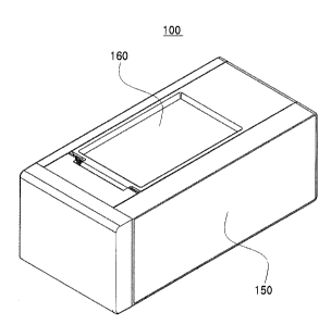
FIG. 1 is a schematic perspective view of a medicine dispensing device
according to an embodiment of the present invention;
FIG. 2 is a view of an internal configuration of a medicine dispensing device
according to an embodiment of the present invention;
FIGS. 3 through 5 are views of an internal configuration for explaining an
operating principle of a medicine dispensing device according to an embodiment
of the
present invention;
FIG. 6 is a schematic view of a medicine dispensing device according to
another
embodiment of the present invention;
FIG. 7 is a view of an internal configuration of a medicine dispensing device
according to another embodiment of the present invention;
FIGS. 8 through 11 are views for explaining an operating sequence of a
medicine dispensing device according to another embodiment of the present
invention;
FIG. 12 is a view of an operating principle of a medicine mounting portion and
a contact rotation portion of a medicine dispensing device according to
another
embodiment of the present invention;
FIGS. 13 through 15 are views of an operating principle of a dispensing
portion
and a discharge adjusting portion of a medicine dispensing device according to
another
embodiment of the present invention;
6
CA 02866906 2014-10-10
FIGS. 16 and 17 are views of an operating principle of a position movement
preventing portion of a medicine dispensing device according to another
embodiment of
the present invention;
FIG. 18 is a view of an alignment portion of a medicine dispensing device
according to another embodiment of the present invention;
FIG. 19 is a view for explaining a position movement principle of an alignment
portion of a medicine dispensing device according to another embodiment of the
present
invention;
FIG. 20 is a schematic perspective view of a guide portion of a medicine
dispensing device according to another embodiment of the present invention;
FIG. 21 is a schematic exploded perspective view of a guide portion of a
medicine dispensing device according to another embodiment of the present
invention;
and
FIGS. 22 and 23 are views for explaining the size of an entrance space using
the
guide portion of a medicine dispensing device according to another embodiment
of the
present invention.
DETAILED DESCRIPTION OF EXEMPLARY EMBODIMENTS
Hereinafter, exemplary embodiments of the present invention will be described
with reference to the drawings in detail. However, the present invention is
not limited
to the exemplary embodiments disclosed below, but one of ordinary skill in the
art that
understands the present invention can easily suggest another retrogressive
invention or
other embodiments within the scope of the present invention by adding,
modifying or
7
CA 02866906 2014-10-10
deleting other elements within the scope of the same idea. It will be
understood that
this is also included in the scope of the present invention.
Also, like reference numerals are used for like elements having the same
functions within the scope of the same idea shown in the drawings of each
embodiment.
FIG. 1 is a schematic perspective view of a medicine dispensing device
according to an embodiment of the present invention, and FIG. 2 is a view of
an internal
configuration of a medicine dispensing device according to an embodiment of
the
present invention.
Referring to FIGS. 1 and 2, a medicine dispensing device 100 according to an
embodiment of the present invention may include a medicine mounting portion
110 on
which medicines M are mounted and which transports the mounted medicines M, a
dispensing portion 120 that pivots between a receiving position at which the
medicines
M are received and a dispensing position at which the medicines M are
dispensed, and a
position movement preventing portion 130 that prevents the positions of the
medicines
M from moving.
Here, the medicines M may be in vials, as illustrated in FIG. 2. However,
embodiments of the present invention are not limited thereto. The medicines M
may
include medicines having various sizes and shapes, such as ampoules, refined
chemicals,
powders or pouch type chemicals, or medical instruments such as syringes.
A plurality of medicine dispensing devices 100 according to an embodiment of
the present invention may be mounted on a cartridge. As the cartridge is
mounted in
layers on which medicine dispensing equipment is mounted, the medicine
dispensing
8
CA 02866906 2014-10-10
device 100 may be mounted in a plurality of layers within the medicine
dispensing
equipment.
Thus, the medicine dispensing device 100 may store and dispense the medicines
M based on a medicine dispensing request, i.e., a prescription for a patient,
within the
medicine dispensing equipment. The operation of keeping and dispensing the
medicines M may be implemented by position movement of the medicine mounting
portion 110, the dispensing portion 120, and the position movement preventing
portion
130.
In detail, the medicine mounting portion 110 may be disposed in a body portion
150. The medicines M may be mounted upright on one surface of the medicine
mounting portion 110, and when the medicines M are required to be dispensed,
the
medicine mounting portion 110 may move the medicines M forward through
position
movement.
Here, in terms of terminology regarding directions, forward may refer to a
direction from the medicines M to the dispensing portion 120, and rearward may
refer to
the opposite direction.
The medicine mounting portion 110 may include a belt portion 114 on which the
medicines M are mounted and transported along an endless belt, and an escape
preventing portion 112 that is disposed on the belt portion 114 and prevents
the
medicines M from escaping from the belt portion 114.
The escape preventing portion 112 may be fastened to the belt portion 114 and
may interlock therewith. However, the escape preventing portion 112 may simply
be
mounted on one surface of the belt portion 114.
9
CA 02866906 2014-10-10
The escape preventing portion 112 may prevent the medicines M from falling
rearward due to inertia when the belt portion 114 moves and stops suddenly.
Thus, the
medicines M may be aligned to achieve accuracy in sequentially dispensing the
medicines M.
The body portion 150 may include a cover portion 160 for externally exposing
the medicine mounting portion 110 so that the medicines M can be replaced. The
cover
portion 160 may be mounted on a top surface of the body portion 150, as
illustrated in
FIG 1.
However, the cover portion 160 may be mounted at various positions including a
side of the body portion 150 according to an intention of one of ordinary
skill in the art.
The dispensing portion 120 may pivot between the receiving position at which
the medicines M transported by the medicine mounting portion 110 are received,
and the
dispensing position at which the received medicines M are dispensed.
Here, the receiving position may refer to a position before the dispensing
portion
120 is pivoted, i.e., a position of a state shown in FIG 2, and the dispensing
position
may refer to a position in a state in which pivoting of the dispensing portion
120 is
completed, as illustrated in FIG 5.
The dispensing portion 120 receives the medicines M transported by the
medicine mounting portion 110 at the receiving position and then is pivoted so
that
directions in which the medicines M are received and dispensed can be
different from
each other. In detail, the direction in which the medicines M are received may
refer to
a direction in which the medicines M are upright, and the direction in which
the
CA 02866906 2014-10-10
,
,
,
medicines M are dispensed may refer to a direction in which the medicines M
are laid
down.
In other words, the dispensing portion 120 may receive the medicines M
mounted on the medicine mounting portion 110 at the receiving position while
maintaining the same arrangement state. The dispensing portion 120 may include
an
inner surface that corresponds to at least a part of an outer surface of the
medicines M,
so as to receive one of the medicines M transported by the medicine mounting
portion
110 at the receiving position.
The dispensing portion 120 may include a surrounding portion 122 that
surrounds the part of the outer surface of the medicines M at the receiving
position and
exposes the other part thereof. The received medicines M may be dispensed as a
portion exposed by the surrounding portion 122 due to pivoting of the
dispensing portion
120.
In detail, the dispensing portion 120 may have a shape in which a part of a
side is
cut from a hollow cylinder, and the side that remains after being cut may be
the
surrounding portion 122.
The dispensing portion 120 may receive the medicines M transported by the
medicine mounting portion 110 at the receiving position and then may be
pivoted around
a portion on which the received medicines M are mounted, so that the received
medicines M can be automatically dispensed due to gravity.
In this case, a time at which the medicines M received by the dispensing
portion
120 are dispensed may be a time at which the dispensing portion 120 reaches
the
dispensing position, or before. This may vary according to a contact
relationship
11
CA 02866906 2014-10-10
(frictional coefficient) between the dispensing portion 120 and the medicines
M,
pivoting speed of the dispensing portion 120 and the size of the surrounding
portion 122.
The position movement preventing portion 130 may prevent position movement
of the medicines M to be received later on when the medicines M are received
by the
dispensing portion 120. Thus, the position movement preventing portion 130 may
cause the medicines M to be sequentially mounted on the dispensing portion 120
one at
a time.
In detail, the position movement preventing portion 130 may control flow of
the
medicines M into the dispensing portion 120 according to whether the
dispensing
portion 120 is pivoted. The position movement preventing portion 130 may
function as
a kind of shutter.
That is, the position movement preventing portion 130 may control whether the
medicines M pass through an outer side of the guide portion 140, which may be
implemented according to whether the dispensing portion 120 is pivoted.
Here, the guide portion 140 is a kind of guide member that may move the
medicines M mounted on the medicine mounting portion 110 to a position
corresponding to the receiving position. The guide portion 140 may include a
contact
rotation portion 142 that is in contact with the medicines M mounted on the
medicine
mounting portion 110 and rotates on the endless belt so as to move the
contacting
medicines M to the outer side of the guide portion 140.
The contact rotation portion 142 may be a kind of rubber ring having
elasticity.
The medicines M mounted on the medicine mounting portion 110 may pass through
the
12
CA 02866906 2014-10-10
=
outer side of the guide portion 140 and thus may be received by the dispensing
portion
120 placed at the receiving position.
As a result, a space through which only one of the medicines M may pass is
formed between one side end of the guide portion 140 and the body portion 150.
Opening and closing of the space may be controlled according to whether the
position
movement preventing portion 130 is pivoted.
A width that is viewed from an upper side of the guide portion 140 may narrow
toward a position corresponding to the receiving position, which may be
implemented
when one surface on which the contact rotation portion 142 and the medicines M
come
in contact as a slanted surface.
However, a part of the guide portion 140 that formed as a slanted surface is
not
limited to the one surface on which the contact rotation portion 142 and the
medicines M
come in contact, but may also be formed on the opposite surface.
Also, in order for the width of the guide portion 140 to narrow toward the
position corresponding to the receiving position, it is not necessary for at
least surface to
be slanted, and the surface may also be formed to be rounded.
The medicines M that come in contact with the contact rotation portion 142 may
be moved forward toward the outer side of the guide portion 140. As a result,
positions
of the medicines M that come in contact with the contact rotation portion 142
may be
different from each other.
Position movement of the medicine mounting portion 110, the position
movement preventing portion 130 and the dispensing portion 120 and rotation of
the
contact rotation portion 142 may be implemented by a motor that may be
disposed in the
13
CA 02866906 2014-10-10
body portion 150. However, embodiments of the present invention are not
limited
thereto, and the position movement and the rotation may be implemented by an
external
force supplied from the outside.
FIGS. 3 through 5 are views of an internal configuration for explaining an
operating principle of a medicine dispensing device according to an embodiment
of the
present invention.
First, referring to FIG. 3, the belt portion 114 of the medicine mounting
portion
110 is rotated so that the medicines M can be dispensed, and according to
rotation of the
contact rotation portion 142 of the guide portion 140, the medicines M mounted
on the
medicine mounting portion 110 flow into the outer side of the guide portion
140.
In this case, the position movement preventing portion 130 may be pivoted and
may cause one of the medicines M to pass through the outer side of the guide
portion
140. The medicine M that passes through the outer side of the guide portion
140 flows
into the dispensing portion 120 placed at the receiving position.
As illustrated in FIG. 4, when the medicine M is received by the dispensing
portion 120, the position movement preventing portion 130 may be returned to
its
original position and may prevent position movement of the medicines M to be
received
later on. Thus, the medicines M can be sequentially dispensed one at a time.
Referring to FIG. 5, the dispensing portion 120 that receives the medicines M
may be pivoted from the receiving position to the dispensing position. In this
procedure, the medicines M may automatically escape from the dispensing
portion 120
and may be dispensed outward due to gravity.
14
CA 02866906 2014-10-10
'
If dispensing of the medicines M is completed, the dispensing portion 120 may
be returned to the receiving position and may sequentially dispense the
medicines M one
at a time according to pivoting of the position movement preventing portion
130 and
passing of the medicines M through the outer side of the guide portion 140.
FIG. 6 is a schematic view of a medicine dispensing device according to
another
embodiment of the present invention, and FIG. 7 is a view of an internal
configuration of
a medicine dispensing device according to another embodiment of the present
invention.
Referring to FIGS. 6 and 7, a medicine dispensing device 200 according to
another embodiment of the present invention may include a medicine mounting
portion
210 that transports medicines M mounted in an upright state, a dispensing
portion 220
that moves between a receiving position at which the medicines M are received
and a
dispensing position at which the medicines M are dispensed, a position
movement
preventing portion 230 that prevents position movement of the medicines M, and
a guide
portion 240 that defines an entrance space S in which the medicines M mounted
on the
medicine mounting portion 210 enter the dispensing portion 220 at the
receiving
position.
Here, the medicines M may be in vials, as illustrated in FIG 7. However,
embodiments of the present invention are not limited thereto. The medicines M
may
include medicines having various sizes and shapes, such as ampoules, refined
chemicals,
powders or pouch type chemicals, or medical instruments such as syringes.
A plurality of medicine dispensing devices 200 according to an embodiment of
the present invention may be mounted on a cartridge. As the cartridge is
mounted in
layers on which medicine dispensing equipment is mounted, the medicine
dispensing
CA 02866906 2014-10-10
device 100 may be mounted in a plurality of layers within the medicine
dispensing
equipment.
Thus, the medicine dispensing device 200 may store and dispense the medicines
M based on a medicine dispensing request, i.e., a prescription for a patient,
within the
medicine dispensing equipment. The operation of storing and dispensing the
medicines
M may be implemented by position movement of the medicine mounting portion
210,
the dispensing portion 220, the position movement preventing portion 230, and
the guide
portion 240.
The medicine mounting portion 210 may be disposed in a body portion 250.
The medicines M may be mounted upright on one surface of the medicine mounting
portion 210, and when the medicines M are required to be dispensed, the
medicine
mounting portion 210 may be a kind of conveyor belt that may move the
medicines M
forward through position movement.
Here, in terms of terminology regarding directions, forward may refer to a
direction from the medicines M to the dispensing portion 220, and rearward may
refer to
the opposite direction.
The body portion 250 may include a cover portion 260 that externally exposes
the medicine mounting portion 210 so that the medicines M can be replaced. The
cover portion 260 may be mounted on a top surface of the body portion 250, as
illustrated in FIG 6. However, the cover portion 260 may be mounted at various
positions including a side of the body portion 250 according to an intention
of one of
ordinary skill in the art.
16
CA 02866906 2014-10-10
=
Here, the receiving position may refer to a position before the dispensing
portion
220 is moved, i.e., a position shown in FIG 7, and the dispensing position may
refer to a
position at which the medicines M are dispensed by the dispensing portion 220,
as
illustrated in FIG 11.
However, the dispensing position may also refer to a position of the medicines
M
after being dispensed by the dispensing portion 220, undergoing further
position
movement, and finally completed position movement.
The dispensing portion 220 receives the medicines M transported by the
medicine mounting portion 210 at the receiving position and then is
transported, i.e., is
rotated at a predetermined angle so that directions in which the medicines M
are
received and dispensed can be different from each other.
In detail, the dispensing portion 220 may receive the medicines M that enter
the
entrance space S defined by the guide portion 240 in the upright state at the
receiving
position and then may dispense the medicines M in a different direction from a
direction
in which the medicines M are received when the dispensing portion 220 reaches
the
dispensing position, or before.
In other words, the dispensing portion 220 may receive the medicines M in the
upright state and then may be moved to the dispensing position by rotation and
may
dispense the medicines M in the upright state to be in a laid state.
The dispensing portion 220 may include a support portion 222 on which the
medicines M moved from the medicine mounting portion 210 at the receiving
position
are mounted while being maintained in the upright state, and a preventing
portion 224
that is connected to the support portion 222 so as to prevent escape of the
medicines M
17
CA 02866906 2014-10-10
mounted on the support portion 222. The dispensing portion 220 may cause the
support portion 222 to be rotated around a rotation shaft 272 using a first
driving portion
(see 270 of FIGS. 13 through 15), and the medicines M mounted on the support
portion
222 may be automatically dispensed due to gravity.
Position movement of the dispensing portion 220 will be described with
reference to FIGS. 13 through 15 in detail.
The medicine dispensing device 200 according to an embodiment of the present
invention may further include a discharge adjusting portion 280 that adjusts
whether the
medicines M dispensed by the dispensing portion 220 are discharged to the
outside.
The discharge adjusting portion 280 may be mounted on the body portion 250 so
that the
discharge adjusting portion 280 can be transported.
The discharge adjusting portion 280 may be linked to the dispensing portion
220.
Thus, when the dispensing portion 220 is moved to the dispensing position, the
dispensing portion 220 is moved to be in an open state so that the medicines M
can be
discharged to the outside.
When the medicines M are received by the dispensing portion 220 of the
position
movement preventing portion 230, the discharge adjusting portion 280 may be an
element for preventing position movement of the medicines M to be received
later on.
Thus, the medicines M can be sequentially mounted on the dispensing portion
220 one at
a time.
When the medicines M mounted on the medicine mounting portion 210 pass
through the entrance space S, the position movement preventing portion 230 is
transported by a driving force of a second driving portion (see 290 of FIGS.
16 and 17)
18
CA 02866906 2014-10-10
=
,
so that communication between the entrance space S and the dispensing portion
220 can
be prevented. Thus, the medicines M to be received later on can be prevented
from
being received by the dispensing portion 220 at the receiving position.
When the medicines M that pass through the entrance space S are dispensed by
movement of the dispensing portion 220, the position movement preventing
portion 230
may be returned to its original position so that communication between the
entrance
space S and the dispensing portion 220 can be allowed. Thus, the medicines M
to be
dispensed later on can be received by the dispensing portion 220 at the
received position.
An operating principle of the position movement preventing portion 230 will be
described with reference to FIGS. 16 and 17 in detail.
The guide portion 240 may be an element that guides the medicines M mounted
on the medicine mounting portion 210 toward a position corresponding to the
receiving
position, defines the entrance space S in which the medicines M enter the
dispensing
portion 220 at the receiving position, and adjusts the size of the entrance
space S based
on the sizes of the medicines M.
In detail, the guide portion 240 may adjust the size of the entrance space S
in
which the medicines M enter the dispensing portion 220, to correspond to the
sizes of
the medicines M mounted on the medicine mounting portion 210. Thus, even when
the
sizes of the medicines M are changed, the guide portion 240 may adjust the
size of the
entrance space S to be suitable for the changed sizes of the medicines M.
The guide portion 240 may include a reference guide portion 242 that is fixed
to
a predetermined position of the body portion 250, a varying guide portion 244
mounted
on the reference guide portion 242 so as to be transported, and a contact
rotation portion
19
CA 02866906 2014-10-10
=
245 that rotates on the endless belt so as to guide the medicines M mounted on
the
medicine mounting portion 210 to correspond to the receiving position.
The size of the entrance space S may be changed according to a position at
which
the varying guide portion 244 is mounted on the reference guide portion 242.
Here, the
reference guide portion 242 and the varying guide portion 244 may include a
reference
axis X1 and a varying axis X2 for implementing rotation of the contact
rotation portion
245.
Here, a distance between the reference axis X1 and the varying axis X2 is
changed by the position at which the varying guide portion 244 is mounted on
the
reference guide portion 242. The distance may be in inverse proportion to the
size of
the entrance space S.
A detailed description thereof will be provided with reference to FIGS. 20
through 23.
The medicine dispensing device 200 according to an embodiment of the present
invention may further include an alignment portion 300 that defines the number
of
medicines M mounted on the medicine mounting portion 210 and is transported in
the
same direction in which the medicines M mounted on the medicine mounting
portion
210 are transported, so that the medicines M mounted on the medicine mounting
portion
210 can be maintained in the upright state when the medicines M mounted on the
medicine mounting portion 210 are transported.
The alignment portion 300 may be moved in a direction opposite to the
direction
in which the medicines M mounted on the medicine mounting portion 210 are
CA 02866906 2014-10-10
transported only using external force. This will be described with reference
to FIGS.
18 and 19 in detail.
FIGS. 8 through 11 are views for explaining an operating sequence of a
medicine dispensing device according to another embodiment of the present
invention.
First, referring to FIG. 8, when a plurality of medicines M are mounted
upright
on the medicine mounting portion 210, due to a driving force applied by an
external
force applying portion F, the medicine mounting portion 210 and the guide
portion 240
are linked to each other and transported.
In this case, the medicines M mounted on the medicine mounting portion 210
pass through the entrance space S provided between one side end of the guide
portion
240 and the body portion 250 one at a time due to rotation of the medicine
mounting
portion 210 and the contact rotation portion 245 of the guide portion 240. The
position
movement preventing portion 230 allows communication between the entrance
portion S
and the dispensing portion 220.
Here, the entrance portion S may be provided by the guide portion 240 so as to
correspond to the sizes of the medicines M. The medicine mounting portion 210
may
cause the medicines M that enter the entrance space S to be received by the
dispensing
portion 220 at the receiving position.
Referring to FIG. 9, when one medicine M passes through the entrance space S,
the medicine M may be received by the dispensing portion 220 placed at the
receiving
position. The position movement preventing portion 230 may be transported so
that
the medicine M to be dispensed later on cannot pass through the entrance space
S, and
21
CA 02866906 2014-10-10
=
,
thus communication between the entrance space S and the dispensing portion 220
is
prevented.
Referring to FIG. 10, when the medicines M moved from the medicine
mounting portion 210 in the upright state are mounted on the support portion
222 of the
dispensing portion 220 at the receiving position, the dispensing portion 220
is moved to
the dispensing position by the driving force of the first driving portion 270.
In this case, the discharge adjusting portion 280 is linked to the dispensing
portion 220 and is transported together with position movement of the
dispensing
portion 220.
Referring to FIG. 11, the dispensing portion 220 may receive the medicines M
in the upright state at the receiving position and then may dispense the
medicines M in a
different direction from a direction in which the medicines M are received
when the
dispensing portion 220 reaches the dispensing position, or before.
As described above, when one medicine M is discharged to the outside, the
procedure shown in FIGS. 8 through 11 may be repeated so that the medicines M
can be
sequentially discharged to the outside one at a time.
FIG. 12 is a view of an operating principle of a medicine mounting portion and
a contact rotation portion of a medicine dispensing device according to
another
embodiment of the present invention.
Referring to FIG. 12, the medicine mounting portion 210 and the contact
rotation portion 245 of the guide portion 240 may be transported so that the
medicines M
mounted on the medicine mounting portion 210 can be received by the dispensing
portion 220 at the receiving position.
22
CA 02866906 2014-10-10
Here, the driving force for position movement of the medicine mounting portion
210 and the contact rotation portion 245 may be provided by the external force
applying
portion F.
The external force applying portion F may include a gear that engages with a
first spur gear G1 . The gear may engage with the first spur gear G1 and then
rotate so
as to rotate the first spur gear Gl.
When the first spur gear G1 is rotated, as illustrated in FIG. 7, a second
spur
gear G2, a third spur gear G3, a fourth spur gear G4, a fifth spur gear G5, a
sixth spur
gear G6, and a seventh spur gear G7 are rotated, and due to rotation of the
fourth spur
gear G4, the medicine mounting portion 210 may be rotated on the endless belt.
When the sixth spur gear G6 is rotated, a pinion gear P having the same
rotation
shaft is also rotated due to rotation of the sixth spur gear G6, and a ring
gear R is rotated
about the reference axis X1 due to rotation of the pinion gear P.
The pinion gear P and the ring gear R may be bevel gears, and the contact
rotation portion 245 is rotated on the endless belt due to rotation of the
ring gear R about
the rotation shaft as the reference axis X1 and the varying axis X2.
Thus, position movement of the medicine mounting portion 210 and the contact
rotation portion 245 may be implemented by the same driving force provided by
the
external force applying portion F. Due to the position movement, the medicines
M pass
through the entrance space S and are received by the dispensing portion 220 at
the
receiving position.
23
CA 02866906 2014-10-10
=
However, the position movement of the medicine mounting portion 210 and the
contact rotation portion 245 is not necessarily implemented by the above-
mentioned
gears but may be implemented by different types of gears or a timing belt.
FIGS. 13 through 15 are views of an operating principle of a dispensing
portion
and a discharge adjusting portion of a medicine dispensing device according to
another
embodiment of the present invention.
Referring to FIGS. 13 through 15, when the medicines M in the upright state
are
received by the dispensing portion 220 at the receiving position, an eighth
spur gear G8
is rotated by the driving force provided by the first driving portion 270, and
a ninth spur
gear 09, a tenth spur gear G10, and an eleventh spur gear Gil are also rotated
due to
rotation of the eighth spur gear G8.
Here, when the ninth spur gear G9 is rotated, a dispensing protrusion P1
mounted on the ninth spur gear G9 is also rotated. The dispensing protrusion
P1 is in
contact with the support portion 222 of the dispensing portion 220 so that the
support
portion 222 can be rotated about the rotation shaft 272.
In detail, the support portion 222 may include a rounded surface 223 that
comes
in contact with the dispensing protrusion P 1 . The dispensing protrusion P1
is rotated
by rotation of the ninth spur gear G9 and is moved along the rounded surface
223, as
illustrated in FIGS. 14 and 15.
That is, the dispensing protrusion P1 is moved upward while being rotated.
Thus, the rounded surface 223 is pushed upward so that the support portion 222
can be
rotated about the rotation shaft 272.
24
CA 02866906 2014-10-10
=
When the eighth spur gear G8 is rotated by the driving force provided by the
first driving portion 270 and the eleventh spur gear Gil is rotated due to
rotation of the
eighth spur gear G8, a discharge protrusion P2 mounted on the eleventh spur
gear Gil is
also rotated.
When the discharge protrusion P2 is rotated, the discharge protrusion P2 is
moved along a through hole H1 of a connection portion 282 connected to the
discharge
adjusting portion 280. Due to the through hole H1 that is formed to be
rounded, the
connection portion 282 is moved in one direction and rotated.
Due to movement of the connection portion 282 in one direction and rotation of
the connection portion 282, the discharge adjusting portion 280 may be moved
upward
and may cause the medicines M to be discharged to the outside.
However, position movement of the dispensing portion 220 and the discharge
adjusting portion 280 is not necessarily implemented by the above-described
gears but
may be implemented by different types of gears or a timing belt.
FIGS. 16 and 17 are views of an operating principle of a position movement
preventing portion of a medicine dispensing device according to another
embodiment of
the present invention.
Referring to FIGS. 16 and 17, after the medicines M in the upright state are
received by the dispensing portion 220 at the receiving position, the position
movement
preventing portion 230 may be transported by a driving force of the second
driving
portion 290 and may prevent position movement of the medicines M to be
received later
on.
CA 02866906 2014-10-10
In detail, a first link portion 232 connected to the second driving portion
290 is
rotated by the driving force of the second driving portion 290. When the first
link
portion 232 is rotated, a second link portion 234 connected to the first link
portion 232 is
also rotated.
Here, when the second link portion 234 is rotated, the position movement
preventing portion 230 connected to the second link portion 234 may be moved
in a
straight direction and may prevent communication between the entrance space S
and the
dispensing portion 220.
When the medicines M that pass through the entrance space S are dispensed by
movement of the dispensing portion 220, the position movement preventing
portion 230
may be returned to the state shown in FIG 9 due to rotation of the first link
portion 232.
Thus, the position movement preventing portion 230 may allow communication
between
the entrance space S and the dispensing portion 220 so that the medicines M to
be
dispensed later on can be dispensed by the dispensing portion 220 at the
receiving
position.
FIG. 18 is a view of an alignment portion of a medicine dispensing device
according to another embodiment of the present invention, and FIG. 19 is a
view for
explaining a position movement principle of an alignment portion of a medicine
dispensing device according to another embodiment of the present invention.
Referring to FIGS. 18 and 19, an alignment portion 300 that is an element for
defining the number of medicines M mounted on the medicine mounting portion
210
may define a space A of the medicine mounting portion 210 in which the
medicines M
are mounted.
26
CA 02866906 2014-10-10
The alignment portion 300 may include a support portion 310 that supports the
medicines M and is in contact with the medicine mounting portion 210 so that
the
medicines M can be maintained in the upright state without being affected by
inertia
when the medicines M mounted on the medicine mounting portion 210 are
transported,
and a hangable portion 320 and a hangable-portion-moving portion 330 that are
mounted
on the support portion 310 so as to be transported such that the hangable
portion 320 and
the hangable-portion-moving portion 330 can be in contact with a hanging
portion 252
formed on an inner surface of the body portion 250 and can be moved together
with the
support portion 310.
The support portion 310 may be transported in the same direction in which the
medicines M mounted on the medicine mounting portion 210 are transported due
to
contact with the medicine mounting portion 210. However, the support portion
310
cannot be moved in a direction opposite to the direction in which the
medicines M are
transported without an external force.
In detail, the hanging portion 252 may be repeatedly framed as an inclined
surface. The hangable portion 320 may include an inclined end portion
corresponding
to the inclined surface.
Thus, the hangable portion 320 may be moved in the same direction in which
the medicines M mounted on the medicine mounting portion 210 are transported.
However, the hangable portion 320 is hung on a jaw of the hanging portion 252
and
cannot be moved in an opposite direction.
Here, after the medicines M mounted on the medicine mounting portion 210 are
dispensed by the dispensing portion 220, the alignment portion 300 is disposed
at a
27
CA 02866906 2014-10-10
position adjacent to the guide portion 240 and should be moved in the opposite
direction
for supply of new medicines M.
In this case, when an external force is applied to the hangable-portion-moving
portion 330, as illustrated in FIG 14, both ends of the hangable portion 320
may be
rotated so that contact with the hanging portion 252 can be released.
A space in which new medicines M are to be mounted can be secured again by
moving the hangable portion 320 in the opposite direction using the hangable-
portion-
moving portion 330 in a state in which the hangable portion 320 is spaced
apart from the
hanging portion 252. When the external force is removed, the hangable portion
320
comes in contact with the hanging portion 252 again due to elasticity.
FIG. 20 is a schematic perspective view of a guide portion of a medicine
dispensing device according to another embodiment of the present invention,
FIG. 21 is
a schematic exploded perspective view of a guide portion of a medicine
dispensing
device according to another embodiment of the present invention, and FIGS. 22
and 23
are views for explaining the size of an entrance space using the guide portion
of a
medicine dispensing device according to another embodiment of the present
invention.
Referring to FIGS. 20 through 23, the guide portion 240 may include a
reference
guide portion 242 fixed to the body portion 250, a varying guide portion 244
mounted
on the reference guide portion 242 so as to be transported, and a contact
rotation portion
245 that rotates on the endless belt so as to guide the medicines M mounted on
the
medicine mounting portion 210 toward a position corresponding to the receiving
position.
28
CA 02866906 2014-10-10
Here, the reference guide portion 242 and the varying guide portion 244 may
include a reference axis X1 and a varying axis X2 for implementing rotation of
the
contact rotation portion 245. The reference axis X1 and the varying axis X2
may be
linked to a reference roller R1 and a varying roller R2 and may be rotated.
The contact rotation portion 245 may contact the reference roller R1 and the
varying roller R2. When the first reference axis X1 and the reference roller
R1 are
rotated by rotation of a ring gear R, the first reference axis X1 and the
reference roller
R1 may be linked to each other and may be moved to the endless belt.
The contact rotation portion 245 may include a movement portion 246 that is a
kind of belt having elasticity and a plurality of pressurization portions 247
that are
spaced apart from the movement portion 246 and protrude from the contact
rotation
portion 245 so as to pressurize the medicines M that come in contact with the
movement
portion 246 toward the entrance space S.
One of the reference guide portion 242 and the varying guide portion 244 may
include an accommodation portion 248 that is depressed. The other may include
an
insertion portion 249 that is inserted into the accommodation portion 248 and
causes a
position of the varying guide portion 244 to be fixed to the reference guide
portion 242.
For example, as illustrated in FIG. 21, the accommodation portion 248 and the
insertion portion 249 may be formed at the reference guide portion 242 and the
varying
guide portion 244, respectively.
A plurality of accommodation portions 248 may be spaced apart from each
other, and a unit for adjusting the size of the entrance space S may be
determined based
on a separation distance.
29
CA 02866906 2014-10-10
That is, when the reference guide portion 242 and the varying guide portion
244
are separated from the guide portion 240 in the state shown in FIG 20, are
maintained in
the state shown in FIG 21 and then are moved in a direction of arrow B and
combined
with each other, the guide portion 240 in the state shown in FIG 23 may be
implemented.
The reference guide portion 242 and the varying guide portion 244 may be fixed
to the body portion 250 using a fixing portion 241.
In this case, the size of an entrance space S' may be greater than that of FIG
22.
Medicines M' having relatively larger sizes than those of FIG. 22 may also be
dispensed.
A distance between the reference axis X1 and the varying axis X2 decreases the
size of the entrance space S increases as the varying guide portion 244 moves
in the
direction of arrow B, and thus the distance and the size of the entrance space
S may be in
inverse proportion to each other.
In addition, the size of the entrance space S may be determined based on a
region
in which the reference guide portion 242 and the varying guide portion 244
overlap, and
the size of the entrance space S and the region may be in inverse proportion
to each other.
While the invention has been shown and described with reference to certain
exemplary embodiments thereof, it will be understood by those skilled in the
art that
various changes in form and details may be made therein without departing from
the
spirit and scope of the invention as defined by the appended claims.
30