Language selection

Search

Patent 2867009 Summary

Third-party information liability

Some of the information on this Web page has been provided by external sources. The Government of Canada is not responsible for the accuracy, reliability or currency of the information supplied by external sources. Users wishing to rely upon this information should consult directly with the source of the information. Content provided by external sources is not subject to official languages, privacy and accessibility requirements.

Claims and Abstract availability

Any discrepancies in the text and image of the Claims and Abstract are due to differing posting times. Text of the Claims and Abstract are posted:

  • At the time the application is open to public inspection;
  • At the time of issue of the patent (grant).
(12) Patent: (11) CA 2867009
(54) English Title: CONVERTIBLE TANDEM AXLE ARRANGEMENT AND METHOD FOR CONVERTING A TANDEM AXLE ARRANGEMENT TO EITHER OF A SINGLE DRIVE OR A DUAL DRIVE TANDEM AXLE ARRANGEMENT
(54) French Title: AGENCEMENT D'ESSIEU TANDEM TRANSFORMABLE ET PROCEDE POUR TRANSFORMER UN AGENCEMENT D'ESSIEU TANDEM EN ESSIEU TANDEM A ENTRAINEMENT SIMPLE OU A DOUBLE ENTRAINEMENT
Status: Granted
Bibliographic Data
(51) International Patent Classification (IPC):
  • B60K 17/36 (2006.01)
(72) Inventors :
  • ELLIOTT, MATTHEW (United States of America)
(73) Owners :
  • VOLVO TRUCK CORPORATION (Sweden)
(71) Applicants :
  • MACK TRUCKS, INC. (United States of America)
(74) Agent: NORTON ROSE FULBRIGHT CANADA LLP/S.E.N.C.R.L., S.R.L.
(74) Associate agent:
(45) Issued: 2019-10-08
(86) PCT Filing Date: 2012-07-19
(87) Open to Public Inspection: 2013-09-26
Examination requested: 2017-07-05
Availability of licence: N/A
(25) Language of filing: English

Patent Cooperation Treaty (PCT): Yes
(86) PCT Filing Number: PCT/US2012/047463
(87) International Publication Number: WO2013/141893
(85) National Entry: 2014-09-10

(30) Application Priority Data:
Application No. Country/Territory Date
61/613,083 United States of America 2012-03-20

Abstracts

English Abstract


A drive axle system can be converted between a single drive tandem axle
arrangement including a rear drive axle a
dual drive tandem axle arrangement. A forward bowl is provided for a forward
axie system. One of a geared forward carrier and an
ungeared forward carrier is mounted on the forward bowl, depending upon
whether a dual drive or a single drive tandem axle
arrangement is desi red. To convert to the other type of tandem axle
arrangement, the one of the geared forward carrier and the
ungeared forward carrier is removed from the fonvard bowl and replaced, with
the other one of the geared forward carrier and the
ungeared forward carrier.


French Abstract

L'invention porte sur un système d'essieu moteur qui peut être converti d'un agencement d'essieu tandem à entraînement simple, comprenant un essieu moteur arrière, en un agencement d'essieu tandem à double entraînement. Un cylindre avant est utilisé pour un système d'essieu avant. Un support avant à réducteur ou un support avant sans réducteur est monté sur le cylindre avant, en fonction de l'agencement d'essieu tandem voulu : à double entraînement ou à entraînement simple. Pour passer à l'autre type d'agencement d'essieu tandem, l'un des supports avant à réducteur et sans réducteur est retiré du cylindre avant et remplacé par l'autre des supports avant à réducteur et sans réducteur.

Claims

Note: Claims are shown in the official language in which they were submitted.


Claims:
1. A removable carrier housing for a forward tag axle system, comprising
means for
removably mounting the carrier housing to a top of a bowl of a forward tag
axle system; a
bearing arrangement; a shaft supported by the bearing arrangement and
extending from a
front end of the carrier housing to a rear end of the carrier housing, and a
body comprising one
or more attachment flanges for attaching the body to a vehicle.
2. The removable carrier housing as set for in claim 1, comprising a U-
joint hinge at
opposite ends of the shaft.
3. The removable carrier housing as set forth in claim 1, wherein the
mounting means
comprises a flange having a rim with a surface adapted to face a corresponding
surface on the
bowl.
4. A removable carrier housing for a forward tag axle system, comprising
means for
removably mounting the carrier housing to a bowl of a forward tag axle system;
a bearing
arrangement; and a shaft supported by the bearing arrangement and extending
from a front
end of the carrier housing to a rear end of the carrier housing, wherein the
mounting means
comprises a flange having a rim with a surface adapted to face a corresponding
surface on the
bowl, and wherein the rim surface is substantially planar and a longitudinal
axis of the shaft
extends generally parallel to a plane of the rim surface.
5. The removable carrier housing as set forth in claim 1, comprising a body
and a
passage through the body through which the shaft extends, the bearing
arrangement
comprising a bearing at a front end and bearing at a rear end of the housing.
6. The removable carrier housing as set forth in claim 4, comprising a body
comprising
one or more attachment flanges for attaching the body to a vehicle.
7. A single drive tandem axle arrangement comprising: a forward axle system
comprising
a forward bowl; and a forward carrier removably mounted on top of the forward
bowl and
comprising a shaft supported by bearings and extending from a forward end of
the forward
carrier to a rear end of the forward carrier, wherein the forward carrier
comprises a body
comprising one or more attachment flanges for attaching the body to a vehicle.
8

8. The single drive tandem axle arrangement as set forth in claim 7,
comprising a rear
drive axle system, the rear drive axle system comprising a geared rear
carrier, the single drive
tandem axle arrangement comprising an interaxle drive shaft extending between
the shaft and
the geared rear carrier.
9. The single drive tandem axle arrangement as set forth in claim 7,
comprising a U-joint
hinge at opposite ends of the shaft.
10. The single drive tandem axle arrangement as set forth in claim 7,
wherein the forward
carrier comprises a mounting flange having a rim with a surface adapted to
face and be
mounted to a corresponding surface on the forward bowl.
11. A single drive tandem axle arrangement comprising: a forward axle
system comprising
a forward bowl; and forward carrier removably mounted on the forward bowl and
comprising a
shaft supported by bearings and extending from a forward end of the forward
carrier to a rear
end of the forward carrier, wherein the forward carrier comprises a mounting
flange having a
rim with a surface adapted to face and be mounted to a corresponding surface
on the forward
bowl, and wherein the rim surface is substantially planar and a longitudinal
axis of the shaft
extends generally parallel to a plane of the rim surface.
12. The single drive tandem axle arrangement as set forth in claim 7,
wherein the forward
carrier comprises a body and a passage through the body through which the
shaft extends,
the bearings comprising a bearing at a front end and bearing at a rear end of
the passage.
13. The single drive tandem axle arrangement as set forth in claim 11,
wherein the forward
carrier comprises a body comprising one or more attachment flanges for
attaching the body to
a vehicle.
14. A method of converting a drive axle system between a single drive
tandem axle
arrangement comprising a rear drive axle a dual drive tandem axle arrangement,
comprising:
providing a forward bowl for a forward axle system mounting one of a geared
forward
carrier and an ungeared forward carrier on the forward bowl;
removing the one of the geared forward carrier and the ungeared forward
carrier from
the forward bowl and replacing it with the other one of the geared forward
carrier and the
ungeared forward carrier,
9

mounting the one of the geared forward carrier and the ungeared forward
carrier to the
forward bowl by attaching a mounting flange of the one of the geared forward
carrier and the
ungeared forward carrier to the forward bowl, wherein the mounting flange has
a rim with a
surface adapted to face and be mounted to a corresponding surface on the
forward bowl,
wherein the forward axle system comprises two generally coaxial arms extending
in opposite
directions from the forward bowl, the one of the geared forward carrier and
the ungeared
forward carrier comprises front and rear U-joint hinges, axes of the arms and
a line between
the front and rear U-joint hinges defining a plane, the surface of the rim of
the mounting flange
being substantially planar and parallel to the plane, and
removing the one of the geared forward carrier and the ungeared forward
carrier from
the forward bowl by lifting the one of the geared forward carrier and the
ungeared forward
carrier perpendicular to the plane.
15. The method as set forth in claim 14, comprising providing a rear drive
axle system, and
linking the one of the geared forward carrier and the ungeared forward carrier
to the rear drive
axle system by an interaxle drive shaft.
16. The method as set forth in claim 14, wherein the forward axle system
comprises two
generally coaxial arms extending in opposite directions from the forward bowl,
the method
comprising installing axle shafts in the arms when mounting the geared forward
carrier on the
forward bowl.
17. The method as set forth in claim 14, wherein the forward axle system
comprises two
generally coaxial arms extending in opposite directions from the forward bowl,
the method
comprising removing axle shafts from the arms when mounting the ungeared
forward carrier
on the forward bowl.
18. A method of converting a drive axle system between a single drive
tandem axle
arrangement comprising a rear drive axle a dual drive tandem axle arrangement,
comprising:
providing a forward bowl for a forward axle system;
mounting one of a geared forward carrier and an ungeared forward carrier on
the
forward bowl; and
removing the one of the geared forward carrier and the ungeared forward
carrier from

the forward bowl and replacing it with the other one of the geared forward
carrier and the
ungeared forward carrier.
19. The method as set forth in claim 18, comprising providing a rear drive
axle system, and
linking the one of the geared forward carrier and the ungeared forward carrier
to the rear drive
axle system by an interaxle drive shaft.
20. The method as set forth in claim 18, comprising mounting the one of the
geared
forward carrier and the ungeared forward carrier to the forward bowl by
attaching a mounting
flange of the one of the geared forward carrier and the ungeared forward
carrier to the forward
bowl.
21. The method as set forth in claim 20, wherein the mounting flange has a
rim with a
surface adapted to face and be mounted to a corresponding surface on the
forward bowl.
22. The method as set forth in claim 21, wherein the forward axle system
comprises two
generally coaxial arms extending in opposite directions from the forward bowl,
the one of the
geared forward carrier and the ungeared forward carrier comprises front and
rear U -joint
hinges, axes of the arms and a line between the front and rear U-joint hinges
defining a plane,
the surface of the rim of the mounting flange being substantially planar and
parallel to the
plane, and the method comprising removing the one of the geared forward
carrier and the
ungeared forward carrier from the forward bowl by lifting the one of the
geared forward carrier
and the ungeared forward carrier perpendicular to the plane.
23. The method as set forth in claim 21, wherein the forward axle system
comprises two
generally coaxial arms extending in opposite directions from the forward bowl,
the method
comprising installing axle shafts in the arms when mounting the geared forward
carrier on the
forward bowl.
24. The method as set forth in claim 21, wherein the forward axle system
comprises two
generally coaxial arms extending in opposite directions from the forward bowl,
the method
comprising removing axle shafts from the arms when mounting the ungeared
forward carrier
on the forward bowl.
11

Description

Note: Descriptions are shown in the official language in which they were submitted.


CA 02867009 2014-09-10
WO 2013/141893 PCT/US2012/047463
CONVERTIBLE TANDEM .AXLE ARRANGEMENT AND METHOD FOR CONVERTING
A TANDEM AXLE. ARRANGEMENT TO EITHER OF A SINGLE :DRIVE OR A :DUAL
DRIVE.TANDEM AXLE. ARRANGEMENT
BACKGROUND AND SUMMARY
[0001] The present invention relates to a convertible tandem axle arrangement
and method
wherein a single drive tandem axle arrangement can be converted to a dual
drive tandem axle
arrangement, or vice .versa.
[0002] Tandem axle arrangements for truck. tractors are typically provided
with either a. single
drive axle and a single tag axle (referred to as a 6x2 arrangement) or with
dual drive axles
(referred to. as a 6x4. arrangement). Single drive tandem axle arrangements
tend to have lighter
weight, provide for better fuel economy, lower installation cost, and offer
improved reliability
over dual drive tandem axle arrangements_ They are mostly used in highway
applications.
[0003] Dual drive tandem axle arrangements tend to be more versatile than
single drive tandem
axle arrangements and, consequently, single. drive tandem axle arrangements
tend to have low
resale value because it is difficult and. expensive to convert, them to dual
drive tandem axle
arrangements.
[0004] Most tag axles have a different profile and use different suspension
and wheel equipment
than the drive axle of the tandem axle arranuement, In a. conversion of a
single drive tandem
axle arrangement to a dual drive tandem axle arrangement, not only must the
entire original tag
axle be replaced with the new drive. axle, ordinarily much or all of .the
suspension and wheel
equipment must be replaced with new equipment. it Islesirable to provide a
tandem axle
arrangement that can be conveniently convened from a single drive tandem axle
arrangement to

CA 02867009 2014-09-10
WO 2013/141893 PCT/US2012/047463
a dual drive tandem axle arrangement. it is particularly desirable to provide
a tandem axle
arrangement that permits the conversion without the need. to replace the
entire axle arrangement,
suspension equipment, and wheel equipment.
[0005] In thesingle drive axle arrangemergs, the driveaxle can be provided on
aforward axle or
a rear axle. However, at take off of a tandem vehicle, weight shifts
rearwardly, putting load on
the rear axle and taking load off of the front axle. Accordingly, it can be
advantageous to
provide the drive We on the rear axle because that arrangement provides
improved traction at
take off It is desirable to provide a convertible tandem axle arrangement that
has a rear drive
axle when used as a single drive tandem axle arrangement,
[0006] According to an aspect of the present invention, a removable carrier
housing for a
forward tag axle system comprises means for removably mounting the carrier
housing: to a bowl
of a forward tag axle system, a bearing arrangement, and a shaft supported by
the bearing
arrangement and extending from a .front end of the carrier housing to a .rear
end of the carrier
housing.
[0.007] According to another aspect of the present invention,a single drive
tandem axle
arrangement comprises a fbrward axle system comprising a forward bowl, and a
forward carrier
removably mounted on the .forward bowl and comprising a shaft supported by
bearings and
extending from a forward end of the forward carrier to a rear end of the
forward carrier.
[0008] According to another aspect. of the present invention, a method of
converting a drive axle
system between. a single drive tandeni axle arrangement comprising a rear
drive axle a dual drive
tandem axle arrangement comprises providing a forward bowl for a forward axle
system.,
mounting one of a geared-forward carrier and an =ungeared forward carrier on
the forward bowl,.
and removing the one of the geared forward carrier and the ungeared forward
carrier from the.
2

CA 02867009 2014-09-10
WO 2013/141893 PCT/US2012/047463
forward bowl and replacing it with the other one of the geared forward carrier
and the ungeared
forward carrier.
BRIEF DESCRIPTION OF THE DRAWINGS
[0009] The features and advantages of the present invention are well
understood by reading the
following detailed description in conjunction with the drawings in which like
numerals indicate,
similar elements and in Which:
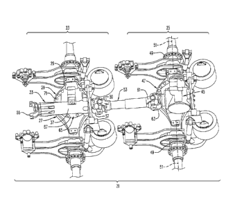
[0010] FIG. 1 is a perspective.view of a single drive tandem axle
arrange.mentaccording to an
aspect of the present invention;
[0011] FIG. 2 is a perspective view of a dual drive tandem axle arrangement
according to an
aspect of the present invention;
[0012] FIG. 3 is a cross-sectional view of a conventional dual drive tandem
axle arrangement
according to an aspect a the present invention;
[0013] Fla 4 is an upper left side, perspective, eross-seetional view of a
carrier housing fora.
tagiaile of a. single drive tandem axle arrangement according to an aspect. Of
the present
invention;
[0014] .FIGS. 5A-5C are upper left side, upper right, side, and lower left
side perspective .views
of a carrier housing for a tag axle of a single drive tandem axle arrangement
according to an
aspect of the present invention.
DETAILED DESCRIPTION.
[0015] A convertible tandem axle. arrangement according to an aspect of the
present invention is
convertible from a single drive tandem axle arrangement 21 comprising a.
forward tag. axle.
3

CA 02867009 2014-09-10
WO 2013/141893 PCT/US2012/047463
system .23 and a rear drive:axie system 25 as seen in FIG. 1 to a dual drive
tandem axle
arrangement 21. ' comptisinga forward drive axle system 23' and the rear drive
axle system 25 as
seen in FIG: 2:
[0016] The dual drive tandem axle arrangeMent ' can be a conventional. 6x4
tandem axle
arrangement such as the arrangement available from .Mack Trucks, Inc.,
Greensboro, NC, 'US.,
including the Mack Trucks C1.50 Series axle carriers 121 as seen in FIG, 3
where a forward drive
axle system 123 includes a power divider lock out 127 and forward and rear
drive axle systems
(1.23 and 125) are linked by an inter-axle drive shaft. 129, The C150 Series
axle Carrier 1.21 also
includes gears 131 in the forward and rear drive axle systems that are adapted-
to be connected to
axle shafts (00t Shown in FIG. 3) disposed in arms (not shown in HG. 3) to
drive the axle shafts
and wheels (not Shown) attached to the axle shafts.
[0017] The single drive tandem axle arrangement (6x2) 21 shown in FIG.. 1
includes a forward
tag axle system 23 comprising a forward bowl .27. Two generally coaxial arms
29 ordinarily
extend in opposite directions from the forward. bowl 27 and, when the forward
bowl is converted
to use in a forward. drive axle system 2:3%. axle shafts 31 (shown in phantom
in FIG, 2) are
removably mounted in the arms.
[001.8] The single drive tandem axle arrangement 21 Shown in FIG .1 includes a
forward carrier
33 removably mounted on the forward bowl 27. As seen in FIG. 4, the forward
carrier 33
includes a shaft 35 supported by bearings and extending from a. forward end of
the forward
carrier to a rear end of the forward carrier. The forward. carrier 33
comprises a body 37 and a
.passage:39 through the body through which the shalt 35 extends. The bearings
comprise a
bearing 41 at a front end and bearing 43 at a rear end of the passage 39 in
the body 37 of the
4

CA 02867009 2014-09-10
WO 2013/141893 PCT/US2012/047463
carrier 33. Gears of the type shown in the forward drive axle system 123 in
FIG. 3 are ordinarily
omitted from the forward carrier 33 and forward bowl 29.
[009] The single drive tandem axle arrangement 21 also includes the rear drive
axle system 25.
The rear drive axle system 25 comprises a geared rear carrier 45 and tear bowl
47 on which the
rear carrier is mounted. Two generally coaxial arms 49 ordinarily extend in
opposite directions
from the rear bowl 47 and axle shafts 51 (shown in phantom in FIGS, i and 2)
are mounted in
the arms, An interaxle drive shaft 53 extends between the shaft 35 and the
geared rear carrier 45.
U-joint hinges -55 and 57 are. ordinarily provided at opposite ends of the
shaft 35. The forward 1..1-
joint hinge 55 is ordinarily connected to the 1J-joint hinge (not shown) of a
drive shaft (not
shown), the rear U-joint hinge 57 is ordinarily connected to a forward LI-
joint hin0 59 on the
interaxle drive shaft 53, and a rear U-joint hinge 61 on the interaxle drive
shaft is ordinarily
connected to a Ujoint hinge 63 on a shaft extending into the geared rear
carrier 45.
[0020] To facilitate conversion of the single drive tandem axle arrangement 21
to the dual drive
tandem axle arrangement 21', as seen, for example, in FIGS, 5A-5C, the forward
carrier 33
ordinarily comprises a mounting flange 65 having a rim 67 with a surface 69
(FIG. 5C) adapted
w face and be mounted to a corresponding surface, usually a flange rim, on the
forward bowl 27.
Typically, the forward carrier 33 is mounted to the forward bowl 27 by means
of bolts 71 (FIGS.
1 and 2) extending through holes in flange rims on the forward carrier and the
forward bowl,
Holes 73 are seen on the flange rim 67 of forward carrier 33 in FIG. 4. In a
similar fashion, the
geared rear carrier 45 is typically mounted on the rear bowl 47 by bolts 71
attaching flanged
surfaces of the geared rear carrier and the rear bowl.
[0021] Ordinarily, the rim surface 69 is substantially planar and a
longitudinal axis of the shaft:
35 extends generally parallel to a plane of the rim surface, The fOrward axle
system 23 or 23'

CA 02867009 2014-09-10
WO 2013/141893 PCT/US2012/047463
comprises the two generally coaxial arms 29 extending in opposite directions
from the forward
bowl 27, and the one of the geared forward carrier 3.3 and the ungeared
forward carrier 33
comprises the front and rear LI-joint hinges 55 and 57, with axes of the arms
and a line between
the fropt and rear Ujoint hinges ordinarily at least approximately defining
the plane of the
surface 69of the rim 67 of the mounting flange. With this configuration, when
the bolts 71 are
removed from the forward carrier 33 and the forward bowl. 27, the forward
carrier can ordinarily
conveniently be lifted vertically off of the forward bowl when it is desired
to remove the forward
carrier. Similarly,..when it is desired to mount a geared forward. carrier
3rto the forward bowl
27, the geared forward carrier can be 'lowered vertically onto the forward
bowl.
[0022] One or mote attachment flanges 75 for attaching, the body 33 to a
vehicle (not shown) Yia
bolts (not shown). is ordinarily also provided.
[0023] The convertible tandem axle arrangement can be arranged the forward
carrier 33 can be
removed and replaced with a geared forward carrier 33' and axle shafts 31.
using the same
interaxie drive shaft and suspension. Thus, minimal additional parts are
required. In addition,
when the tandem axle arrangement is used in a 6x2 (single drive tandem axle)
arrangement, the
drive axle is the rear axle, which optimizesi traction at take-off
[0024] In a method of converting a drive axle system between a single drive
tandem axle
arrangement 21 (FIG. 1.) comprising a -rear drive axle 25 and a dual drive
tandem axle,
arrangement 21' (FIG, 2), a forward bowl 27 is provided for a forward axle
system. One of a
geared forward carder 33' and an ung,eared forward carrier 23 is mounted on
the forward bowl.
27 .to form a forward drive axle system 23' and a forward tag Axle system 23,
respectively. To
convert the forward drive axle system .23' and a forward tag Akie. system 23
to the othetgystem,
Le., to a farward.tag axle system 23 and a forward drive axle sygem 23',
respectively, the one of
6

CA 02867009 2014-09-10
WO 2013/141893 PCT/US2012/047463
the geared forward carrier and the tmgeared forward carrier is removed from
the forward bowl
27 and replaced with the other one of the geared forward carrier and the
ungeared forward
carrier. This is ordinarily accomplished by removing bolts 7.1 securing the
forward. carrier 23 or
21' to the forward bowl 27, disconnecting the 'Ll-joint hinges connecting the
forward carrier to
the drive shaft and the interaxle drive Shaft 53, removing bolts attaching the
attachment flange 75
of the forward carrier to the vehicle, vertically lifting the forward carrier
out ofoff of the forward
housing, installing or removing axle shafts, depending upon whether the axle
system will be a.
drive axle of a tag axle, respectively, and vertically lowering the new
replacement forward
carrier onto the forward housing and attaching it to the drive Shafts and the
vehicle.,
[0025] In the present application, the use of terms such as "including" is
open-ended and is
intended to have the same meaning as terms such as 'comprising" and not
preclude the presence
of other structure, material, or acts. Similarly, .though the use of terms
such as "can" or "may" is
intended to be open-ended and to reflect that structure, material, or acts are
not necessary, the
failure to use such terms is not intended to reflect that structure, material,
or acts are essential.
To the extent that structure, material, or acts are presently considered to be
essential, they are
identified as such,
[002.611 While this invention has been illustrated and described in accordance
'with a prekrred
embodiment, it is recognized that variations and changes may be made therein
without departing
from the invention as set forth in the claims.
7

Representative Drawing
A single figure which represents the drawing illustrating the invention.
Administrative Status

For a clearer understanding of the status of the application/patent presented on this page, the site Disclaimer , as well as the definitions for Patent , Administrative Status , Maintenance Fee  and Payment History  should be consulted.

Administrative Status

Title Date
Forecasted Issue Date 2019-10-08
(86) PCT Filing Date 2012-07-19
(87) PCT Publication Date 2013-09-26
(85) National Entry 2014-09-10
Examination Requested 2017-07-05
(45) Issued 2019-10-08

Abandonment History

There is no abandonment history.

Maintenance Fee

Last Payment of $263.14 was received on 2023-07-05


 Upcoming maintenance fee amounts

Description Date Amount
Next Payment if small entity fee 2024-07-19 $125.00
Next Payment if standard fee 2024-07-19 $347.00

Note : If the full payment has not been received on or before the date indicated, a further fee may be required which may be one of the following

  • the reinstatement fee;
  • the late payment fee; or
  • additional fee to reverse deemed expiry.

Patent fees are adjusted on the 1st of January every year. The amounts above are the current amounts if received by December 31 of the current year.
Please refer to the CIPO Patent Fees web page to see all current fee amounts.

Payment History

Fee Type Anniversary Year Due Date Amount Paid Paid Date
Registration of a document - section 124 $100.00 2014-09-10
Application Fee $400.00 2014-09-10
Maintenance Fee - Application - New Act 2 2014-07-21 $100.00 2014-09-10
Maintenance Fee - Application - New Act 3 2015-07-20 $100.00 2015-06-11
Maintenance Fee - Application - New Act 4 2016-07-19 $100.00 2016-06-08
Maintenance Fee - Application - New Act 5 2017-07-19 $200.00 2017-06-13
Request for Examination $800.00 2017-07-05
Maintenance Fee - Application - New Act 6 2018-07-19 $200.00 2018-07-05
Maintenance Fee - Application - New Act 7 2019-07-19 $200.00 2019-06-17
Final Fee $300.00 2019-08-12
Maintenance Fee - Patent - New Act 8 2020-07-20 $200.00 2020-07-06
Maintenance Fee - Patent - New Act 9 2021-07-19 $204.00 2021-07-05
Registration of a document - section 124 2022-06-14 $100.00 2022-06-14
Maintenance Fee - Patent - New Act 10 2022-07-19 $254.49 2022-07-07
Maintenance Fee - Patent - New Act 11 2023-07-19 $263.14 2023-07-05
Owners on Record

Note: Records showing the ownership history in alphabetical order.

Current Owners on Record
VOLVO TRUCK CORPORATION
Past Owners on Record
MACK TRUCKS, INC.
Past Owners that do not appear in the "Owners on Record" listing will appear in other documentation within the application.
Documents

To view selected files, please enter reCAPTCHA code :


To view images, click a link in the Document Description column. To download the documents, select one or more checkboxes in the first column and then click the "Download Selected in PDF format (Zip Archive)" or the "Download Selected as Single PDF" button.

List of published and non-published patent-specific documents on the CPD .

If you have any difficulty accessing content, you can call the Client Service Centre at 1-866-997-1936 or send them an e-mail at CIPO Client Service Centre.


Document
Description 
Date
(yyyy-mm-dd) 
Number of pages   Size of Image (KB) 
Abstract 2014-09-10 1 73
Claims 2014-09-10 4 226
Drawings 2014-09-10 4 151
Description 2014-09-10 7 528
Representative Drawing 2014-09-10 1 40
Cover Page 2014-11-28 2 62
Request for Examination 2017-07-05 2 74
Examiner Requisition 2018-05-22 3 162
Amendment 2018-11-22 6 251
Claims 2018-11-22 4 184
Final Fee 2019-08-12 2 68
Representative Drawing 2019-09-11 1 19
Cover Page 2019-09-11 1 53
PCT 2014-09-10 1 48
Assignment 2014-09-10 8 360