Note: Descriptions are shown in the official language in which they were submitted.
CA 02867699 2014-09-17
WO 2013/142345
PCT/US2013/032207
1
VOLUME METERING DISPENSER
CROSS-REFERENCE TO RELATED APPLICATIONS
This Application claims priority to US Provisional Application No.
61/612661, filed March 19, 2012, the entire contents of which are herein
incorporated
by reference.
STATEMENT REGARDING FEDERALLY SPONSORED RESEARCH
Not Applicable.
BACKGROUND OF THE INVENTION
Various types of fluid dispensers are known in the art. Dispensers used
for dispensing detergent or other liquids, for example, can include a flexible
push-
button. The flexible push-button can, in some example, be used in conjunction
with a
valve to open and close the valve, thereby dispensing the detergent or other
liquid.
In using such dispensers, it can be difficult for the operator to know how
much detergent or other fluid has been dispensed, at least without having a
separate
measuring apparatus. Consequently, there remains a need for a fluid dispenser
that
informs the operator how much fluid is being dispensed.
The art referred to and/or described above is not intended to constitute an
admission that any patent, publication or other information referred to herein
is "prior
art" with respect to this invention. In addition, this section should not be
construed to
mean that a search has been made or that no other pertinent information as
defined in 37
C.F.R. 1.56(a) exists.
All US patents and applications and all other published documents
mentioned anywhere in this application are incorporated herein by reference in
their
entirety.
Without limiting the scope of the invention a brief summary of some of
the claimed embodiments of the invention is set forth below. Additional
details of the
summarized embodiments of the invention and/or additional embodiments of the
invention may be found in the Detailed Description of the Invention below.
CA 02867699 2014-09-17
WO 2013/142345
PCT/US2013/032207
2
BRIEF SUMMARY OF THE INVENTION
In some embodiments, a fluid dispensing assembly comprises a body
having therein a fluid cavity. In some embodiments, the body comprises a body
wall.
The body wall has at least a portion thereof that is transparent or
translucent. The
transparent or translucent portion permits an operator to see the level of
fluid within at
least a portion of the fluid cavity. The fluid dispensing assembly further
comprises a
valve disposed within the body portion. The valve comprises a seal and the
seal is
selectively engaged to the body. The fluid dispensing assembly further
comprises a
resilient member being elastically deformable. In some embodiments, the valve
is
attached to the resilient member.
In some embodiments, the valve further comprises a stem. At least a
portion of the stem is engaged to the resilient member.
In some embodiments, the stem has a first opening therein.
In some embodients, the stem has a second opening therein. The second
opening is longitudinally offset from the first opening along the length of
the stem.
In some embodients, the stem comprises at least one guide member.
In some embodiments, the body comprises at least one guide channel.
The at least one guide member is slidable within the at least one guide
channel.
In some embodiments, the stem comprises a first recessed portion and a
second recessed portion. In some embodiments, the second recessed portion is
longitudinally offset from the first recessed portion along the length of the
stem.
In some embodiments, the resilient member comprises a dome-shaped
push button.
In some embodiments, the dome-shaped push button has an interior and
an exterior. In some embodiments, the interior has a protruding member
extending
therefrom.
In some embodiments, the fluid dispensing assembly has closed
configuration and a flow configuration.
CA 02867699 2014-09-17
WO 2013/142345
PCT/US2013/032207
3
In some embodiments, the fluid cavity defines a first chamber and a
second chamber. In some embodiments, the first and second chambers are in
fluid
communication when the fluid dispensing assembly is in the closed
configuration.
In some embodiments, the second chamber is isolated form the first
chamber when the fluid dispensing assembly is in the flow configuration.
In some embodiments, the second chamber is vented when the fluid
dispensing assembly is in the flow configuration.
In some embodiments, the body further defines a third chamber. In some
embodiments, the second chamber vents through the third chamber when the fluid
dispensing assembly is in the flow configuration.
In some embodiments, the second chamber is isolated from the third
chamber when the fluid dispensing assembly is in the closed configuration.
In some embodiments, the invention is directed to a fluid dispensing
assembly having a flow configuration and a closed configuration. The fluid
dispensing
assembly comprises a body having a fluid cavity. The body has a first chamber,
a
second chamber, and a body wall. The body wall extends along at least a
portion of the
second chamber and has at least a portion that is transparent or translucent
such that the
level of fluid within the second chamber is visible from outside of the second
chamber.
In some embodiments, the fluid dispensing assembly further comprises a valve
disposed
within the body. In some embodiments, the valve isolates the first chamber
from the
second chamber when the assembly is in the flow configuration. In some
embodiments,
the valve comprises a seal and a stem, the seal is selectively engaged to the
body. In
some embodiments, the assembly further comprises a resilient member. In some
embodiments, the resilient member is elastically deformable. In some
embodiments, the
valve is attached to a portion of the stem.
In some embodiments, in the closed configuration, the first and second
chambers are in fluid communication with one another.
In some embodiments, the valve has a first opening extending
therethrough. In some embodiments, in the closed configuration, the first
opening
allows for fluid communication between the first and second chambers.
CA 02867699 2014-09-17
WO 2013/142345
PCT/US2013/032207
4
In some embodiments, the body has a third chamber. Further, in some
embodiments, the second chamber is vented through the third chamber when the
fluid
dispensing assembly is in the flow configuration.
In some embodiments, the second chamber is vented through the first
chamber when the assembly is in the closed configuration.
BRIEF DESCRIPTION OF THE SEVERAL VIEWS OF THE DRAWING(S)
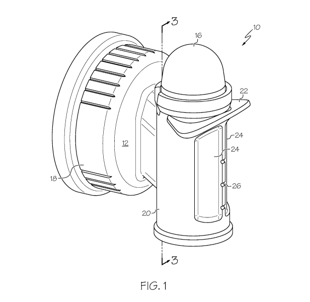
FIG. 1 shows a perspective view of an embodiment of a fluid dispensing
assembly.
FIG. 2 shows a side view of the fluid dispensing assembly of FIG. 1.
FIG. 3 shows a cutaway view of the fluid dispensing assembly of FIG. 1.
FIG. 4 shows a cutaway view of the fluid dispensing assembly of FIG. 2.
FIG. 5 shows a perspective view of an embodiment of a valve of the fluid
dispensing assembly of FIG. 1.
FIG. 6 shows another perspective view of the valve of FIG. 5.
FIG. 7 shows a cutaway view of the valve of FIG. 5.
FIG. 8 shows a perspective view of an embodiment of a resilient member
of the fluid dispensing assembly of FIG. 1.
FIG. 9 shows a cross-sectional view of the resilient member of FIG. 8.
FIGs. 10A, 10B, and 10D-10F show the fluid dispensing assembly of
FIG. 1 having various levels of fluid therein and being dispensed therefrom.
FIG. 10C shows a cutaway detailed view of the fluid dispensing
assembly of FIG. 10B.
DETAILED DESCRIPTION OF THE INVENTION
While this invention may be embodied in many different forms, there are
described in detail herein one or more specific embodiments. This description
is an
exemplification of the principles of the invention and is not intended to
limit it to the
particular embodiments illustrated.
For the purposes of this disclosure, like reference numerals in the figures
shall refer to like features unless otherwise indicated.
CA 02867699 2014-09-17
WO 2013/142345
PCT/US2013/032207
As shown for example in FIGs. 1 and 2, in some embodiments, a fluid
dispensing assembly comprises a body 12, a valve 14 (FIG. 3) and a resilient
member
16. The body 12 further comprises a container engaging portion 18 and a
dispensing
portion 20. The fluid dispensing portion 20 comprises finger holds 22.
5 In some embodiments, the body 12 has one or more portions
thereof that
are see-through so the operator can view the volume of fluid within the body.
In some
embodiments, the body 12 can be made from a transparent or translucent
material,
thereby permitting the operator to see through the body 12. In some
embodiments, the
body 12 is formed from a generally opaque material but certain portions of the
body 12
are sufficiently thin to permit the passage of light therethrough. As shown
for example
in FIG. 1, the body 12 comprises viewing portions 24, wherein the material
forming the
body 12 is thin enough for the operator to view whether fluid is present, and
to what
degree, within the dispensing portion 20. It will be appreciated that the body
12 can
comprise any suitable number of viewing portions 24, for example, between one
and
ten.
In some embodiments, the body 12 further comprises at least one
indicator mark 26. Indicator marks 26 show the level of fluid within at least
a portion of
the dispensing portion 20. Again, it will be appreciated that the dispensing
portion 20
can have any suitable number of indicator marks 26, for example between one
and ten.
Turning to FIG. 3, a cross-sectional view of the fluid dispensing
assembly 10 is shown without the resilient member 16. As shown in FIG. 3, in
some
embodiments, the body 12 comprises a body wall 13 and a fluid cavity 28 within
the
body 12. Further, in some embodiments, the fluid cavity 28 defines a first
chamber 30
and a second chamber 32. In some embodiments, the body 12 comprises a throat
25
connecting the container engaging portion 18 with the dispensing portion 20
and, in
some embodiments, first chamber 30. In some embodiments, the first and second
chambers 30, 32, are on opposite sides of the valve 14, for example as shown
in FIG.3.
Further, in some embodiments, for example as shown in FIG. 3, the body 12
defines a
third chamber 34. The third chamber 34 is bounded by the resilient member 16
(FIG. 1)
and the divider 36. With additional regard to FIGs. 2 and 3, in some
embodiments, the
body 12 defines a port 38, through which air can pass, as is discussed in
greater detail
CA 02867699 2014-09-17
WO 2013/142345
PCT/US2013/032207
6
below. Moreover, in some embodiments, the body 12 comprises a section member
64,
adjacent to valve 14, and a baffle member 66 extending into the second chamber
32.
Turning to FIGs. 5-7, in some embodiments, a valve 14 comprises a stem
40 and a seal 42. The stem 40 further comprises an engaging portion 43. The
engaging
portion 43 engages a portion of the resilient member 16 (FIG. 9). Further, the
stem 40
defines a first opening 44 and, in some embodiments, a second opening 46. In
some
embodiments, the stem 40 has a first recessed portion 48 and a second recessed
portion
50.
In some embodiments, the valve 14 further comprises at least one guide
member 52. In some embodiments, the valve 14 has a raised portion 54. In some
embodiments, the raised portion 54 extends around the stem 40 of the valve 14
in order
to isolate the third chamber 34 (FIG. 3) from the second chamber 32.
As shown in FIG. 4, in some embodiments, the body 12 comprises a
guide channel 62. The guide member 52 is slidable within the guide channel 62
so that
the valve 14 can open and close, as discussed in greater detail below.
With regard to FIGs. 8 and 9, an embodiment of a resilient member 16 is
shown therein. FIG. 9 shows the resilient member 16 of FIG. 8 in cross-
section. In
some embodiments, the resilient member 16 comprises a dome-shaped push button
having an interior 56 and an exterior 58. In some embodiments, the interior 56
has a
protruding member 60 extending into the open space in the interior 56. In some
embodiments, the protruding member 60 is shaped to engage the engaging portion
43 of
the valve 14. In this way, the engaging portion 43 is retained within the
protruding
member 60 of the resilient member 16 and, as the resilient member 16 is
actuated, the
valve 14 moves in conjunction with the protruding member 60.
Turning to FIGs. 10A-10F, an embodiment of the fluid dispensing
assembly 10 is shown in various states of operation. In FIG. 10A, the fluid
dispensing
assembly 10 is shown in a closed configuration 100. In the closed
configuration, the
fluid 70 is prevented from flowing out of the fluid dispensing assembly 10 as
the seal 42
mates with the body 12 to prevent the passage of fluid 70 therebetween. As
further
illustrated in FIG. 10A, in the closed configuration 100, the first chamber 30
and the
second chamber 32 are in fluid communication, as fluid 70 can flow between the
first
and second chambers 30, 32 by way of the first opening 44 in the valve 14.
Moreover, it
CA 02867699 2014-09-17
WO 2013/142345
PCT/US2013/032207
7
will be appreciated that in the closed configuration 100, the resilient member
16 is in an
expanded configuration 72.
When viewing the fluid dispensing assembly 10 as shown in FIG. 10A,
the operator will notice that the second chamber 32 is full of fluid 70. The
operator is
able to determine the level of fluid 70 within the second chamber 32 by way of
viewing
portion(s) 24 (FIG. 1) and indicator marks 26.
With regard to FIGs. 10B and 10C, the fluid dispensing assembly 10 is
shown in a flow configuration 102. In the flow configuration 102, the
resilient member
16 has been actuated by the operator, is now in a compressed configuration 74,
and is
elastically deformed. As shown in FIG. 10B, the fluid 70 begins to flow out of
the fluid
dispensing assembly 10. Further, with actuation of the resilient member 16,
the valve
14 moves relative to the body 12 in the direction of arrow 76.
As shown in the FIG. 10B, movement of the valve 14 relative to body 12
isolates the second chamber 32 from the first chamber 30 by positioning the
first
opening 44 of the valve 14 adjacent to section member 64. This prevents fluid
70 from
flowing from the first chamber 30 to the second chamber 32 by way of the first
opening
44. Moreover, as shown in FIG. 10B, fluid 70 flows out of both the first
chamber 30
and the second chamber 32. As fluid 70 flows out of the second chamber 32, it
is not
replenished. Consequently, the fluid level decreases, and the operator can
view the
decreasing level by way of viewing portion(s) 24 (FIG. 1) and indicator marks
26.
As illustrated in the detailed view of FIG. 10C, as the fluid level
decreases in the second chamber 32, air passes from the third chamber 34 into
the
second chamber 32 to equalize the pressure between the second chamber 32 and
the
third chamber 34, which is at or near the atmospheric air pressure.
Specifically, air
passes from outside the fluid dispensing assembly 10 into the third chamber 34
by way
of port(s) 38, as shown for example in FIGs. 2 and 10B. Air is allowed to flow
from the
third chamber 34 into the second chamber 32 by way of the first recessed
portion 48.
For the sake of comparison, and with reference to FIG. 3, when the fluid
dispensing
assembly is in the closed configuration 100, air is not allowed to pass
between the third
chamber 34 and the second chamber 32 because the first recessed portion 48
resides
entirely within the third chamber 34. Moreover, the divider 36, in combination
with the
stem 40, prevents passage of air or fluid between the second and third
chambers 32, 34.
CA 02867699 2014-09-17
WO 2013/142345
PCT/US2013/032207
8
In some embodiments, the stem 40 comprises raised portion(s) 54 (FIGs. 5-7),
which
promotes sealing between the stem 40 of the valve 14 and divider 36. In some
embodiments, it is necessary to isolate the third chamber 34 from the second
chamber
32 when the fluid dispensing assembly is in the closed configuration 100 in
order to
prevent the passage of fluid 70 from the second chamber 32 into the third
chamber 34.
As the fluid 70 flows out of the fluid dispensing assembly 10, the ratio of
fluid 70 flowing out of the first and second chambers 30, 32, respectively, is
fixed. In
other words, for a given amount of fluid 70 flowing out of the second chamber
32, a
proportional amount of fluid 70 flows out of the first chamber 30. Of course,
the baffle
member 66 and viscosity of the fluid 70 will also impact the ratio of fluid 70
flowing
out of the first and second chambers 30, 32, respectively. Finally, as shown
in FIG.
10B, the level of fluid 70 within the second chamber 32 is at a first
indicator mark 26a.
Shown in FIG. 10D, the level of fluid 70 in the second chamber 32 has
decreased from that of FIG. 10B. As with FIG. 10B, the fluid 70 of FIG. 10D is
prevented from flowing through first opening 44 by section member 64.
Additionally, the operator can view the level of fluid 70 through the
viewing portion(s) 24 (FIGs. 2 and 4). As shown in FIG. 10D, the level of
fluid within
the second chamber 32 is at a second indicator mark 26b. At this point, the
operator
may decide that the requisite amount of fluid 70 has been dispensed and may
wish to
stop dispensing fluid 70. In order to stop dispensing fluid 70, the operator
can simply
stop pressing on the resilient member 16, and the resilient member 16 will
return to the
expanded configuration 72 (FIG. 10A). It will be appreciated that the
resilient member
16 can be released at any time during the dispensing process and fluid 70 will
stop
flowing from the fluid dispenser assembly 10.
Turning to FIG. 10E, as the resilient member 16 is depressed, the fluid 70
continues to flow from the fluid dispensing assembly 10. In particular, the
level of fluid
70 in the second chamber 32 is now at the third indicator mark 26c. In the
step
illustrated by FIG. 10E, as with FIGs. 10B and 10D, air continues to flow from
the third
chamber 34 into the second chamber 32 to equalize the pressure with that of
the outside
atmosphere.
With regard to FIG. 10F, the fluid 70 in the second chamber 32 is now
shown below the third indicator mark 26c, and generally in-line with the
baffle member
CA 02867699 2014-09-17
WO 2013/142345
PCT/US2013/032207
9
66. Even after the fluid 70 has been evacuated from the second chamber 32, it
is still
able to flow out of the first chamber 30. In this way, the operator can
continue to
dispense fluid 70 as desired. Moreover, fluid 70 is permitted to flow through
the second
opening 46. In some embodiments, the baffle member 66 prevents fluid 70 from
flowing upwardly into the second chamber 32.
After the operator has dispensed the desired amount of fluid 70, the
resilient member 16 is released and allowed to return to the expanded
configuration 72
(FIG. 10A). Releasing the resilient member 16 pulls the valve 14 upwardly,
stopping
flow of the fluid 70 out of the fluid dispensing assembly 10. The fluid 70 is
again
allowed to flow from the first chamber 30 to the second chamber 32 via the
first opening
44, thereby refilling the second chamber 32, as shown in FIG. 10A. Further, in
order to
refill the second chamber 32, the air remaining in the second chamber 32 must
be
removed therefrom. Referring to FIG. 3, in order for the air to flow from the
second
chamber 32 into the first chamber 30, and subsequently through the throat 25
and into
the container for venting, the first opening 44 of the valve 14 has an
upwardly sloped
surface 76. Additionally, in some embodiments, the throat 25 has an ascending
surface
78, along which the air moves from the first chamber 30 into the container
(not shown).
The air is then vented through a vent in the container into the atmosphere. In
this way,
after dispensing fluid 70 (FIG. 10F), the upwardly sloped surface 76 (FIG. 3)
and the
ascending surface 78 allow the air in the second chamber 32 to vent out of the
fluid
dispensing assembly 10, thereby permitting the second chamber 32 to be
refilled with
fluid 70. In addition to the foregoing, any suitable shaped surface(s) that
permit(s) air to
vent from the second chamber 32 into the container are permissible.
Therefore, in some embodiments, the fluid dispensing assembly 10 is
used with a container that is externally vented. That is, the container used
with the fluid
dispensing assembly 10 has its own air vent.
As described herein, the fluid dispensing assembly 10 provides the
operator with real-time feedback as to the amount of fluid being dispensed. In
some
embodiments, the fluid dispensing assembly 10 can be used to dispense
detergent,
including laundry detergent, edible oils, or any other desired liquid.
Returning to FIG. 4, it will be appreciated that the body 12 can be
attached to a container, for example, by way of threads 68. Other fasteners
can also be
CA 02867699 2014-09-17
WO 2013/142345
PCT/US2013/032207
used, for example, a snap fit, press fit, or any other suitable fastening
mechanism.
Moreover, the fluid dispensing assembly 10 can be used with a rigid container
or non-
rigid container.
In some embodiments, the body 12 is formed form a suitable polymeric
5 material, for example, polypropylene. Further, in some embodiments, the
resilient
member 16 is formed form a suitable rubber or polymeric material, for example,
a
thermoplastic elastomer. Finally, in some embodiments, the valve 14 is formed
form a
suitable polymeric material, for example high-density polyethylene. Other
suitable
materials for each of the body 12, resilient member 16, and valve 14 are
permissible.
10 In some embodiments, the invention is directed a method or
methods of
using a fluid dispensing assembly 10. To that end, and with respect to the
figures
herein, for example FIGs. 10A-10F, it will be appreciated that an operator can
dispense
fluid 70 from the fluid dispensing assembly 10 by pressing the resilient
member 16 and
allowing fluid to flow from the first and second chambers 30, 32. While
dispensing
fluid 70, the operator can be viewing the level of fluid in the second chamber
32 by way
of one or more viewing portions 24.
The above disclosure is intended to be illustrative and not exhaustive.
This description will suggest many variations and alternatives to one of
ordinary skill in
this art. The various elements shown in the individual figures and described
above may
be combined or modified for combination as desired. All these alternatives and
variations are intended to be included within the scope of the claims where
the term
"comprising" means "including, but not limited to".
Further, the particular features presented in the dependent claims can be
combined with each other in other manners within the scope of the invention
such that
the invention should be recognized as also specifically directed to other
embodiments
having any other possible combination of the features of the dependent claims.
For
instance, for purposes of claim publication, any dependent claim which follows
should
be taken as alternatively written in a multiple dependent form from all prior
claims
which possess all antecedents referenced in such dependent claim if such
multiple
dependent format is an accepted format within the jurisdiction (e.g. each
claim
depending directly from claim 1 should be alternatively taken as depending
from all
previous claims). In jurisdictions where multiple dependent claim formats are
restricted,
CA 02867699 2014-09-17
WO 2013/142345
PCT/US2013/032207
11
the following dependent claims should each be also taken as alternatively
written in
each singly dependent claim format which creates a dependency from a prior
antecedent-possessing claim other than the specific claim listed in such
dependent claim
below.
This completes the description of the invention. Those skilled in the art
may recognize other equivalents to the specific embodiment described herein
which
equivalents are intended to be encompassed by the claims attached hereto.