Language selection

Search

Patent 2867825 Summary

Third-party information liability

Some of the information on this Web page has been provided by external sources. The Government of Canada is not responsible for the accuracy, reliability or currency of the information supplied by external sources. Users wishing to rely upon this information should consult directly with the source of the information. Content provided by external sources is not subject to official languages, privacy and accessibility requirements.

Claims and Abstract availability

Any discrepancies in the text and image of the Claims and Abstract are due to differing posting times. Text of the Claims and Abstract are posted:

  • At the time the application is open to public inspection;
  • At the time of issue of the patent (grant).
(12) Patent: (11) CA 2867825
(54) English Title: COUPLER ASSEMBLY
(54) French Title: ENSEMBLE D'ACCOUPLEMENT
Status: Granted
Bibliographic Data
(51) International Patent Classification (IPC):
  • F16D 1/08 (2006.01)
  • F16B 3/00 (2006.01)
  • F16B 4/00 (2006.01)
(72) Inventors :
  • FLATLEY, ZACHARY T. (United States of America)
  • ALTHOFF, BRIAN J. (United States of America)
  • HORSTMAN, NATHAN J. (United States of America)
  • LUONG, JAMES HUNG QUOC NGUYEN (Canada)
  • BOHNER, STEPHAN ERNST (Canada)
(73) Owners :
  • DEERE & COMPANY (United States of America)
(71) Applicants :
  • DEERE & COMPANY (United States of America)
(74) Agent: BORDEN LADNER GERVAIS LLP
(74) Associate agent:
(45) Issued: 2022-03-15
(22) Filed Date: 2014-10-17
(41) Open to Public Inspection: 2015-04-30
Examination requested: 2019-09-17
Availability of licence: N/A
(25) Language of filing: English

Patent Cooperation Treaty (PCT): No

(30) Application Priority Data:
Application No. Country/Territory Date
14/068,423 United States of America 2013-10-31

Abstracts

English Abstract

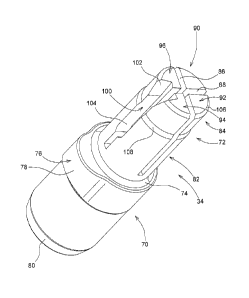
A coupler pin couples an output sleeve of rotary unit to an input member of a rotary sensor with interference fits. The coupler pin has a first part and a second part. A key groove is formed in an inner surface of a coupling bore in the output sleeve. The first part is received by the coupling bore, and the first part has a key member which is received by the key groove. The second part has a key slot formed therein. The input member has a key. The key has a slip fit with a first part of the key slot and has an interference fit with a second part of the key slot. The key projects inwardly from a wall of a coupling bore in the input member. The second part is divided into a plurality of sections by axially extending cross-cuts.


French Abstract

Une broche de couplage relie le manchon de sortie dune unité rotative à lélément dentrée dun capteur rotatif ayant des ajustements serrés. La broche de couplage comprend une première partie et une deuxième partie. On forme une rainure de clavette dans la surface interne dun tube de couplage taillé dans le manchon de sortie. Le tube de couplage peut accommoder la première partie et cette dernière comprend un élément de clavette qui sintroduit dans la rainure de clavette. La deuxième partie comprend une fente de clavette qui y est taillée. Lélément dentrée comprend une clavette. La clavette comprend un ajustement glissant ayant une première partie de la fente de clavette et un ajustement serré ayant une deuxième partie de la fente de clavette. La clavette saillit vers lintérieur à partir dun mur du tube de couplage constituant lélément dentrée. La deuxième partie est divisée en plusieurs zones par des coupes perpendiculaires axiales.

Claims

Note: Claims are shown in the official language in which they were submitted.


CLAIMS:
1. A coupler assembly for a rotary unit coupled to a sensor, said coupler
assembly
comprising:
a rotary sensor having an input member having a key on an inner portion
thereof; and
a coupler pin having a first part and a second part opposite the first part,
the
first part being coupled to the rotary unit with an interference fit, and the
second part
being coupled to the input member with an interference fit, the second part
comprising
a base and a tip projecting from the base, wherein the tip and base are
divided into a
plurality of sections by axially extending cross-cuts such that the sections
are radially
movable, the second part further comprising a key slot through at least part
of the tip
and the base, wherein the key is received by the key slot.
2. The coupler assembly of claim 1, wherein:
the rotary unit comprises an output sleeve with a coupling bore formed
therein;
a key groove is formed in an inner surface of the output sleeve; and
the first part of the coupler pin is received by the coupling bore, and the
first part
of the coupler pin having a key member which is received by the key groove.
3. The coupler assembly of claim 1, wherein:
the second part comprises a substantially cylindrical body with the base
having
a larger diameter base and the tip having a smaller diameter, the tip having a
slip fit
with the input member and the base having an interference fit with the input
member;
and
the key having a slip fit with the key slot in the tip and having an
interference fit
with the key slot in the base.
Date Recue/Date Received 2021-03-30

4. The coupler assembly of claim 3, wherein:
the tip and the base are divided into four sections by a pair of axially
extending
cross-cuts.
5. The coupler assembly of claim 1, wherein:
the input member has a coupling bore formed therein and the key projects
inwardly from a wall of the coupling bore.
6
Date Recue/Date Received 2021-03-30

Description

Note: Descriptions are shown in the official language in which they were submitted.


CA 02867825 2014-10-17
COUPLER ASSEMBLY
Field
The present disclosure relates to a coupler assembly for a rotary unit coupled
to
a sensor.
Background
To sense the rotary or angular position of a rotating mechanical part, it is
necessary to couple the rotating part to a rotary sensor. For example, a
grader type
work vehicle includes front and rear wheels which support a generally
longitudinal
frame. The frame member provides support for a rotatable working blade. A
rotary
motor controls the rotary position of the blade. An electrical sensor senses
the rotary
position or angle of the blade. Any mechanical hysteresis between the rotating
blade
and the sensor will have a negative effect on the accuracy of the blade
rotation system.
In such a configuration, it is desirable to use a coupler that does not allow
this type of
hysteresis.
Summary
According to an aspect of the present disclosure, a coupler assembly is
coupled
to a rotary sensor. The sensor has an input member, and the rotary unit
includes an
output sleeve with a coupling bore formed therein. A coupler pin has a first
part and a
second part. The first part is coupled to the rotary unit with an interference
fit, and the
second part is coupled to the input member with an interference fit. A key
groove is
formed in an inner surface of the output sleeve. The first part of the coupler
pin is
received by the coupling bore, and the first part of the coupler pin has a key
member
which is received by the key groove.
The second part has a cylindrical body having a larger diameter base and a
smaller diameter tip projecting from the base. The second part has a key slot
formed
therein. The tip has a slip fit with the input member and the base has an
interference fit
1

CA 02867825 2014-10-17
=
with the input member. The input member has a key. The key has a slip fit with
the key
slot in the tip and has an interference fit with the key slot in the base. The
input member
has a coupling bore formed therein and the key projects inwardly from a wall
of the
coupling bore.
The tip and the base are divided into a plurality of sections by axially
extending
cross-cuts. The key slot intersects with one of the cross-cuts. The sections
are
movable radially inwardly and outwardly towards and away from each other.
Brief Description of the Drawings
Fig. 1 is an exploded perspective view of a coupler assembly embodying the
invention;
Fig. 2 is a partially sectioned view of the assembly of Fig. 1;
Fig. 3 is a partially sectioned view of a portion of the assembly of Fig. 2;
Fig. 4 is a view taken along lines 4-4 of Fig. 1;
Fig. 5 is a perspective view of the coupler pin of Fig. 1;
Fig. 6 is a side view of the coupler pin of Fig. 5;
Fig. 7 is an end view of the coupler pin of Fig. 5;
Fig. 8 is an end view of the sensor of Fig. 4; and
Fig. 9 is a perspective view of the sensor of Fig. 8.
Detailed Description of the Drawings
Referring to Figs. 1-3, a coupler assembly 10 couples a rotary hydraulic motor
or
unit 12 to a rotary sensor 14. The motor 12 includes a housing 20 and a
manifold spool
22 which rotates in the housing 20. The manifold spool includes a main body
24, a
lower outer end 26 which is coupled to a grader blade (not shown), and a
hollow coupler
or output sleeve 28 which extends axially from the upper end of the main body
24. A
manifold cover 30 is fixed to the housing 20 and has a central opening 32
which
receives the sleeve 28.
A coupler pin 34 couples the sleeve 28 to the sensor 14. As best seen in Figs.
3
and 4, the sleeve 28 includes a uniform diameter cylindrical sleeve bore 40. A
key
grove 42 extends axially along one side of the bore 40. The bore 40 terminates
at
2

CA 02867825 2014-10-17
bottom wall 44, and preferably tapers from a slightly wider outer and to a
narrower inner
end.
Referring to Figs. 5-7, the coupler pin 34 includes a larger diameter first
portion
70 and a smaller diameter second portion 72 which projects axially from an end
of the
first portion 70 and which forms an annular shoulder 74. A key 76 projects
radially
outwardly from first portion 70 adjacent to the shoulder 74. The key has
curved outer
surface 78. A chamfer 80 is formed on the end first portion 70. As best seen
in Fig. 4,
the key 76 is received by the key grove 42. The first portion 70 and the key
76 are
received by the bore 40 and the key slot 42 with an interference fit.
The second portion 72 includes a larger diameter base 82 and a smaller
diameter tip 84. A pair of cross-cuts or slots 86 and 88 extend axially into
the tip 84 and
the base 82 of the second portion 72. The slots divide the second portion 72
into four
sections 90, 92, 94 and 96. A key slot 100 is formed between sections 94 and
96. Key
slot 100 has a larger axially outer end 102 and a smaller axially inner end
104. A
chamfer 106 is formed on the outer end of second portion 72 and a chamfer or
shoulder
108 is formed between base 82 and tip 84. As best seen in Fig. 7, the inner
end 104 of
the key slot 104 has a substantially rectangular shape. The slots 86 and 88
permit the
sections 90, 92, 94 and 96 to flex radially inwardly and outwardly, and the
key slot 100
intersects with the cross-cut 88.
Referring to Figs. 4, 8 and 9, the sensor 14 has an input sleeve 112 which
receives the second portion 72 of the coupler pin 34. The sleeve 112 includes
a
cylindrical inner wall 114. A key member 116 extends axially along the wall
114. The
key member 116 has a cross-sectional shape which is complementary with the
shape of
the key slot 104, and the key member 116 is slidably received by the key slot
104 so
that the input sleeve 112 will rotate with the coupler pin 34. The second
portion 72 is
received by the sleeve 112 with an interference fit, and the key member 166 is
received
by key slot 100 with an interference fit. As a result, the motor 12, the
coupler pin 34 and
the sensor input sleeve 112 will all rotate together without any free-play or
hysteresis
therebetween.
3

CA 02867825 2014-10-17
The result is a coupler assembly which provides an interference fit between a
rotating component and a sensor. The coupler is press fit into the rotating
component.
The sensor installation includes an interference fit keyway as well as a
radial
interference fit into the sensor. To promote an acceptable level of
interference fit, there
are two cross cuts down a portion of the coupler to allow the sensor side of
the coupler
to flex inward, limiting the force exerted on the sensor during installation.
The coupler
includes a lead in area to allow for installation on the mating component's
key prior to
the radial interference. The keyway on the coupler also has a chamfered area
to
promote alignment on the key during installation.
This coupler pin is a single, non-ferrous, piece that does not require extra
parts to
fasten to either component being coupled. It is also has an interference type
fit with
both components that it is coupled to. The cross-cuts permit an interference
fit while
limiting the force required to accomplish a zero mechanical hysteresis
coupling.
The non-keyed side of the coupler pin can be any shape that allows no
mechanical hysteresis between the coupler pin and the driving rotary unit. The
mating
component can be any type of part that requires input from the rotary unit.
The driving
mechanism can be any type of rotating component or rotary actuator.
While the disclosure has been illustrated and described in detail in the
drawings
and foregoing description, such illustration and description is to be
considered as
exemplary and not restrictive in character, it being understood that
illustrative
embodiments have been shown and described and that all changes and
modifications
that come within the spirit of the disclosure are desired to be protected. It
will be noted
that alternative embodiments of the present disclosure may not include all of
the
features described yet still benefit from at least some of the advantages of
such
features. Those of ordinary skill in the art may readily devise their own
implementations
that incorporate one or more of the features of the present disclosure and
fall within the
spirit and scope of the present invention as defined by the appended claims.
4

Representative Drawing
A single figure which represents the drawing illustrating the invention.
Administrative Status

For a clearer understanding of the status of the application/patent presented on this page, the site Disclaimer , as well as the definitions for Patent , Administrative Status , Maintenance Fee  and Payment History  should be consulted.

Administrative Status

Title Date
Forecasted Issue Date 2022-03-15
(22) Filed 2014-10-17
(41) Open to Public Inspection 2015-04-30
Examination Requested 2019-09-17
(45) Issued 2022-03-15

Abandonment History

There is no abandonment history.

Maintenance Fee

Last Payment of $210.51 was received on 2023-10-13


 Upcoming maintenance fee amounts

Description Date Amount
Next Payment if standard fee 2024-10-17 $347.00
Next Payment if small entity fee 2024-10-17 $125.00

Note : If the full payment has not been received on or before the date indicated, a further fee may be required which may be one of the following

  • the reinstatement fee;
  • the late payment fee; or
  • additional fee to reverse deemed expiry.

Patent fees are adjusted on the 1st of January every year. The amounts above are the current amounts if received by December 31 of the current year.
Please refer to the CIPO Patent Fees web page to see all current fee amounts.

Payment History

Fee Type Anniversary Year Due Date Amount Paid Paid Date
Application Fee $400.00 2014-10-17
Maintenance Fee - Application - New Act 2 2016-10-17 $100.00 2016-10-03
Maintenance Fee - Application - New Act 3 2017-10-17 $100.00 2017-10-04
Maintenance Fee - Application - New Act 4 2018-10-17 $100.00 2018-10-02
Request for Examination $800.00 2019-09-17
Maintenance Fee - Application - New Act 5 2019-10-17 $200.00 2019-09-30
Maintenance Fee - Application - New Act 6 2020-10-19 $200.00 2020-10-09
Maintenance Fee - Application - New Act 7 2021-10-18 $204.00 2021-10-11
Final Fee 2022-01-17 $306.00 2021-12-30
Maintenance Fee - Patent - New Act 8 2022-10-17 $203.59 2022-10-07
Maintenance Fee - Patent - New Act 9 2023-10-17 $210.51 2023-10-13
Owners on Record

Note: Records showing the ownership history in alphabetical order.

Current Owners on Record
DEERE & COMPANY
Past Owners on Record
None
Past Owners that do not appear in the "Owners on Record" listing will appear in other documentation within the application.
Documents

To view selected files, please enter reCAPTCHA code :


To view images, click a link in the Document Description column. To download the documents, select one or more checkboxes in the first column and then click the "Download Selected in PDF format (Zip Archive)" or the "Download Selected as Single PDF" button.

List of published and non-published patent-specific documents on the CPD .

If you have any difficulty accessing content, you can call the Client Service Centre at 1-866-997-1936 or send them an e-mail at CIPO Client Service Centre.


Document
Description 
Date
(yyyy-mm-dd) 
Number of pages   Size of Image (KB) 
Examiner Requisition 2020-12-14 3 148
Amendment 2021-03-30 8 291
Claims 2021-03-30 2 37
Final Fee 2021-12-30 3 75
Representative Drawing 2022-02-11 1 7
Cover Page 2022-02-11 1 39
Electronic Grant Certificate 2022-03-15 1 2,527
Abstract 2014-10-17 1 18
Description 2014-10-17 4 186
Claims 2014-10-17 3 95
Drawings 2014-10-17 7 147
Representative Drawing 2015-03-24 1 8
Cover Page 2015-04-09 2 42
Request for Examination 2019-09-17 2 43
Assignment 2014-10-17 3 85