Note: Descriptions are shown in the official language in which they were submitted.
CA 02867946 2016-02-01
OPTIMIZED REAL-TIME ANTISKID CONTROL INITIALIZATION FOR TRAVEL
SURFACES AS A FUNCTION OF WHEEL SPINUP
FIELD
The present disclosure relates to optimized antiskid control initialization.
In
particular, it relates to real-time antiskid control initialization for
vehicles on travel
surfaces a function of wheel spinup.
BACKGROUND
Currently, existing vehicle antiskid control initialization is optimized for
dry travel
surfaces due to the lack of input to indicate what the real-time travel
surface condition
(e.g., the coefficient of friction (p)) may be under other conditions, such as
during rain,
snow, ice, or contamination. This leads to a less than optimized
wet/contaminated
runway performance because the antiskid control will take longer to initialize
in other
than dry travel surface conditions. The present disclosure allows for the
selection of
the appropriate antiskid control initialization based on the real-time
condition of the
travel surface, for example detected during touchdown and de-rotation of the
wheels
of an aircraft.
1
CA 02867946 2016-02-01
SUMMARY
The present disclosure describes a method, system, and apparatus for
optimized antiskid control initialization for travel surfaces as a function of
wheel spinup
of a vehicle. In one or more embodiments, a method for optimizing real-time
antiskid
control initialization for a vehicle on a travel surface involves determining,
with at least
one processor, when at least one wheel of the vehicle touches ground. The
method
further involves calculating, with the at least one processor, a rate of wheel
spin up for
at least one wheel. Also, the method involves determining, with the at least
one
processor, whether the rate of wheel spin up exceeds a wheel spin up rate
threshold.
In addition, the method involves applying, with at least one brake for the at
least one
wheel, a high level of brake force, when the rate of wheel spin up exceeds the
wheel
spin up rate threshold. Further, the method involves applying, with at least
one brake
for at least one wheel, a low level of brake force, when the rate of wheel
spin up does
not exceed the wheel spin up rate threshold.
In one or more embodiments, the determining of when at least one wheel of the
vehicle touches the ground may involve determining, with the at least one
wheel
sensor, a weight on at least one wheel; and determining, with the at least one
processor, whether the weight on at least one wheel exceeds a weight
threshold.
2
CA 02867946 2016-02-01
In at least one embodiment, the weight threshold may be related to a size of
the
vehicle.
In at least one embodiment, the method may further involve measuring, with at
least one wheel sensor, a speed of at least one wheel.
In some embodiments, the calculating of the rate of wheel spin up may involve
at least one processor using the speed of at least one wheel.
In one or more embodiments, the wheel spin up rate threshold may be around
1000 feet per second squared (ft/sec2).
In at least one embodiment, the high level of brake force may be about 1500 to
3000 pounds per square inch (psi).
In some embodiments, the low level of brake force may be about 300 to 1500
psi.
In one or more embodiments, the vehicle may be an aircraft or a space plane.
In some embodiments, at least one brake may be a forward brake and/or an aft
brake.
3
CA 02867946 2016-02-01
The present disclosure also describes a method for optimizing real-time
antiskid control initialization for a vehicle on a travel surface. The method
involves
determining, with at least one processor, a time when at least one wheel of
the vehicle
touches ground; calculating, with the at least one processor, a rate of wheel
spin up
for the at least one wheel; determining, with the at least one processor,
whether the
rate of wheel spin up exceeds a wheel spin up rate threshold. The method
further
involves applying, with at least one brake for the at least one wheel, a high
level of
brake force, when the rate of wheel spin up exceeds the wheel spin up rate
threshold;
and applying, with the at least one brake for the at least one wheel, a low
level of
brake force, when the rate of wheel spin up does not exceed the wheel spin up
rate
threshold.
4
CA 02867946 2016-02-01
The determining of the time when the at least one wheel of the vehicle touches
the ground may include determining, with at least one wheel sensor, a weight
on the
at least one wheel; and determining, with the at least one processor, whether
the
weight on the at least one wheel exceeds a weight threshold.
The weight threshold may be related to a size of the vehicle.
The method further may include measuring, with at least one wheel sensor, a
speed of the at least one wheel.
The calculating of the rate of wheel spin up may include the at least one
processor using the speed of the at least one wheel.
The wheel spin up rate threshold may be around 1000 feet per second squared
(ft/sec2).
The high level of brake force may be about 1500 to 3000 pounds per square
inch (psi).
5
CA 02867946 2016-02-01
The low level of brake force may be about 300 to 1500 psi.
The vehicle may be one of an aircraft and a space plane.
The at least one brake may be at least one of a forward brake and an aft
brake.
Each of these characteristics may enhance operation or improve performance
of a vehicle or braking system.
The present disclosure also provides for a system for optimized antiskid
control
initialization for a vehicle. The system includes at least one processor to
determine a
time when at least one wheel of the vehicle touches ground, to calculate a
rate of
wheel spin up for the at least one wheel, and to determine whether the rate of
wheel
spin up exceeds a wheel spin up rate threshold. The system also includes at
least one
brake, for the at least one wheel, to apply a high level of brake force when
the rate of
wheel spin up exceeds the wheel spin up rate threshold, and to apply a low
level of
brake force when the rate of wheel spin up does not exceed the wheel spin up
rate
threshold.
Each of these characteristics may enhance operation or improve performance
of a vehicle or braking system.
The features and functions disclosed herein can be achieved independently in
various embodiments of the present disclosure or may be combined in yet other
embodiments.
6
CA 02867946 2014-10-22
DRAWINGS
These and other features, aspects, and advantages of the present disclosure
will become better understood with regard to the following description,
appended
claims, and accompanying drawings where:
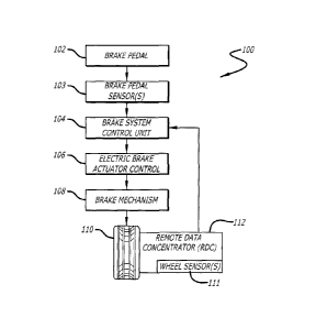
FIG. 1 is a schematic representation of a portion of an electric brake system
suitable for use in an aircraft (i.e. a vehicle) that may be employed by the
disclosed
system for optimized antiskid control initialization for dry and wet runways
as a
function of wheel spinup, in accordance with at least one embodiment of the
present
invention.
FIG. 2 is a schematic representation of a brake control architecture suitable
for
use in an electric brake system for an aircraft (i.e. a vehicle) that may be
employed by
the disclosed system for optimized antiskid control initialization for dry and
wet
runways as a function of wheel spinup, in accordance with at least one
embodiment of
the present invention.
FIG. 3 is a graph showing exemplary wheel speed for an aircraft as a function
of time for dry runway conditions and for wet/contaminated runway conditions,
in
accordance with at least one embodiment of the present invention.
FIG. 4 is a graph illustrating exemplary brake clamping force for an aircraft
as a
function of time for dry runway conditions and for wet/contaminated runway
conditions,
in accordance with at least one embodiment of the present invention.
FIG. 5 is a flow chart for the disclosed method for optimized antiskid control
initialization for dry and wet runways as a function of wheel spinup, that
uses the rate
of wheel spin up to estimate the runway condition, in accordance with at least
one
embodiment of the present invention.
FIG. 6 is a flow chart for the disclosed method for optimized antiskid control
initialization for dry and wet runways as a function of wheel spinup, that
uses the time
of wheel spin up to estimate the runway condition, in accordance with at least
one
embodiment of the present invention.
7
CA 02867946 2014-10-22
DESCRIPTION
The methods and apparatus disclosed herein provide an operative system for
optimized, real-time antiskid control initialization for travel surfaces in
varying
conditions, as a function of data for wheel spinup of the vehicle. The
disclosed system
provides a solution that monitors the wheel speed data of the vehicle, for
example,
during the touchdown and de-rotation portion of an aircraft landing (i.e. the
lowering of
the nosewheel of the aircraft to the runway following the main gear
touchdown), and
then based on that information, selects the appropriate antiskid control
initialization for
the condition of the travel surface.
As previously mentioned above, existing vehicle antiskid control
initialization is
optimized for dry travel surfaces, due to the lack of input to indicate the
real-time
conditions. Wet and/or contaminated travel surfaces have lower friction
coefficients.
Failure to adjust for varying surface conditions can result in a delay in the
initialization
of the antiskid controller, which in turn can result in releasing brake
pressure too soon
and/or failing to adequately control excessive wheel skid.
The system of the invention allows for the determination of the appropriate
antiskid control initialization-based on the real-time condition of a travel
surface (e.g.,
a wet or dry runway) before braking, detected by wheel spinup on the surface,
for
example during touchdown and de-rotation of an aircraft.
In particular, the system of the invention determines real-time travel surface
conditions (e.g., whether the surface is wet or dry) by using wheel speed
data. By
determining the real-time surface conditions based on the wheel speed data,
the
system allows for the ability to select for the appropriate antiskid control
initialization
on a real-time, "as needed" basis. As such, the system is able to determine
travel
surface conditions (e.g., characteristics of a runway surface) in order to
properly
initiate antiskid action, and to inform the vehicle's driver or pilot or
autopilot, and
vehicle controls accordingly. Thus, the disclosed system enhances the safety
of
landing, improves the antiskid control system performance, and increases the
life of
the tires of a vehicle, thereby decreasing needed maintenance expense and
time.
8
CA 02867946 2014-10-22
In the following description, numerous details are set forth in order to
provide a
more thorough description of the system. It will be apparent, however, to one
skilled
in the art, that the disclosed system may be practiced without these specific
details. In
the other instances, well known features have not been described in detail so
as not to
unnecessarily obscure the system.
Embodiments of the invention may be described herein in terms of functional
and/or logical block components and various processing steps. It should be
appreciated that such block components may be realized by any number of
hardware,
software, and/or firmware components configured to perform the specified
functions,
including "off the shelf" components. For example, an embodiment of the
invention
may employ various integrated circuit components, e.g., memory elements,
digital
signal processing elements, logic elements, look-up tables, or the like, which
may
carry out a variety of functions under the control of one or more
microprocessors or
other control devices. In addition, those skilled in the art will appreciate
that
embodiments of the present invention may be practiced in conjunction with a
variety of
different aircraft brake systems and aircraft configurations, and that the
system
described herein is merely one example embodiment of the invention.
For the sake of brevity, conventional techniques and components related to
signal processing, aircraft brake systems, brake system controls, and other
functional
aspects of the systems (and the individual operating components of the
systems) may
not be described in detail herein. Furthermore, the connecting lines shown in
the
various figures contained herein are intended to represent example functional
relationships and/or physical couplings between the various elements. It
should be
noted that many alternative or additional functional relationships or physical
connections may be present in an embodiment of the invention.
The following description refers to structural elements or nodes or features
being "coupled" together. As used herein, unless expressly stated otherwise,
"coupled" means that one element/node/feature is directly or indirectly joined
to (or
directly or indirectly communicates with) another element/node/feature, and
not
9
CA 02867946 2014-10-22
necessarily mechanically. Thus, although the schematic representations shown
in the
figures depict example arrangements of elements, additional intervening
elements,
devices, features, or components may be present in an embodiment of the
invention.
FIG. 1 is a schematic representation of a portion of an electric brake system
100 of the invention suitable for use in an aircraft (not shown). Electric
brake system
100 includes a brake pedal 102, a brake system control unit (BSCU) 104 coupled
to
brake pedal 102, an electric brake actuator control (EBAC) 106 coupled to BSCU
104,
and a brake mechanism 108 coupled to EBAC 106. Brake mechanism 108
corresponds to at least one wheel 110 of the aircraft. Electric brake system
100 may
also include an axle-mounted remote data concentrator (RDC) 112 coupled to
wheel
110. Briefly, BSCU 104 reacts to manipulation of brake pedal 102 and generates
control signals that are received by EBAC 106. In turn, EBAC 106 generates
brake
mechanism control signals that are received by brake mechanism 108. In turn,
brake
mechanism 108 actuates to slow the rotation of wheel 110. These features and
components are described in more detail below.
Electric brake system 100 can be applied to any number of electric braking
configurations for an aircraft, and electric brake system 100 is depicted in a
simplified
manner for ease of description. An embodiment of electric brake system 100 may
include a left subsystem architecture and a right subsystem architecture,
where the
terms "left" and "right" refer to the port and starboard of the aircraft,
respectively. In
practice, the two subsystem architectures may be independently controlled in
the
manner described below. In this regard, an embodiment of electric brake system
100
as deployed may include a left brake pedal, a right brake pedal, a left BSCU,
a right
BSCU, any number of left EBACs coupled to and controlled by the left BSCU, any
number of right EBACs coupled to and controlled by the right BSCU, a brake
mechanism for each wheel (or for each group of wheels), and an RDC for each
wheel
(or for each group of wheels). In operation, the electric brake system can
independently generate and apply brake actuator control signals for each wheel
of the
aircraft or concurrently for any group of wheels.
CA 02867946 2016-02-01
Brake pedal 102 is configured to provide pilot input to electric brake system
100. The pilot physically manipulates brake pedal 102, resulting in deflection
or
movement (i.e., some form of physical input) of brake pedal 102. This physical
deflection is measured from its natural position by a hardware servo or an
equivalent
component, converted into a BSCU pilot command control signal by a transducer
or
an equivalent component, and sent to BSCU 104. The BSCU pilot command control
signal may convey brake pedal sensor data that may include or indicate the
deflection
position for brake pedal 102, the deflection rate for brake pedal 102, a
desired braking
condition for brake mechanism 108, or the like.
An embodiment of electric brake system 100 may use any number of BSCUs
104. For ease of description, this example includes only one BSCU 104. BSCU
104 is
an electronic control unit that has embedded software that digitally computes
EBAC
control signals that represent braking commands. The electrical/software
implementation allows further optimization and customization of braking
performance
and brake onset if needed for the given aircraft deployment.
BSCU 104 may be implemented or performed with a general purpose
processor, a content addressable memory, a digital signal processor, an
application
specific integrated circuit, a field programmable gate array, any suitable
programmable logic device, discrete gate or transistor logic, discrete
hardware
components, or any combination thereof, designed to perform the functions
described
herein. A processor may be realized as a microprocessor, a controller, a
microcontroller, or a state machine. A processor may also be implemented as a
combination of computing devices, e.g., a combination of a digital signal
processor
and a microprocessor, a plurality of microprocessors, one or more
microprocessors in
conjunction with a digital signal processor core, or any other such
configuration. In one
embodiment, the BSCU 104 employs a computer processor (such as a PowerPC 555)
that hosts software and provides external interfaces for the software.
BSCU 104 monitors various vehicle inputs to provide control functions such as,
without limitation: pedal braking; parking braking; automated braking; and
gear retract
braking. It should be noted that BSCU 104 is always on. In addition, BSCU 104
blends
11
CA 02867946 2016-02-01
antiskid commands (which could be generated internally or externally from BSCU
104)
to provide enhanced control of braking. BSCU 104 obtains pilot command control
signals from brake pedal 102 (i.e. the pilot controls the brake pedals that
the BSCU
104 senses to control the deceleration of the vehicle), along with wheel data
(e.g.,
wheel speed, rotational direction, tire pressure, etc.) from RDC 112, as
described in
more detail below. As such, BSCU 104 continually monitors any movement of
brake
pedal 102 along with the speed of wheel 110. It should be noted that although
relatively independent of BSCU 104, use of brake pedal 102 is required in
order for
wheel 110 to skid. In addition, brake pedal 102 has to be applied with a brake
pressure greater than the brake pressure required for wheel 110 to skid before
antiskid initializes (e.g., before antiskid commands are generated).
Also, BSCU 104 processes its input signals and generates one or more EBAC
control signals that are received by EBAC 106. In practice, BSCU 104 transmits
the
EBAC control signals to EBAC 106 via a digital data bus. In a generalized
architecture
(not shown), each BSCU can generate independent output signals for use with
any
number of EBACs under its control.
BSCU 104 may be coupled to one or more associated EBACs 106. EBAC 106
may be implemented, performed, or realized in the manner described above for
BSCU
104. In one embodiment, EBAC 106 is realized with a computer processor (such
as a
PowerPC 555) that hosts software, provides external interfaces for the
software, and
includes suitable processing logic that is configured to carry out the various
EBAC
operations described herein. EBAC 106 obtains EBAC control signals from BSCU
104, processes the EBAC control signals, and generates the brake mechanism
control
signals (brake actuator signals) for brake mechanism 108.
Notably, the functionality of BSCU 104 and EBAC 106 may be combined into a
single processor-based feature or component. In this regard, BSCU 104, EBAC
106,
or the combination thereof can be considered to be a brake control
architecture for
electric brake system 100. Such a brake control architecture includes suitably
12
CA 02867946 2014-10-22
configured processing logic, functionality, and features that support the load
alleviation
and brake control operations described herein.
Wheel 110 may include an associated brake mechanism 108. EBAC 106
controls brake mechanism 108 to apply, release, modulate, and otherwise
control the
actuation of one or more components of brake mechanism 108. In this regard,
EBAC
106 generates the brake mechanism control signals in response to the
respective
EBAC control signals generated by BSCU 104. The brake mechanism control
signals
are suitably formatted and arranged for compatibility with the particular
brake
mechanism 108 utilized by the aircraft. In practice, the brake mechanism
control
signals may be regulated to carry out anti-skid and other braking maneuvers.
Those
skilled in the art are familiar with aircraft brake mechanisms and the general
manner in
which they are controlled, and such known aspects will not be described in
detail here.
Electric brake system 100 may include or communicate with one or more
sensors 111 for wheel 110. These sensors 111 are suitably configured to
measure
wheel data (wheel speed, direction of wheel rotation, tire pressure,
wheel/brake
temperature, etc.) for wheel 110, where the wheel data can be utilized by
electrical
braking system 100. RDC 112 is generally configured to receive, measure,
detect, or
otherwise obtain data for processing and/or transmission to another component
of
electric brake system 100. Here, RDC 112 is coupled to (or is otherwise
associated
with) wheel 110, and RDC 112 is configured to collect and transmit its wheel
data to
BSCU 104. The digital data communication bus or buses on the aircraft may be
configured to communicate the wheel data from RDC 112 to BSCU 104 using any
suitable data communication protocol and any suitable data transmission
scheme. In
an alternate embodiment, RDC 112 may be configured to communicate the wheel
data to EBAC 106. In yet another embodiment, RDC 112 may be configured to
communicate the wheel data to BSCU 104 and EBAC 106.
In this example, electric brake system 100 is suitably configured to control
the
actuation of brake mechanism 108 in response to the wheel data. In particular,
electric
13
CA 02867946 2014-10-22
brake system 100 is configured to control the actuation of brake mechanism 108
in
response to a wheel speed value, which indicates the current speed of the
aircraft.
Electric brake system 100 can be utilized to alleviate dynamic structural
loads
(e.g., landing gear loads) during high effort braking of the aircraft.
Electric brake
system 100 generally commands brake mechanism 108 to generate brake torque in
a
manner that is related to the amount that brake pedal 102 is deflected by the
pilot.
This control can take into account the deflection position of brake pedal 102,
the
deflection rate of brake pedal 102, and/or the speed at which the aircraft is
traveling to
modify the actuation of brake mechanism 108 such that the desired brake torque
is
obtained at a suitable rate that does not develop high peak dynamic loads.
This allows
the aircraft landing gear to be designed with less weight and bulk, which
benefits
aircraft performance. In one embodiment, electric brake system 100 uses
sensors 103
at brake pedal 102 to measure the deflection and deflection rate of brake
pedal 102.
BSCU 104 processes these inputs to reduce the initial onset rate of brake
application,
which in turn reduces the peak brake load that has to be absorbed by the
landing gear
structure. The brake control laws can be tuned for the particular model of
aircraft,
static, dynamic, or operational characteristics of the aircraft, and/or
static, dynamic, or
operational characteristics of brake mechanism 108.
FIG. 2 is a schematic representation of a brake control architecture 200
suitable
for use in an electric brake system for an aircraft. Electric brake system 100
may
employ an embodiment of brake control architecture 200. For example, brake
control
architecture 200 may be implemented or realized in BSCU 104 and/or EBAC 106.
Brake control architecture 200 may include, without limitation: a processor
202 having
suitably configured processing logic; an appropriate amount of memory 204; and
a
brake mechanism control signal generator 206. Brake control architecture 200
may,
but need not, include a brake application profile generator 208. These
elements may
be coupled together using a data communication bus 209 or any suitably
configured
interconnection architecture or arrangement. In this embodiment, brake control
14
CA 02867946 2014-10-22
architecture 200 is configured to obtain and process brake pedal sensor data
210 and
wheel speed data 212 in the manner described in more detail below.
Processor 202 may be implemented, performed, or realized in the manner
described above for BSCU 104. The processing logic corresponding to processor
202
is designed to carry out various operations and functions associated with the
electric
brake control scheme described herein. Furthermore, a method or algorithm (or
portions thereof) described in connection with the embodiments disclosed
herein may
be embodied directly in hardware, in firmware, in a software module executed
by
processor 202, or in any practical combination thereof. A software module may
reside
in memory 204, which may be realized as one or more physical components having
RAM memory, flash memory, ROM memory, EPROM memory, EEPROM memory,
registers, a hard disk, a removable disk, a CD-ROM, or any other form of
storage
medium known in the art. In this regard, memory 204 can be coupled to
processor 202
such that processor 202 can read information from, and write information to,
memory
204. In the alternative, memory 204 may be integral to processor 202. As an
example,
processor 202 and memory 204 may reside in an ASIC.
Memory 204 may be configured to store at least one brake application profile
214 for the aircraft. Brake application profile 214 influences the manner in
which the
brake mechanism is actuated. Brake application profile 214 may be
predetermined
and programmed into brake control architecture 200 or generated in real-time
by
brake application profile generator 208. In the former situation, brake
application
profile 214 may be based upon static, dynamic, aerodynamic, operational,
and/or
other characteristics of the aircraft (e.g., the mass of the aircraft and the
typical
landing speed of the aircraft) and/or based upon static, dynamic, operational
and/or
other characteristics of the electric brake system or brake mechanism (e.g.,
the
response time of the control elements, the maximum achievable brake torque,
and the
typical range of brake torque). In the latter situation, the optional brake
application
profile generator 208 may be utilized to generate brake application profile
214
dynamically in response to brake pedal sensor data 210 and/or in response to
wheel
CA 02867946 2014-10-22
speed data 212. The operation of brake application profile generator 208 may
also be
influenced by aircraft characteristics and/or brake mechanism characteristics
as
mentioned above. In practice, brake application profile generator 208 may be
realized
in the processing logic of processor 202.
FIG. 3 is a graph 300 showing exemplary wheel speed for an aircraft as a
function of time for dry runway conditions 310 and for wet/contaminated runway
conditions 320, in accordance with at least one embodiment of the present
disclosure.
In this figure, the y-axis denotes wheel speed, and the x-axis denotes time.
In
particular, the graph 300 shows the wheel speed as a function of time for dry
runway
conditions 310 and for wet/contaminated runway conditions 320 starting from
the time
T1 the aircraft touches down onto the runway with an initial wheel speed of Y1
(i.e.
zero) to the time T2 when reaching the aircraft ground speed Y2 without
slippage.
FIG. 4 is a graph 400 illustrating exemplary brake clamping force for an
aircraft
as a function of time for dry runway conditions 410 and for wet/contaminated
runway
conditions 420, in accordance with at least one embodiment of the present
invention.
In this figure, the y-axis denotes brake clamping force, and the x-axis
denotes time.
Specifically, the graph 400 shows the brake clamping force as a function of
time for
dry runway conditions 410 and for wet/contaminated runway conditions 420
starting
from the time T1 the aircraft touches down onto the runway. The brake clamping
force
antiskid is initialized to a lower level F1 for wet/contaminated runway
conditions.
Conversely, the brake clamping force antiskid is initialized to a higher level
F2 for dry
runway conditions.
FIG. 5 is a flow chart for the disclosed method 500 for optimized antiskid
control
initialization for dry and wet travel surfaces as a function of wheel spinup,
that uses
the rate of wheel spin up to estimate the surface condition, in accordance
with at least
one embodiment of the present invention. At the start 510 of the method 500,
at least
one processor determines when at least one wheel of the vehicle (e.g., an
aircraft)
touches the ground by determining, with at least one wheel sensor, the weight
on at
least one wheel and by determining, with at least one processor, whether the
weight
16
CA 02867946 2014-10-22
on at least one wheel exceeds a weight threshold 520. In one or more
embodiments,
the weight threshold is related to the size of the vehicle.
If the processor determines that the weight on at least one wheel does not
exceed the weight threshold, the method 500 returns to the start 510. However,
if the
processor determines that the weight on at least one wheel does exceed the
weight
threshold, the method 500 proceeds to step 530.
Then, at step 530, at least one wheel sensor measures the speed of at least
one wheel (e.g., in feet per seconds (ft/sec)) 530. At least one processor
then
calculates a rate of wheel spin up for at least one wheel (e.g., in feet per
seconds
squared (ft/sec2)) by using the measured speed of at least one wheel 540.
At least one processor then determines whether the calculated rate of wheel
spin up exceeds a wheel spin up rate threshold 550. In one or more
embodiments,
the wheel spin up rate threshold is around 1000 ft/ sec2. If it is determined
that the
rate of wheel spin up does not exceed the wheel spin up rate threshold, it is
assumed
that the runway is wet and at least one brake will apply a low level of brake
force for at
least one wheel 560. In one or more embodiments, the low level of brake force
is
about 300 to 1500 pounds per square inch (psi). It should be noted that these
are
typical values for brake pressure reduced by the antiskid system, if it is
determined
that the runway is wet. In other embodiments, various different values for the
low level
of brake force may be utilized.
However, if it is determined that the rate of wheel spin up does exceed the
wheel spin up rate threshold, it is assumed that the runway is dry and at
least one
brake will apply a high level of brake force for at least one wheel 570. In
one or more
embodiments, the high level of brake force is about 1500 to 3000 psi. It
should be
noted that these are typical values for brake pressure applied by the antiskid
system, if
it is determined that the runway is dry. In other embodiments, various
different values
for the high level of brake force may be used. Also, it should be noted that
in one or
more embodiments, at least one brake is a forward brake and/or an aft brake.
Then,
the method 500 ends 580.
17
CA 02867946 2014-10-22
FIG. 6 is a flow chart for the disclosed method 600 for optimized antiskid
control
initialization for dry and wet runways as a function of wheel spinup, that
uses the time
of wheel spin up to estimate the runway condition, in accordance with at least
one
embodiment of the present disclosure. At the start 605 of the method 600, at
least
one processor determines when at least one wheel of the vehicle (e.g., an
aircraft)
touches the ground 615 by determining, with at least one wheel sensor, the
weight on
at least one wheel and by determining, with at least one processor, whether
the weight
on at least one wheel exceeds a weight threshold 610. In some embodiments, the
weight threshold is related to the size of the vehicle.
If the processor determines that the weight on at least one wheel does not
exceed the weight threshold, the method 600 returns to the start 605. However,
if the
processor determines that the weight on at least one wheel does exceed the
weight
threshold, the method 600 proceeds to step 615.
At step 615, the processor determines the time T1 when at least one wheel of
the vehicle touches the ground, which is indicated by the weight threshold
being
exceeded. Then, at least one wheel sensor measures the speed of at least one
wheel
(e.g., ft/sec) 620. At least one processor then determines the ground speed
(e.g.,
ft/sec). 625. Then, at least one processor determines wheel slippage (e.g.,
ft/sec) by
calculating the wheel speed minus the ground speed 630.
At least one processor then determines if the wheel slippage is equal to zero
635. If it is determined that the wheel slippage is not equal to zero, this
indicates that
the wheel speed is not equal to the ground speed, and the method 600 returns
to step
630. However, if it is determined that the wheel slippage is equal to zero,
this
indicates that the wheel speed is equal to the ground speed, and the method
600
proceeds to step 640.
At step 640, at least one processor determines the time T2 when the wheel
speed is equal to the ground speed 640. Then, at least one processor
determines a
total time T by calculating the time T2 minus the time T1 645.
18
CA 02867946 2014-10-22
At least one processor then determines whether the calculated total time T
exceeds a time threshold 650. In one or more embodiments, the time threshold
is
around 0.5 seconds (sec). If it is determined that the total time T does not
exceed the
time threshold, it is assumed that the runway is wet and at least one brake
will apply a
low level of brake force for at least one wheel 655. In at least one
embodiment, the
low level of brake force is about 300 to 1500 pounds per square inch (psi).
However, if
it is determined that the total time T does exceed the time threshold, it is
assumed that
the travel surface is dry and at least one brake will apply a high level of
brake force for
at least one wheel 660. In some embodiments, the high level of brake force is
about
1500 to 3000 psi. Then, the method 600 ends 665.
It should be noted that the vehicle employed by the disclosed system, method,
and apparatus for optimized antiskid control initialization for travel
surfaces in variable
conditions as a function of wheel spinup may be an airborne vehicle. In some
embodiments, the airborne vehicle may be an aircraft or a space plane. For
these
embodiments, the forward and aft brakes are associated with at least one
landing gear
truck containing at least one wheel.
It should also be noted that in some
embodiments, a vehicle speed sensor(s) (e.g., a sensor(s) that measures linear
velocity) may be used instead or in conjunction with a wheel speed sensor(s)
(e.g., a
sensor(s) that measures rotational velocity). For these embodiments, a vehicle
speed
threshold value may be utilized as well.
Although particular embodiments have been shown and described, it should be
understood that the above discussion is not intended to limit the scope of
these
embodiments. While embodiments and variations of the many aspects of the
invention have been disclosed and described herein, such disclosure is
provided for
purposes of explanation and illustration only.
Thus, various changes and
modifications may be made without departing from the scope of the claims.
Where methods described above indicate certain events occurring in certain
order, those of ordinary skill in the art having the benefit of this
disclosure would
recognize that the ordering may be modified and that such modifications are in
19
CA 02867946 2016-02-01
accordance with the variations of the present disclosure. Additionally, parts
of
methods may be performed concurrently in a parallel process when possible, as
well
as performed sequentially. In addition, more parts or less part of the methods
may be
performed.
Accordingly, embodiments are intended to exemplify alternatives,
modifications,
and equivalents that may fall within the scope of the claims.
Although certain illustrative embodiments and methods have been disclosed
herein, it can be apparent from the foregoing disclosure to those skilled in
the art that
variations and modifications of such embodiments and methods can be made
without
departing from the scope of the art disclosed. Many other examples of the art
disclosed exist, each differing from others in matters of detail only.
Accordingly, it is
intended that the art disclosed shall be limited only to the extent required
by the
appended claims and the rules and principles of applicable law.