Note: Descriptions are shown in the official language in which they were submitted.
CA 02867986 2014-09-19
- 1 -
DESCRIPTION
TITLE OF INVENTION
EQUIPMENT SYSTEM FOR PRODUCING PIERCING-ROLLING PLUG
TECHNICAL FIELD
[0001]
The present invention relates to an equipment system for producing a
piercing-rolling plug to be used in a piercing-rolling mill (hereinafter, also
referred to
simply as a "piercer") that produces a seamless steel tube/pipe, particularly
to an
equipment system for producing a piercing-rolling plug having a film formed by
performing arc-spraying of iron wires on a surface of a plug base metal.
BACKGROUND ART
[0002]
A seamless steel tube/pipe is produced by the Mannesmann tube-making
process. The Mannesmann tube-making process includes the following steps:
(1) piercing-rolling a starting material (round billet) heated at a
predetermined
temperature into a hollow shell by using a piercer;
(2) elongation-rolling the hollow shell by an elongation rolling mill (e.g.
mandrel mill); and
(3) carrying out diameter adjusting rolling on the elongation-rolled hollow
shell to have a predetermined outer diameter and wall thickness by using a
diameter
adjusting rolling mill (e.g. a stretch reducer).
[0003]
In the piercing-rolling by using the piercer, a plug is used as a piercing
tool.
This plug is mounted to a front end of a core bar so as to pierce a billet
heated at a
high temperature of approximately 1200 C; thus the plug is subjected to a
hostile
environment with a high surfacial pressure and a high temperature. In general,
the
plug includes a base metal made of hot working tool steel, and a film of oxide
scale
is formed on a surface of the base metal through a heating process in advance
for the
purpose of protection of the base metal, and thereafter the plug is used in
the
CA 02867986 2014-09-19
- 2 -
piercing-rolling. During the piercing-rolling, the scale film on the surface
of the
plug insulates heat transfer from the billet to the base metal of the plug,
and also
prevents seizing between the billet and the plug.
[0004]
Repetitive piercing-rolling of such a plug having the scale film causes a
gradual abrasion of the scale film. The abrasion of the scale film
deteriorates
thermal insulation effect of the film, resulting in increase in temperature of
the plug
during the piercing, so that melting-incurred metal loss and deformation by
heat are
likely to be caused to the plug base metal. If the scale film is exhausted,
and the
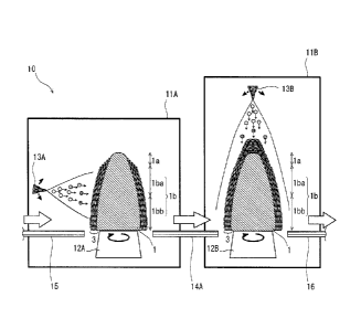
plug base metal comes into direct contact with the billet, seizing is caused,
so as to
generate flaws on an internal surface of a steel tube/pipe. Consequently, the
plug
becomes unusable at the moment when the film is exhausted, and its durability
life is
expired.
[0005]
Particularly in production of a seamless steel tube/pipe made of high alloy
steel such as high Cr steel containing Cr of 9% or more, Ni-based alloy, and
stainless
steel, significant abrasion of the scale film on the surface of the plug is
generated
during the piercing-rolling, so that the durability life of the plug becomes
significantly reduced. For example, in the case of piercing stainless steel,
the scale
film on the surface of the plug becomes worn away through two or three passes
(the
number of times of continuous piercing rolling), and the durability life of
this plug is
expired. This requires a frequent replacement of the plug, which deteriorates
the
production efficiency. In production of a seamless steel tube/pipe of high
alloy
steel, it is required to enhance the durability life of the plug during the
piercing-
rolling, thereby enhancing the production efficiency of the steel tube/pipe.
[0006]
To satisfy such a requirement, as an example of the film formed on the
surface of the plug base metal, Patent Literature 1 discloses such a plug
having a film
containing oxide and Fe formed on the surface of the plug base metal by
performing
arc-spraying of iron wires, instead of using the scale film formed through
heat
treatment. Since the plug having the arc-sprayed film has a film containing
oxide
and Fe on the surface of the plug, this plug is excellent in thermal
insulation
CA 02867986 2014-09-19
- 3 -
performance and seizing prevention, so that enhancement of the durability life
of the
plug is likely to be achieved.
[0007]
Patent Literature 1 discloses an equipment system of producing (reproducing)
a plug having an arc-sprayed film by forming the film containing oxide and Fe
on a
surface of a base metal of the plug in such a manner that, after shotblasting
is applied
onto the surface of the plug, molten material is sprayed from arc-spray guns
onto the
surface of the plug base metal while a turntable on which the plug is mounted
is
being rotated. In this equipment system, the spray guns are so disposed as to
face a
tip end portion, a front-half of the body portion, and a rear-half of the body
portion of
the surface of the plug base metal, and forms the arc-sprayed film by
operating all
the spray guns at the same time, thereby reducing time required for forming
the film
compared to the case of using a single spray gun to form the arc-sprayed film
across
the entire surface of the plug base metal, which results in enhancement of
production
efficiency of the plug.
[0008]
Unfortunately, even in the plug having the arc-sprayed film formed by using
the conventional equipment system disclosed in Patent Literature 1, there
occurs
separation of the film if a billet length to be pierced is long, or if a
billet having
elevated-temperature strength is used. As such, there is still room for
further
improvement in securing the steadily enhanced durability life of the plug, and
thus it
has been strongly desired to produce a piercing-rolling plug that can realize
the
above improvement.
CITATION LIST
PATENT LITERATURE
[0009]
Patent Literature 1: Japanese Patent No. 4279350
SUMMARY OF INVENTION
TECHNICAL PROBLEM
[0010]
CA 02867986 2014-09-19
- 4 -
An object of the present invention, which has been made in order to solve the
problems according to the conventional art, is to provide an equipment system
for
producing a r piercing-rolling plug having a film containing oxide and Fe
formed on
a surface of the plug base metal by performing arc-spraying of iron wires, and
the
equipment system has the following features of:
(1) maintaining production efficiency of the plug at a high level; and
(2) securing steady enhancement of the durability life of the plug even if a
billet length to be pierced is long, or even if a billet having high elevated-
temperature
strength is used.
SOLUTION TO PROBLEM
[0011]
The summary of the present invention is as follows.
[0012]
Provided is an equipment system for producing a piercing-rolling plug to be
used for producing a seamless steel tube/pipe, and
the equipment system for producing the r piercing-rolling plug comprises:
a shotblasting device for applying shotblasting on a surface of the plug; and
an arc-spraying device for performing arc-spraying of iron wires on a surface
of a base metal of the plug to which the shotblasting is applied, so as to
form a film
containing oxide and Fe thereon.
The arc-spraying device includes plural spraying booths each of which is used
to separately form part of the film in turn in each of sections into which the
surface
of the base metal of the plug is divided along an axial direction of the plug.
[0013]
In this equipment system, it is preferable that an arc-spray gun for melting
the
iron wires by an arc, and spraying molten material thereof onto the surface of
the
base metal of the plug is disposed in each arc-spraying booth, and the arc-
spraying is
carried out while an intersection angle between the center line of a spraying
stream
from the arc-spray gun and the surface of the base metal of the plug is
maintained in
a range of 35 degrees to 90 degrees.
[0014]
CA 02867986 2014-09-19
- 5 -
In the above described equipment system, it is preferable that the plug has a
bullet shape, and includes a body portion and a tip end portion, and the arc-
spraying
device includes, as the spraying booth, a first spraying booth for carrying
out the film
formation in a region of the body portion among the surface of the base metal
of the
plug, and a second spraying booth for carrying out the film formation in a
region of
the tip end portion among the surface of the base metal of the plug.
[0015]
In the above described equipment system, the equipment system preferably
further includes a conveying line for moving the plug between the spraying
booths.
ADVANTAGEOUS EFFECTS OF INVENTION
[0016]
The equipment system for producing a piercing-rolling plug according to the
present invention achieves the following remarkable effects of:
(1) maintaining production efficiency of the plug at a high level; and
(2) securing steady enhancement of the durability life of the plug even if a
billet length to be pierced is long, or even if a billet having high elevated-
temperature
strength is used.
BRIEF DESCRIPTION OF DRAWINGS
[0017]
[FIG. 1] FIG. 1 is a schematic illustration showing an example of a
conventional
equipment system for producing a plug having an arc-spraying film.
[FIG. 2] FIG. 2 is a schematic illustration showing another example of the
conventional equipment system for producing the plug having the arc-spraying
film.
[FIG. 3] FIG. 3 is a schematic illustration showing the state of the arc-
spraying
conducted in basic tests for investigating adhesiveness of the arc-sprayed
film.
[FIG. 4] FIG. 4 is an illustration showing dependency on the intersection
angle
between the center line of a spraying stream of an arc-spray gun and the
surface of
the base metal of the plug as a result of the basic tests on the adhesiveness
of the arc-
sprayed film.
CA 02867986 2014-09-19
- 6 -
[FIG. 5] FIG. 5 is an illustration showing microscopic observation photographs
of
the cross section of each film depending on the intersection angle between the
center
line of the spraying stream of the arc-spray gun and the surface of the base
metal of
the plug as a result of the basic tests on the adhesiveness of the arc-sprayed
film.
[FIG. 6] FIG. 6 is a schematic illustration showing the reason why enhancement
of
the durability life of the plug cannot be achieved by using the conventional
equipment system 1 shown in FIG. 1.
[FIG. 7] FIG. 7 is a schematic illustration showing an equipment system for
producing the plug having the arc-sprayed film according to the first
embodiment of
the present invention.
[FIG. 8] FIG. 8 is a schematic illustration showing an equipment system for
producing the plug having the arc-sprayed film according to the second
embodiment
of the present invention.
DESCRIPTION OF EMBODIMENTS
[0018]
In order to achieve the above object, the present inventors conducted various
tests and intensive studies on a method for forming a film containing Fe oxide
and Fe
on a surface of a plug base metal by performing arc-spraying of iron wires
onto the
surface of the plug base metal. As a result, the present inventors have
obtained the
following findings.
[0019]
FIG. 1 is a schematic illustration showing an example of a conventional
equipment system for producing a plug having an arc-spraying film, and FIG. 2
is a
schematic illustration showing another example of this system. Each of the
conventional equipment systems for producing the plug shown in FIG. 1 and FIG.
2
includes an arc-spraying device 10 and a shotblasting device (not shown)
disposed
prior to the arc-spraying device 10.
[0020]
Prior to the arc-spraying by using the arc-spraying device 10, the
shotblasting
is applied to the surface of the plug by using the shotblasting device. In a
case of
shot-blasting a plug to be reproduced after the durability life is expired
through
CA 02867986 2014-09-19
=
- 7 -
repetitive piercing-rolling, the piercing- rolled film remaining on the
surface of the
plug is removed through the shotblasting so as to strip the surface of the
plug base
metal, and make the surface of the plug base metal moderately rough. Even in
case
a new plug is produced, the surface of the plug base metal is allowed to be
moderately rough through the shotblasting. The reason for the shotblasting
treatment is because adhesiveness between the plug base metal and the arc-
sprayed
film is enhanced by carrying out the arc-spraying to the plug base metal
having a
moderate rough surface with no remaining film thereon.
[0021]
The arc-spraying device 10 performs the arc-spraying with iron wires onto a
surface of a base metal of a plug 1 to which the shotblasting is applied, so
as to form
a film 3 containing Fe oxide and Fe. As a specific system configuration, the
arc-
spraying device 10 of the conventional equipment systems shown in FIG. 1 and
FIG.
2 includes a single booth 11 for forming the film 3. A turntable 12 rotatable
about
its vertical axis is disposed in the booth 11, and the plug 1 to which the
shotblasting
is applied is placed at the center of the turntable 12 with the tip end
portion up. The
plug 1 in this case has a bullet shape, and includes a tip end portion 1 a and
a body
portion lb. The body portion lb constitutes 80 to 98 % of the entire length of
the
plug 1 along an axial direction (vertical direction in the illustration) from
a rear end
(lower end in the illustration) thereof. The body portion lb is divided into a
front-
half lba on the tip end side, and a rear-half (reeling portion) lbb on the
rear end side.
[0022]
In the conventional equipment system shown in FIG. 1, a single arc-spray gun
13 is disposed in the sole spraying booth 11. The arc-spray gun 13 melts the
iron
wires by the arc, and sprays this molten material. Hereinafter, for purposes
of
explanatory convenience, the conventional equipment system shown in FIG. 1 is
referred to as the "conventional equipment system 1". The spray gun 13 thereof
is
mounted to an articulated arm operated by programming, and is configured to be
reciprocatingly movable along the surface of the base metal from the rear end
to the
tip end of the plug 1.
[0023]
CA 02867986 2014-09-19
- 8 -
In the conventional equipment system 1, during the formation of the film 3 on
the surface of the base metal of the plug 1 through the arc-spraying, the only
one
spray gun 13 is operated while the plug 1 is being rotated about its central
axis along
with the rotational movement of the turntable 12 in the sole spraying booth
11. In
this manner, the film 3 is formed across the entire surface from the tip end
portion 1 a
to the body portion lb of the plug 1.
[0024]
On the other hand, in the conventional equipment system shown in FIG. 2,
three spray guns 13A, 13B and 13C for melting the iron wires by the arc so as
to
spray the molten material are disposed in the sole spraying booth 11.
Hereinafter,
for purposes of explanatory convenience, the conventional equipment system
shown
in FIG. 2 is referred to as the "conventional equipment system 2". The three
spray
guns 13A, 13B and 13C are mounted to respective articulated arms which are
operated by different programming. The first spray gun 13A of the three spray
guns
reciprocatingly moves along the region of the rear-half lbb of the body
portion lb
among the surface of the base metal of the plug 1. The second spray gun 13B
thereof reciprocatingly moves along the region of the front-half lba of the
body
portion lb among the surface of the base metal of the plug 1. The third spray
gun
13C thereof reciprocatingly moves along the region of the tip end portion 1 a
among
the surface of the base metal of the plug 1.
[0025]
In the conventional equipment system 2, during the formation of the film 3 on
the surface of the base metal of the plug 1 through the arc-spraying, the
three spray
guns 13A, 13B and 13C are operated at the same time while the plug 1 is being
rotated about the central axis along with the rotational movement of the
turntable 12
in the sole spraying booth 11. In this manner, the film 3 is formed across the
entire
surface from the tip end portion 1 a to the body portion lb of the plug 1.
[0026]
Accordingly, both the conventional equipment systems 1 and 2 can produce
the plug having the arc-sprayed film in which the film 3 containing oxide and
Fe is
formed across the entire surface of the base metal of the plug 1 by arc-
spaying the
iron wires on the surface of the base metal of the plug 1.
CA 02867986 2014-09-19
- 9 -
[0027]
Focused on adhesiveness of the film in the plug having the arc-sprayed film,
basic tests were conducted.
[0028]
FIG. 3 is a schematic illustration showing the state of the arc-spraying
conducted in the basic tests for investigating the adhesiveness of the arc-
sprayed film.
As shown in this illustration, in the basic tests for investigating the
adhesiveness of
the film, molten material resulted from the iron wires is sprayed from the arc-
spray
gun 13 while the plug 1 is being rotated about the central axis Pc of the plug
1, so as
to form the film on the surface of the plug 1. At this time, various films
were
formed by varying an intersection angle 0 defined by the center line Ac of a
spraying
stream from the arc-spray gun 13 and the surface of the base metal of the plug
1.
As an evaluation procedure of the adhesiveness of the film, a peel stress in
the shear
direction of the film (hereinafter referred to as "adhesiveness") was measured
for
each of the plugs 1 having the different intersection angles, referred to as
0. The
film adhesiveness for the plug having the intersection angle 0 of 90 degrees
was
defined as the reference "1", and the evaluation of film adhesiveness was
conducted
based on the ratio of the film adhesiveness (adhesiveness ratio) of each plug
having a
different intersection angle 0 relative to this reference. The microscopic
observation of the cross section of the film of each plug was also conducted.
[0029]
FIG. 4 is an illustration showing the dependency of the film adhesiveness on
the intersection angle between the center line of the spraying stream of the
arc-spray
gun and the surface of the base metal of the plug as a result of the basic
tests on the
adhesiveness of the arc-sprayed film. As the result of the basic tests, FIG. 5
is an
illustration showing microscopic observation photographs of the cross sections
of
each film depending on the intersection angle between by the center line of
the
spraying stream from the arc-spray gun and the surface of the base metal of
the plug.
[0030]
As shown in FIG. 4, the adhesiveness ratio of the film depends on the
intersection angle 0 between the center line of the spraying stream of the arc-
spray
gun and the surface of the base metal of the plug. Specifically, if the
intersection
CA 02867986 2014-09-19
-
angle 0 is smaller than 35 degrees, the adhesiveness ratio is apt to
significantly
decrease. To the contrary, if the intersection angle 0 is 60 degree or more,
there is
no sign of the decrease in the adhesiveness ratio.
[0031]
As shown in FIG. 5, the reason for the reduction of the adhesiveness in case
of a smaller intersection angle 0 is because the film might ununiformly adhere
onto
the surface of the plug base metal, which results in increase of the
percentage of
porosity in the film.
[0032]
The arc-spraying is generally used in the repair of a teeming port of a metal
refining vessel formed of a refractory material, or in coating on an internal
surface of
a cylinder bore of an engine. In this case, the target of the arc-spraying is
the
internal surface of a cylindrical member, and is carried out such that a spray
gun is
inserted in a cylindrical member that is immobilized, so that the distance
between the
spray gun to the target surface on which the film is to be formed, that is,
the spraying
distance is approximately 50 mm, or approximately 150 mm at most, which is
small.
In such a general arc-spraying, it is not preferable to set to the
intersection angle
between the center line of the spraying stream of the spray gun and the target
surface
for the film formation to be a large angle. If the intersection angle is
large, molten
material sprayed from the spray gun splashes back from the target surface for
the
film formation, and is then returned to the spray gun; therefore damages are
caused
to the spray gun, or the molten material splashed back from the target surface
for the
film formation is inadvertently re-sprayed onto the target surface for the
film
formation, which deteriorates the adhesiveness of the film; thus a larger
intersection
angle is not preferable in light of prevention of the above undesirable
incidents.
[0033]
According to this theory, there might be a risk that, in the arc-spraying for
the
plug as a target surface of the film formation, a larger intersection angle
between the
center line of the spraying stream of the spray gun and the surface of the
plug base
metal may also reduce the adhesiveness of the film. As described above, in the
arc-
spraying for the plug, however, a larger intersection angle 0 rather secures
enhancement of the adhesiveness of the film. The reason for this is as
follows.
CA 02867986 2014-09-19
11 -
[0034]
In a case of the arc-spraying with the iron wires to form the film containing
oxide and Fe on the surface of the plug base metal, it is required to secure
sufficient
time for oxidizing the molten material sprayed from the spray gun in the air;
thus the
spraying distance from the spray gun to the surface of the plug base metal,
i.e.,
standoff distance from the surface is approximately 200 to 1000 mm, which is
relatively large. Accordingly, even if the intersection angle is set to be
large, the
splash back of the molten material hardly occurs on the surface of the plug
base
metal.
[0035]
In the formation of the arc-sprayed film on the surface of the plug base
metal,
the arc-spraying is carried out while the plug is being rotated, the molten
material
that should have splashed back from the surface of the plug base metal is
tremendously flicked off by the rotation of the plug, so that the molten
material is
prevented from inadvertently adhering to the surface of the plug base metal.
[0036]
Based on the above basic tests, it is recognized that, in order to secure the
adhesiveness of the film formed on the surface of the plug as well as allow
this
adhesiveness to have sufficient strength, it is preferable to maintain the
intersection
angle 0 between the center line of the spraying stream from the arc-spray gun
and the
surface of the base metal of the plug within the range of 35 degrees to 90
degrees
while the arc-spraying is being carried out to form the arc-sprayed film on
the
surface of the plug base metal. It is more preferable to set the intersection
angle 0
within the range of 60 degrees to 90 degrees.
[0037]
An example of an equipment system for carrying out the arc-spraying with the
intersection angle 0 within the preferable range may include above described
conventional equipment systems 1, 2.
[0038]
As verified in the Example described later, while the plug having the arc-
sprayed film produced in the conventional equipment system 1 exhibits a
relatively
enhanced durability life of the plug compared to the plug having a
conventional scale
CA 02867986 2014-09-19
- 12 -
film in common use, the level of enhancement of durability life may not always
be
sufficiently achieved. The reason for this is as follows.
[0039]
FIG. 6 is a schematic illustration showing the reason why enhancement of the
durability life of the plug cannot be achieved by using the conventional
equipment
system 1 shown in FIG. 1. In the conventional equipment system 1 shown in FIG.
1,
the spray gun 13 is configured to move in a wide range from the rear end to
the tip
end of the surface of base metal of the plug 1, and thus it is extremely
complicated to
control the motion and the posture of the spray gun 13. Consequently, as shown
in
FIG. 6, if a slight deviation occurs in the position adjustment or the posture
adjustment of the spray gun 13 relative to the plug base metal 2, the
intersection
angle 0 between the center line Ac of the spraying stream from the arc-spray
gun 13
and the surface of the plug base metal 2 may be deviated out of the above
preferable
range (encircled portion in FIG. 6). Due to this, the adhesiveness of the film
becomes partially reduced.
[0040]
In addition, the conventional equipment system 1 requires a huge spraying
booth because the spray gun movable in a wide range is disposed in the
spraying
booth. Particularly, the conventional equipment system 1 operates a single
spray
gun in a wide range for the film formation, and the programming for
controlling the
operation becomes complicated, as well as it takes a longer time for the film
formation, which deteriorates the production efficiency of the plug.
[0041]
As verified in the Example described later, the durability life of the plug
having the arc-sprayed film produced in the conventional equipment system 2
cannot
be enhanced as much as expected, similarly to the conventional equipment
system 1,
and the reason for this is not identified yet. The conventional equipment
system 2
requires a huge spraying booth because all the three spray guns are installed
in the
spraying booth. In addition, the conventional equipment system 2 forms the
film by
operating the three spray guns at the same time while preventing the spray
guns from
interfering with each other, which makes the programming for controlling
various
operations complicated.
CA 02867986 2014-09-19
- 13 -
[0042]
Contrary to the conventional equipment systems 1 and 2 using the arc-
spraying device having the sole spraying booth, and carrying out the film
formation
in the sole spraying booth, as verified in the Example described later,
significant/sufficient enhancement of the durability life of the plug can be
achieved
by employing such an equipment system that divides the surface of the plug
base
metal into plural sections along an axial direction of the plug, and disposing
plural
booths for spraying as many as the number of divided sections, and forms the
film
such that the film formation is shared by the plural spraying booths wherein
each
divided section in turn, separately is subjected to the arc-spraying, thereby
significantly enhancing the durability life of the plug.
[0043]
In such an equipment system in which the formation of the entire film is
shared by the plural spraying booths, the film formation can be sufficiently
accomplished by providing only one spray gun operable in a small range in each
spraying booth, thereby decreasing the size of the spraying booth. In
addition, each
spray gun operates in a small range and there is no interference with each
other,
which results in simplification of the programming for controlling various
operations.
Furthermore, the film formation is shared by the plural spraying booths, and
is
progressed in turn; thus it is possible to reduce the time required for
forming the film
in each section, thereby maintaining the overall production efficiency of the
plug at a
high level.
[0044]
The present invention has been made based on the above findings.
Hereinafter, description will be provided on the preferable embodiments of the
equipment system for producing the plug of the present invention.
[0045]
<First embodiment>
FIG. 7 is a schematic illustration showing an equipment system for producing
the plug having the arc-sprayed film according to the first embodiment of the
present
invention. The equipment system of the first embodiment shown in this
illustration
CA 02867986 2014-09-19
- 14 -
is based on the configurations of the conventional equipment systems 1 and 2
shown
in FIG. 1 and FIG. 2, and duplicate description will be omitted where
appropriate.
[0046]
As shown in FIG. 7, the equipment system according to the present
embodiment includes the arc-spraying device 10, and the shotblasting device
(not
shown) disposed prior to the arc-spraying device 10. The shotblasting device
is the
same as those in the conventional equipment systems 1 and 2.
[0047]
In the present embodiment, the surface of the base metal of the plug 1 is
divided into two sections along an axial direction of the plug 1. FIG. 7 shows
an
example of the plug 1 divided into the tip end portion la and the body portion
lb.
[0048]
The arc-spraying device 10 of the present embodiment includes two spraying
booths 11A and 11B as many as the number of divided sections of the surface of
the
base metal of the plug 1. These spraying booths 11A and 11B are arranged in
series,
and the plug 1 is fed into each spraying booth in turn. Hereinafter, in the
equipment
system of the present embodiment, the two spraying booths are referred to as a
first
spraying booth 11A and a second spraying booth 11B in the order of the feeding
of
the plug 1, wherein the plug 1 is subjected to shotblasting beforehand by the
shotblast device.
[0049]
Turntables 12A and 12B rotatable about their vertical axes are disposed
respectively in first and second spraying booths 11A and 11B, and the plug 1
is
vertically (with the tip end portion up) mounted at each center of the
turntables 12A
and 12B.
[0050]
Furthermore, spray guns 13A and 13B each of which melts the iron wires by
the arc, and sprays this molten material are disposed in a first and second
spraying
booths 11 A and 11B, respectively. The spray gun 13A in a first spraying booth
11A (hereinafter, referred to as the "first spray gun" in the first
embodiment) is
configured to be opposite a region of the plug body portion lb among the
surface of
the base metal of the plug 1, and reciprocatingly move along only this region.
The
CA 02867986 2014-09-19
- 15 -
spray gun 13B in a second spraying booth 11B (hereinafter, referred to as the
"second spray gun" in the first embodiment) is configured to be opposite a
region of
the plug tip end portion la among the surface of the base metal of the plug 1,
and
reciprocatingly move along only this region. The two spray guns 13A and 13B
are
mounted to respective articulated arms that are separately operated by
different
programming.
[0051]
In the equipment system of the present embodiment, in the formation of the
film 3 on the surface of the base metal of the plug 1 by using the arc-
spraying device
10, first, in the first spraying booth 11A, while the plug 1 is being rotated
about its
central axis along with the rotation of the turntable 12A, the first spray gun
13A is
operated to carry out the arc-spraying to the plug 1. In this operation, the
film 3 is
formed on the body portion lb other than the tip end portion la among the
surface of
the plug 1.
[0052]
Next, the plug 1 on which the film 3 is formed in the first spraying booth 11A
is fed into the second spraying booth 11B, and while the plug 1 is being
rotated about
its central axis along with the rotation of the turntable 12B, the second
spray gun 13B
is operated to carry out the arc-spraying to the plug 1. In this operation,
the film 3
is formed on the tip end portion la among the surface of the plug 1. In this
manner,
the film 3 is formed across the entire surface of the plug 1.
[0053]
In both the first and second spraying booths, the motion and the posture of
each spray gun is controlled to carry out the arc-spraying such that the
intersection
angle between the center line of the spraying stream from each spray gun and
the
surface of the plug base metal is within the preferable range that is found
based on
the result of the above described basic tests, that is, within the range of 35
degrees to
90 degrees, more preferably of 60 degrees to 90 degrees.
[0054]
As described above, the equipment system of the present embodiment can
produce the plug having the arc-sprayed film in which the film containing
oxide and
Fe is formed across the entire surface of the plug base metal in such a manner
that
CA 02867986 2014-09-19
- 16 -
the iron wires are separately arc-sprayed on each of the two divided sections
among
the surface of the plug base metal in turn. Furthermore, this configuration
makes it
possible to reduce the operational range of each spray gun at the time of the
arc-
spraying in its divided section, thereby maintaining the above intersection
angle
within the preferable range without controlling the motion and posture of each
spray
gun in a complicated manner. As a result, it is possible to secure steady
adhesiveness between the plug base metal and the film across the entire
surface of
the plug, as well as realize the stable durability life of the plug.
[0055]
As shown in FIG. 7, in the equipment system of the present embodiment, the
first spraying booth 11A and the second spraying booth 11B are disposed
adjacent to
each other, and a conveying line 14A is provided between the spraying booths
11A
and 11B. This conveying line 14A delivers the plug 1 on which the film 3 is
formed in the first spraying booth 11A to the second spraying booth 11B (see
the
white bold arrow in the illustration). The equipment system of the present
embodiment further includes a conveying line 15 for feeding the plug to which
the
shotblasting is applied into the arc-spraying device 10 (the first spraying
booth 11A),
and a conveying line 16 for discharging the plug 1 on which the film 3 is
formed in
the second spraying booth 11B from the arc-spraying device 10.
[0056]
The conveying lines 14A, 15 and 16 enable the plug 1 to be continuously fed
into the arc-spraying device 10, and the film 3 to be formed onto the plug 1
without
causing congestion of the plug 1 between the spraying booths 11A and 11B, and
then
discharge the plug 1, thereby further enhancing the overall production
efficiency for
the plug.
[0057]
A shield plate may be disposed in each spraying booth so as to cover the plug
other than a target region for the film formation in the spraying booth.
Specifically,
the shield plate is so disposed as to cover the tip end portion ha in the
first spraying
booth 11A. The shield plate is so disposed as to cover the body portion lb in
the
second spraying booth 11B. This is to prevent deterioration of the
adhesiveness
between the plug base metal and the film because the molten material sprayed
from
CA 02867986 2014-09-19
- 17 -
the spray gun adheres to an unexpected region at an unfavorable intersection
angle.
Hence, such a shield plate may be provided at least in the first spraying
booth 11A,
and unnecessary to be provided in the second spraying booth 11B.
[0058]
In FIG. 7, the film 3 formed on the surface of the base metal of the plug 1
has
a heavier thickness at the tip end portion la than the body portion lb of the
plug.
The film 3 may be uniformly formed across the entire range of the surface of
the
base metal of the plug 1, instead. The film 3 having the heavier thickness at
the tip
end portion of the plug is useful in light of securing enhancement of thermal
insulation performance and wear resistance of the film at the tip end portion
of the
plug where the surfacial pressure becomes high and temperature is increased
during
the piercing-rolling, so that further enhancement of the durability life of
the plug can
be expected.
[0059]
In the equipment system of the present embodiment, the spray gun disposed in
each spraying booth is configured to reciprocatingly move along the surface of
the
plug base metal as well as to be gradually distanced away from the surface of
the
plug base metal. Through this complex movement, such a film is formed on the
plug base metal that gradually increases in the proportion of the oxide region
toward
the surface (referred to as the "oxide proportion", hereinafter). The film
having a
smaller oxide proportion at a portion adjacent to the plug base metal, and
having a
greater proportion on the surface thereof is useful in light of securing
thermal
insulation performance and seizing preventing performance on the surface of
the film
as well as securing adhesiveness at the portion adjacent to the plug base
metal.
[0060]
<Second embodiment>
FIG. 8 is a schematic illustration showing the equipment system for producing
the plug having the arc-sprayed film according to the second embodiment of the
present invention. This equipment system is different from the equipment
system
of the first embodiment in the following features.
[0061]
CA 02867986 2014-09-19
- 18 -
The equipment system of the present embodiment allows the number of
divided sections of the surface of the base metal of the plug 1 to be further
increased.
Specifically, in the present embodiment, the surface of the base metal of the
plug 1 is
divided into three sections along an axial direction of the plug 1. FIG. 8
shows an
example in which the surface of the base metal of the plug 1 is divided into
the tip
end portion la, a front-half lba of the body portion, and a rear-half lbb of
the body
portion.
[0062]
The arc-spraying device 10 of the present embodiment includes three spraying
booths 11A, 11B and 11C as many as the number of divided sections of the
surface
of the base metal of the plug 1 in order to form the film 3. These spraying
booths
11A, 11B and 11C are arranged in series, and the plug 1 is fed into each
spraying
booth in turn. Hereinafter, the three spraying booths are referred to as the
first
spraying booth 11A, the second spraying booth 11B, and the third spraying
booth
11C in the order of the feeding of the plug 1 to which the shotblasting is
applied by
the shotblasting device. The third spraying booth 11C of the present
embodiment
corresponds to the second spraying booth 11B of the first embodiment.
[0063]
Turntables 12A, 12B and 12C rotatable about their vertical axes are disposed
in the first, second, and third spraying booths 11A, 11B and 11C, and the plug
1 is
vertically (with the tip end portion up) mounted at each center of the
turntables 12A,
12B and 12C.
[0064]
Furthermore, spray guns 13A, 13B and 13C each of which melts the iron
wires by the arc, and sprays this molten material are disposed in the
respective first
and second and third spraying booths 11A, 11B and 11C. The spray gun 13A in
the
first spraying booth 11A (hereinafter, referred to as the "first spray gun" in
the
second embodiment) is configured to be opposite a region of the rear-half lbb
of the
plug body portion lb among the surface of the base metal of the plug 1, and
reciprocatingly move along only this region. The spray gun 13B in the second
spraying booth 11B (hereinafter, referred to as the "second spray gun" in the
second
embodiment) is configured to be opposite a region of the front-half 1ba of the
plug
CA 02867986 2014-09-19
- 19 -
body portion lb among the surface of the base metal of the plug 1, and
reciprocatingly move along only this region. The spray gun 13C in the third
spraying booth 11C (hereinafter, referred to as the "third spray gun" in the
second
embodiment) is configured to be opposite a region of the plug tip end portion
la of
the surface of the base metal of the plug 1, and reciprocatingly move along
only this
region. These three spray guns 13A, 13B and 13C are mounted to respective
articulated arms that are separately operated by different programming.
[0065]
In the equipment system of the present embodiment, in the formation of the
film 3 on the surface of the base metal of the plug 1 by using the arc-
spraying device
10, first, in the first spraying booth 11A, the plug 1 is rotated about its
central axis
along with the rotation of the turntable 12A, and the first spray gun 13A is
then
operated to carry out the arc-spraying to the plug 1. In this operation, the
film 3 is
formed on the rear-half lbb of the body portion other than the tip end portion
la and
the front-half lba of the body portion among the surface of the plug 1.
[0066]
Followed by the above operation, the plug 1 on which the film 3 is formed in
the first spraying booth 11A is fed into the second spraying booth 11B, and
the plug
1 is rotated about its central axis along with the rotation of the turntable
12B, and the
second spray gun 13B is then operated to carry out the arc-spraying to the
plug 1.
In this operation, the film 3 is formed on the front-half lba of the body
portion
among the surface of the plug 1.
[0067]
Next, the plug 1 on which the film 3 is formed in the second spraying booth
11B is fed into the third spraying booth 11C, and the plug 1 is rotated about
its
central axis along with the rotation of the turntable 12C, and the third spray
gun 13C
is then operated to carry out the arc-spraying to the plug 1. In this
operation, the
film 3 is formed on the tip end portion la among the surface of the plug 1. In
this
manner, the film 3 is formed across the entire surface of the plug 1.
[0068]
In all the first to third spraying booths, the motion and the posture of each
spray gun is controlled to carry out the arc-spraying such that the
intersection angle
CA 02867986 2014-09-19
- 20 -
between the center line of the spraying stream of each spray gun and the
surface of
the plug base metal is within the preferable range that is found based on the
result of
the above described basic tests.
[0069]
As described above, the equipment system of the present embodiment can
produce the plug having the arc-sprayed film in which the film containing
oxide and
Fe is formed across the entire surface of the plug base metal in such a manner
that
the iron wires are separately arc-sprayed on each of the three divided
sections among
the surface of the plug base metal in turn.
[0070]
As shown in FIG. 8, in the equipment system of the present embodiment, the
first spraying booth 11A and the second spraying booth 11B are disposed
adjacent to
each other, the second spraying booth 11B and the third spraying booth 11C are
disposed adjacent to each other, and a conveying line 14A is provided between
the
first spraying booth 11A and the second spraying booth 11B, and a conveying
line
14B is provided between the second spraying booth 11B and the third spraying
booth
11C. The conveying line 14A delivers the plug 1 on which the film 3 is formed
in
the first spraying booth 11A to the second spraying booth 11B, and the
conveying
line 14B delivers the plug 1 on which the film 3 is formed in the second
spraying
booth 11B to the third spraying booth 11C (see the white bold arrow in the
illustration). The equipment system of the present embodiment further includes
a
conveying line 15 for feeding the plug to which the shotblasting is applied
into the
arc-spraying device 10 (the first spraying booth 11A), and a conveying line 16
for
discharging the plug 1 on which the film 3 is formed in the third spraying
booth 11C
from the arc-spraying device 10.
[0071]
Similarly to the first embodiment, the conveying lines 14A, 14B, 15 and 16
enable the plug 1 to be continuously fed into the arc-spraying device 10, and
the film
3 to be formed onto the plug 1 without causing congestion of the plug 1
between the
spraying booths 11A, 11B and 11C, and then discharge the plug 1, thereby
further
enhancing the overall production efficiency for the plug.
[0072]
CA 02867986 2014-09-19
-21 -
Similarly to the first embodiment, a shield plate may be disposed in each
spraying booth so as to cover the plug other than a target region for the film
formation in the spraying booth. Specifically, the shield plate is so disposed
as to
cover the tip end portion la and the front-half lba of the body portion in the
first
spraying booth 11A. The shield plate is so disposed as to cover the tip end
portion
la and the rear-half lbb of the body portion in the second spraying booth 11B.
The
shield plate is so disposed as to cover the front-half lba and the rear-half
lbb of the
body portion in the third spraying booth 11C. For the same reason as the
above,
such a shield plate may be provided at least in the first spraying booth 11A
and the
second spraying booth 11B so as to cover the tip end portion la, and
unnecessary to
be provided in the third spraying booth 11C.
[0073]
The number of the divided sections of the surface of the plug base metal may
be more than one, and the number of the spray guns may be determined in
accordance with the number of the divided sections.
[Example]
[0074]
For the purpose of verifying the effects of the present invention, a piercing-
rolling test was conducted in such a manner that plugs for piercing-rolling
were
produced, and each of the produced plugs was mounted to a piercer so as to
carry out
the piercing-rolling. The test condition was as follows.
[0075]
[Test method]
(1) Production of Plugs
A number of bullet-shaped plugs, each having a maximum diameter of 57 mm,
were produced using hot-working tool steel specified by JIS standard as the
base
metal. Plugs having the arc-sprayed film were produced in such a manner that
the
shotblasting was applied to each plug by using the equipment systems of the
first and
second embodiments as shown in FIG. 7 and FIG. 8, and thereafter, the arc-
spraying
was carried out by using iron wires so as to form a film on the surface of the
base
metal of each plug.
[0076]
CA 02867986 2014-09-19
- 22 -
For comparison, plugs having the arc-sprayed films were produced by using
the conventional equipment systems 1 and 2 shown in FIG. 1 and FIG. 2. In
addition to this, plugs having scale films were produced by forming the oxide
scale
film on the surface of the base metal of each plug through a heat treat
furnace.
[0077]
In the formation of the arc-sprayed film, the arc-spraying was conducted for
each plug with the spraying distance, i.e., standoff distance, from the spray
gun to the
surface of the plug base metal initially set to 200 mm, and the arc-spraying
was
carried out while the spray gun was gradually distanced away from the surface
of the
plug base metal until the spraying distance finally became 1000 mm. The film
thickness of each plug having the arc-sprayed film was set to 500 p,m at the
plug
body portion (front-half and rear-half), and to 1500 pm at the plug tip end
portion.
The film thickness of each plug having the scale film was set to 600 m across
the
entire plug.
[0078]
(2) Piercing-rolling
Using the above various plugs, the following hollow shells were produced by
repetitively piercing-rolling the following workpieces (materials) heated at
1200 C.
= Workpiece size: round billet of 70 mm in diameter and 1000 mm in length
= Workpiece material grade: SUS304
= Hollow shell: 74 mm in outer diameter, 8.6 mm in wall thickness, 2200 mm
in length.
[0079]
[Evaluating method]
(1) Production efficiency of plug
In case of forming an arc-sprayed film onto the plug, ten plugs were fed one
by one continuously in each equipment system, and the number of plugs that
could
be produced per hour was counted. For the case of forming the scale film onto
the
plug, fifteen plugs were heat-treated in a batch-type heat treat furnace at a
time, and
the number of plugs that could be produced per hour was counted. The
production
efficiency of the plug was evaluated based on the number of producible plugs
per
hour.
CA 02867986 2014-09-19
- 23 -
[0080]
(2) Durability life of plug
Inspection was conducted on the appearance of each plug every time the
piercing-rolling was completed. For each plug, the number of pass counts until
the
plug became unusable due to the detachment of the film, or melting-incurred
metal
loss or deformation was generated at the tip end of the plug was investigated,
in other
words, the number of billets that successfully were subjected to the
continuous
piercing-rolling (the number of times of the continuous piercing-rolling) was
counted.
The number of times of continuous piercing-rolling was evaluated as the
durability
life of the plug.
[0081]
[Test result]
Test result is shown in Table 1.
[0082]
[Table 1]
Table 1
Number of Film Thickness Number
of
Number Number of
Spray [I-Im] Times of
Test of Producible
PlugsNo
Classification Film Spraying Guns inContinuous
Booths Spraying Body Tip End (/hr.) Piercing-
Booth rolling
Comparative Scale
1 ¨ ¨ 600 600 2 2
Example Film
Arc-
Comparative
2 sprayed 1 1 500 1500 2 6
Example
Film _
Arc-
Comparative
3 sprayed 1 3 500 1500 6 4
Example
Film
Arc-
Inventive
4 sprayed 2 1 500 1500 5 14
Example
Film
Arc-
Inventive
sprayed 3 1 500 1500 7 15
Example
Film
[0083]
CA 02867986 2014-09-19
- 24 -
The Test Nos. 1 to 3 represent Comparison Examples, and Test Nos. 4 and 5
represent Inventive Examples of the present invention.
[0084]
In Test No. 1, the test was conducted on the plug having the scale film formed
through the heat treatment. Consequently, the number of producible plugs was
merely two per hour. In this case, the number of times of continuous piercing-
rolling was two, which is a significantly small.
[0085]
In Test No. 2, the test was conducted on the plug having the arc-sprayed film
formed by using the conventional equipment system 1 shown in FIG. 1 that
operated
a single spray gun in single spraying booth. Consequently, the number of
producible plugs was merely two per hour. In this case, not a few effects of
the arc-
sprayed film were observed, and the number of times of continuous piercing-
rolling
became six.
[0086]
In Test No. 3, the test was conducted on the plug having the arc-sprayed film
formed by using the conventional equipment system 2 shown in FIG. 2 that
operated
three spray guns at the same time in single spraying booth. Consequently, the
number of producible plugs was increased to six per hour. Again, not a few
effects
of the arc-sprayed film were observed, and the number of times of continuous
piercing-rolling became four.
[0087]
For comparison with the above Comparative Examples, in Test No. 4, the test
was conducted on the plug having the arc-sprayed film formed by using the
equipment system of the first embodiment shown in FIG. 7, in which the film
formation was shared by two spraying booths each of which accommodated single
spray gun. Specifically, the surface of the plug base metal was divided into
two
sections along an axial direction of the plug, and the film formation was
shared by
the two spraying booths so as to separately form the film in each section in
turn.
Consequently, the number of producible plugs could be maintained at five per
hour.
In this case, the number of times of continuous piercing-rolling could be
increased to
fourteen, which exhibited significant increase.
CA 02867986 2014-09-19
- 25 -
[0088]
In Test No. 5, the test was conducted on the plug having the arc-sprayed film
formed by using the equipment system of the second embodiment shown in FIG. 8,
in which the film formation was shared by three spraying booths each of which
accommodated single spray gun. Specifically, the surface of the plug base
metal
was divided into three sections along an axial direction of the plug, and the
film
formation was shared by the three spraying booths so as to separately form the
film
in each section in turn. Consequently, the number of producible plugs was
increased to seven per hour. In this case, the number of times of continuous
piercing-rolling was fifteen, which exhibited further significant increase.
[0089]
Based on the above result, it is apparent that the production efficiency of
the
plug can be maintained at a high level, and steady enhancement of the
durability life
of the plug was realized during the piercing-rolling by employing such an
equipment
system that divides the surface of the plug base metal into plural sections
along an
axial direction of the plug, and includes the plural spraying booths each of
which
separately forms the film in its divided section in turn.
INDUSTRIAL APPLICABILITY
[0090]
The present invention can be effectively used in production of a seamless
steel tube/pipe of high alloy steel.
REFERENCE SIGNS LIST
[0091]
1: Plug
la: Tip end portion of plug
lb: Body portion of plug
1 ba: Front-half of body portion of plug
lbb: Rear-half of body portion of plug
3: Arc-sprayed film
10: Arc-spraying device
CA 02867986 2014-09-19
- 26 -
11, 11A, 11B, 11C: Spraying booths
12, 12A, 12B, 12C: Turntables
13, 13A, 13B, 13C: Arc-spray guns
14A, 14B, 15, 16: Conveying lines
Pc: Central axis of plug
Ac: Center line of spraying stream of arc-spray gun
0: Intersection angle