Note: Descriptions are shown in the official language in which they were submitted.
CA 02868310 2014-09-23
WO 2014/021963 PCT/US2013/039458
ACOUSTIC STRUCTURE WITH INCREASED BANDWIDTH SUPPRESSION
BACKGROUND OF THE INVENTION
I. Field of the Invention
100011 The present invention relates generally to acoustic structures that are
used to attenuate
noise that emanates from a particular source. More particularly, the present
invention is directed
to providing relatively thin acoustic structures that are capable of
attenuating a wide range of
noise frequencies including relatively low-frequency noise, such as the low-
frequency noise that
is generated by the engines of aircraft.
2. Description of Related Art
100021
It is widely recognized that the best way of dealing with excess noise
generated by
a specific source is to treat the noise at the source. This is typically
accomplished by adding
acoustic damping structures (acoustic treatments) to the structure of the
noise source. One
particularly problematic noise source is the jet engine used on most passenger
aircraft. Acoustic
treatments are typically incorporated in the engine inlet, nacelle and exhaust
structures. These
acoustic treatments include acoustic resonators that contain relatively thin
acoustic materials or
grids that have millions of holes that create acoustic impedance to the sound
energy generated by
the engine.
100031
Honeycomb has been a popular material for use in aircraft and aerospace
vehicles
because it is relatively strong and lightweight. For acoustic applications,
such as engine
nacelles, acoustic materials are added to the honeycomb structure so that the
honeycomb cells
are acoustically closed at the end located away from the engine and covered
with a porous
covering at the end located closest to the engine. The closing of the
honeycomb cells with
acoustic material in this manner creates an acoustic resonator that provides
attenuation,
dampening or suppression of the noise. Acoustic septums are also usually
located within the
interior of the honeycomb cells in order to provide the resonator with
additional noise
attenuation properties.
100041
A basic problem facing acoustic engineers is to make the nacelle as thin and
lightweight as possible while still providing adequate suppression or
dampening of the sound
wave frequencies over the entire range of noise generated by the jet engine.
This basic design
CA 02868310 2019-09-23
WO 2014/021963 PCT/US2013/039458
problem is complicated by the fact that the trend in newer models of large jet
engines is to
produce additional noise at lower frequencies. The new engine designs tend to
use fewer fan
blades that produce more by-pass air at a slower velocities. This results in
the production of
engine noise having a lower frequency.
100051 The particular frequencies of noise that are dampened by a given
honeycomb cell or
resonator is directly related to the depth of the cell. In general, as the
frequency of the noise
decreases, the depth of the cell must be increased in order to provide
adequate dampening or
suppression. Relatively thin nacelles having cell depths on the order of 1
inch or less are
adequate for absorbing the higher frequency ranges generated by a jet engine.
However, in order
to absorb the lower frequencies that are being generated by newer jet engines,
acoustic cell or
resonator depths on the order of 2 1/2 inches or more are required.
[0006] One approach to solving the problem of absorbing the lower frequency
jet noise is to
simply build nacelles with deeper cells. However, this results in an increase
in the size and
weight of the nacelle which is contrary to the design goal of providing
nacelles that are as thin
and light weight as possible. In addition, the increase in weight and size of
the nacelle required
to absorb low-frequency noise may be unacceptable, especially for larger
aircraft engines where
the size and weight of the nacelle is a major engineering design
consideration.
100071 There presently is a need to design engine nacelles and other
acoustic structures
where the acoustic structure is capable of suppressing a wider range of noise
frequencies without
increasing the thickness or weight of the nacelle acoustic structure.
SUMMARY OF THE INVENTION
[0008] In accordance with the present invention, it was discovered that the
bandwidth or
acoustical range of a nacelle or other type of acoustic structure can be
increased by acoustically
coupling honeycomb cells together to form pairs of acoustic cells that have an
effective acoustic
or resonator length that is up to twice that of either acoustic cell taken
alone. This increase in
effective resonator length produces a nacelle or acoustic structure that is
capable of absorbing
relatively low noise frequencies without increasing the thickness or weight of
the nacelle.
100091 The present invention is directed to acoustic structures, in
general, and to nacelles for
aircraft engines, in particular. The acoustic structures in accordance with
the present invention
include a honeycomb that has a first edge located closest to the noise source
and a second edge
-2-
CA 02868310 2015-11-03
69028-58 . =
=
located away from the noise source. The honeycomb includes a plurality of
first acoustic cells
wherein each of the first acoustic cells shares a common wall with a second
acoustic cell. Each
of the first acoustic cells is terminated by a first acoustic barrier that is
located at or near the
second edge of the honeycomb. The second acoustic cells are terminated by a
second acoustic
barrier that is also located at or near the second edge of the honeycomb.
[000101 As a feature of the present invention,. an acoustic pathway is located
in the common
wall between the first and second acoustic cells to acoustically couple the
cells together. The
acoustic pathway is located between the first edge of the honeycomb and the
first and second
acoustic barriers. A third acoustic barrier is provided in the second acoustic
cell to provide an
acoustic termination of the second acoustic cell at the first edge of the
honeycomb or between
the first edge of the honeycomb and the acoustic pathway. The coupling of
acoustic cells and
the acoustic barriers provide a first noise attenuation zone that includes the
first acoustic cell, as
= well as the portien of the second acoustic cell located between the
second acoustic barrier and
the third acoustic barrier. As. a result, the first noise attenuation zone or
resonator has an
effective acoustic length .that can be up to two times the depth of the
honeycomb.
[000111 As a further feature of the present invention, placement of the third
acoustic barrier at
a position between the first edge of the honeycomb and the acoustic pathway
provides for a
second noise attenuation zone that has a length equal to the distance between
the third acoustic
barrier and the first edge of the honeycomb. As a result, the second noise
attenuation zone or
resonator has an effective acoustic length that is. shorter than the depth of
the honeycomb,
=
=
=
=
CA 02868310 2015-11-03
69028-58
[00011a] According to one aspect of the present invention, there is
provided an acoustic
structure for reducing noise generated from a source, said acoustic structure
comprising: a
honeycomb comprising a first edge located closest to said source and a second
edge, said
honeycomb comprising a first acoustic cell defined by a plurality of walls
that extend between
said first and second edges and a second acoustic cell defined by a plurality
of walls that also
extend between said first and second edges of said honeycomb wherein said
first acoustic cell
and said second acoustic cell share a common wall; a first acoustic barrier
for said first acoustic
cell; a second acoustic barrier for said second acoustic cell; a surface in
said common wall that
defines an acoustic pathway between said first acoustic cell and said second
acoustic cell,
wherein said acoustic pathway is located between the first edge of said
honeycomb and said first
and second acoustic barriers; and a third acoustic barrier for said second
acoustic cell wherein
said acoustic pathway is located between the second acoustic barrier and said
third acoustic
barrier to thereby provide a first noise attenuation zone comprising the
portion of said first
acoustic cell located between said first edge and said first acoustic barrier
and the portion of said
second acoustic cell located between said second acoustic barrier and said
third acoustic barrier,
wherein said acoustic pathway is the only opening into the portion of said
first noise attenuation
zone that comprises said portion of said second acoustic cell located between
said second
acoustic barrier and said third acoustic barrier.
[00011b] According to another aspect of the present invention, there is
provided a method
for making an acoustic structure for reducing noise generated from a source,
said method
comprising the steps of: providing a honeycomb comprising a first edge located
closest to said
source and a second edge, said honeycomb comprising a first acoustic cell
defined by a plurality
of walls that extend between said first and second edges and a second acoustic
cell defined by a
plurality of walls that also extend between said first and second edges of
said honeycomb
wherein said first acoustic cell and said second acoustic cell share a common
wall; providing a
first acoustic barrier for said first acoustic cell; providing a second
acoustic barrier for said
second acoustic cell; forming a surface in said common wall that defines an
acoustic pathway
between said first acoustic cell and said second acoustic cell, wherein said
acoustic pathway is
located between the first edge of said honeycomb and said first and second
acoustic barriers;
and providing a third acoustic barrier for said second acoustic cell wherein
said acoustic
- 3a -
CA 02868310 2015-11-03
' 69028-58
pathway is located between the second acoustic barrier and said third acoustic
barrier to thereby
provide a first noise attenuation zone comprising the portion of said first
acoustic cell located
between said first edge and said first acoustic barrier and the portion of
said second acoustic cell
located between said second acoustic barrier and said third acoustic barrier,
wherein said
acoustic pathway is the only opening into the portion of said first noise
attenuation zone that
comprises said portion of said second acoustic cell located between said
second acoustic barrier
and said third acoustic barrier.
[00011c] According to another aspect of the present invention, there is
provided an
acoustic structure for reducing noise generated from a source, said acoustic
structure
comprising: a honeycomb comprising a first edge located closest to said source
and a second
edge, said honeycomb comprising a first acoustic cell defined by a plurality
of walls that extend
between said first and second edges and a second acoustic cell defined by a
plurality of walls
that also extend between said first and second edges of said honeycomb wherein
said first
acoustic cell and said second acoustic cell share a common wall; a first
acoustic barrier for said
first acoustic cell; a second acoustic barrier for said second acoustic cell;
a surface in said
common wall that defines an acoustic pathway between said first acoustic cell
and said second
acoustic cell, wherein said acoustic pathway is located between the first edge
of said
honeycomb and said first and second acoustic barriers; and a third acoustic
barrier for said
second acoustic cell wherein said acoustic pathway is located between the
second acoustic
barrier and said third acoustic barrier to thereby provide a first noise
attenuation zone
comprising the portion of said first acoustic cell located between said first
edge and said first
acoustic barrier and the portion of said second acoustic cell located between
said second
acoustic barrier and said third acoustic barrier, wherein said third acoustic
harrier is displaced
away from the first edge of said honeycomb such that said third acoustic
barrier and the portion
of said second acoustic cell located between said third acoustic barrier and
said first edge form a
second noise attenuation zone.
[00011d] According to another aspect of the present invention, there is
provided a method
for making an acoustic structure for reducing noise generated from a source,
said method
comprising the steps of: providing a honeycomb comprising a first edge located
closest to said
- 3b -
CA 02868310 2015-11-03
69028-58
source and a second edge, said honeycomb comprising a first acoustic cell
defined by a plurality
of walls that extend between said first and second edges and a second acoustic
cell defined by a
plurality of walls that also extend between said first and second edges of
said honeycomb
wherein said first acoustic cell and said second acoustic cell share a common
wall; providing a
first acoustic barrier for said first acoustic cell; providing a second
acoustic barrier for said
second acoustic cell; forming a surface in said common wall that defines an
acoustic pathway
between said first acoustic cell and said second acoustic cell, wherein said
acoustic pathway is
located between the first edge of said honeycomb and said first and second
acoustic barriers;
and providing a third acoustic barrier for said second acoustic cell wherein
said acoustic
pathway is located between the second acoustic barrier and said third acoustic
barrier to thereby
provide a first noise attenuation zone comprising the portion of said first
acoustic cell located
between said first edge and said first acoustic barrier and the portion of
said second acoustic cell
located between said second acoustic barrier and said third acoustic barrier,
wherein said third
acoustic barrier is displaced away from the first edge of said honeycomb such
that said third
acoustic barrier and the portion of said second acoustic cell located between
said third acoustic
barrier and said first edge form a second noise attenuation zone.
[00012] A wide variety of effective acoustic lengths for the first and
second noise
attenuation zones can be achieved by simply varying the distance between the
third acoustic
barrier and the first edge of the honeycomb for a given pair of coupled
acoustic cells. The
present invention provides a significant advantage over conventional acoustic
honeycomb
where the acoustic cells all have the same effective acoustic lengths and the
only way of
lengthening the cells is to increase the thickness of the honeycomb.
[00013] The acoustic coupling of cells together in accordance with the
present invention
provides noise attenuation zones that can have effective acoustic lengths
which range from a
fraction of the honeycomb thickness up to twice the thickness of the honeycomb
or more. The
ability to form acoustic cells having lengths that are smaller or greater than
the thickness of the
honeycomb provides a significant increase in the band with or range of
frequencies that can be
absorbed by the acoustic honeycomb structure. In addition, the ability to
acoustically lengthen
- 3c -
CA 02868310 2019-09-23
WO 2014/021963 PCT/US2013/039458
honeycomb cells without increasing the honeycomb thickness is especially
useful for jet engine
nacelles where it is desirable to make the honeycomb as thin as possible while
still providing
acoustic resonators that are capable of dampening low-frequency jet engine
noise.
1000141 The above described and many other features and attendant advantages
of the present
invention will become better understood by reference to the following detailed
description when
taken in conjunction with the accompanying drawings.
BRIEF DESCRIPTION OF THE DRAWINGS
1000151 FIG. I shows an exemplary acoustic structure in accordance with the
present
invention prior to the solid and the porous face sheets being bonded to the
acoustic honeycomb.
1000161 FIG. 2 shows a portion of a nacelle in place adjacent to a an engine
noise source.
1000171 FIG. 3 is a perspective view of a partial acoustic honeycomb showing
the acoustic
pathways between the cells.
1000181 FIG. 4 is a schematic view showing the acoustic properties of first
and second noise
attenuation zones that are formed by acoustically coupling two adjacent
acoustic cells together.
1000191 FIG. 5 is a further schematic drawing showing the acoustic properties
of the first and
second noise attenuation zones.
[000201 FIG. 6 is a simplified view of an acoustic honeycomb showing an
exemplary
arrangement for acoustically coupling the honeycomb cells together in order to
provide lower-
frequency noise dampening.
1000211 FIG. 7 is a simplified view of an acoustic honeycomb showing an
alternate exemplary
configuration for coupling the honeycomb cells together which also provides
for low-frequency
noise dampening.
1000221 FIG. 8 is another simplified view of an acoustic honeycomb showing a
further
exemplary configuration for coupling the acoustic cells together in order to
increase the low-
frequency dampening capability of the acoustic structure without increasing
the thickness of the
structure.
-4-
CA 02868310 2014-09-23
WO 2014/021963 PCT/US2013/039458
f) ETAi I, D DESCRIPTION OF TH E INVENTION
1000231 A partially exploded view of a portion of an exemplary acoustic
structure 10 in
accordance with the present invention is shown in FIG. 1. The acoustic
structure 10 includes an
acoustic honeycomb 12 which is sandwiched between a porous face sheet 14 and a
solid acoustic
barrier face sheet 16. The assembled acoustic structure 10 is shown in FIG. 2
where it is located
adjacent to a noise source 18 which is generating noise as represented by
arrows 20. Although
the acoustic structure of the present invention may be used for dampening
noise from a wide
variety of noise sources, the acoustic structure is particularly well-suited
for dampening noise
generated by aircraft engines and particularly the large engines used for
commercial aircraft.
Accordingly, the acoustic structure shown at 10 in FIG. 2 is typically part of
a nacelle which
surrounds the central core of a turbofan jet engine 18.
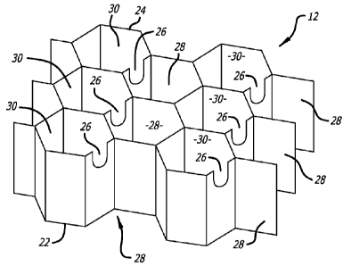
1000241 As shown in the FIGS. 1-3, the honeycomb 12 includes a first edge 22
that is located
closest to the noise source 18 and a second edge 24 that is located away from
the noise source
18. As a feature of the present invention, the honeycomb 12 includes cells 28
and 30 that are
coupled together by way of an acoustic pathway 26 to form pairs of
acoustically-coupled cells.
The individual pairs of cells 28 and 30 share a common wall in which the
acoustic pathway 26 is
formed. Each cell 28 may be viewed as a first acoustic cell that is defined by
the honeycomb
walls that extend between the first and second edges 22 and 24. Each cell 30
may be viewed as a
second acoustic cell that is also defined by the honeycomb walls that extend
between the first
and second edges 22 and 24. The solid face sheet 16 serves as a first acoustic
barrier 32 for the
first acoustic cells and a second acoustic barrier 34 for the second acoustic
cells.
1000251 Although it is preferred that the acoustic barriers 32 and 34 be
provided by a single
solid face sheet located along the second edge 24 of honeycomb 12, it is also
possible to form
the first and second acoustic barriers 32 and 34 with individual solid inserts
that are displaced
within the honeycomb cells away from the honeycomb cell edge. The positioning
of such
individual solid inserts must be such that the acoustic pathway 26 is located
between the first
edge of the honeycomb 22 and the first and second acoustic barriers 32 and 34.
1000261 The acoustic pathway can be located in the common cell wall at a
position spaced
away from the honeycomb second edge. However, it is preferred that the
acoustic pathway be
formed by arcuate shaped slots 26, as shown in FIG. 3, which seat against the
solid face sheet 16
to provide a closed arched shaped acoustic pathway. The acoustic pathway can
have a wide
-5-
CA 02868310 2019-09-23
WO 2014/021963 PCT/US2013/039458
variety of shapes provided that the opening in the common cell wall is
sufficiently large to allow
sound waves to travel through the pathway from the first acoustic cell 28 to
the second acoustic
cell 30. Arch shaped or other contoured openings of the type shown at 26 are
preferred since
they reduce the chance of fatigue cracking of the cell wall.
1000271 As a further feature of the invention, a third acoustic barrier 36 is
provided in the
second acoustic cells 30. The third acoustic barriers 36 may be located along
the first edge 22 of
the honeycomb. However, it is preferred that the third acoustic barriers 36 be
formed by
individual solid inserts that are displaced inward from the first edge 22 of
the honeycomb. The
displacement of the acoustic barrier 36 into the second acoustic cell 30
provides additional sound
dampening as will be discussed below.
1000281 FIGS. 4 and 5 are schematic representations of the acoustic dampening
properties that
are achieved when the first and second acoustic cells 28 and 30 are paired
together by way of an
acoustic pathway 26 in accordance with the present invention. As shown in FIG.
4, noise 20
enters the honeycomb through porous face sheet 14. The sound waves, as
represented by arrow
21, travel down through the first acoustic cell 28 until they reach the first
acoustic barrier 36
where they are directed laterally through the acoustic pathway 26. The second
acoustic barrier
34 prevents the sound waves from escaping so that they are directed back up
the second acoustic
cell 30 until they are stopped by the third acoustic barrier 36. The
acoustically coupled-cells
provide two noise attenuation zones or resonators that are capable of
dampening or impeding
noise having different wavelengths. The first noise attenuation zone is formed
by the first
acoustic cell 28 and that portion of the second acoustic cell 30 located below
the third acoustic
barrier 36. The effective acoustic or resonator length of the first noise
attenuation zone is (h +
h1). The second noise attenuation zone is formed by that portion of the second
acoustic cell 30
that is located between the third acoustic barrier 36 and the first edge of
the honeycomb. The
effective resonator length of the second attenuation zone is (h-h1).
1000291 Referring to FIG. 5, the two noise attenuation zones or resonators are
shown
schematically side-by-side where the first noise attenuation zone is shown at
38 and the second
noise attenuation zone is shown at 40. The acoustic coupling of the two cells
together forms one
resonator 38 that is substantially deeper than the other resonator 40.
Accordingly, instead of
having an acoustic structure where all cells are the same, the present
invention provides the
significant advantage of having one relatively long or deep acoustic resonator
that is capable of
-6-
CA 02868310 2019-09-23
WO 2014/021963 PCT/US2013/039458
dampening relatively low noise frequencies, while at the same time providing a
second resonator
that is capable of dampening noise frequencies that have a relatively higher
frequency.
1000301 Additional frequency dampening and attenuation can be provided by
including one or
more acoustic septums within one or both of the coupled acoustic cells. For
example, acoustic
septum 42 is included in the first acoustic cell 28 to provide an attenuator
with two degrees of
freedom. A second acoustic septum 44 may optionally be included in the second
acoustic cell
30 to provide an attenuator with three degrees of freedom.
1000311 The acoustic septum can be made from any of the standard acoustic
materials used it
to provide noise attenuation including woven fibers and perforated sheets. The
use of the woven
fiber acoustic septums is preferred. These acoustic materials are typically
provided as relatively
thin sheets of an open mesh fabric that are specifically designed to provide
noise attenuation. It
is preferred that the acoustic material be an open mesh fabric that is woven
from monofilament
fibers. The fibers may be composed of glass, carbon, ceramic or polymers.
Monofilament
polymer fibers made from polyamide, polyester, polyethylene
chlorotrifluoroethylene (ECTFE),
ethylene tetrafluoroethylene (ETFE), polytetrafluoroethyloene (PTFE),
polyphenylene sulfide
(PPS), polyfluoroethylene propylene (FEP), polyether ether ketone (PEEK),
polyamide 6 (Nylon
6, PA6) and polyamide 12 (Nylon 12, PA12) are just a few examples. Open mesh
fabric made
from PEEK is preferred for high temperature applications, such as nacelles for
jet engines.
Exemplary septums are described in United States Patents Nos. 7,434,659;
7,510,052 and
7,854,298. Septums made by laser drilling plastic sheets or films may also be
used.
1000321 There are a variety of ways in which adjoining acoustic cells can be
coupled together
to form the first and second noise attenuation zones. Some examples of
possible cell coupling
configurations are shown in FIGS. 6, 7 and 8. In these figures, cells that are
numbered 1
correspond to first acoustic cells 28 and cells that are numbered 2 correspond
to second acoustic
cells 30. The acoustic pathways connecting the two cells together are shown as
solid bars 3.
1000331 If desired, all of the cells of a given acoustic structure may be
acoustically coupled to
form acoustic pairs or acoustically coupled cell pairs can be dispersed among
non-acoustically
coupled cells. In some situations, it is desirable that only certain portions
of the acoustic
structure include acoustically coupled cell pairs. For example, in many
acoustic structures,
including nacelles, it is common practice to include openings in the honeycomb
cells that are
located in the lower portions of the structure in order to allow any
accumulated water to drain
from the structure. The drainage openings interconnect a large number of
honeycomb cells
-7-
CA 02868310 2019-09-23
WO 2014/021963 PCT/US2013/039458
together in order to ensure that adequate water drainage pathways are provided
to drain all of the
water from the structure. Use of such widely interconnected water drain
openings is inconsistent
with the present invention wherein the effective length of an acoustic cell is
increased by way of
coupling of two acoustic cells together.
1000341 The present invention has been described with respect to the acoustic
coupling of only
two adjacent cells together. If desired, three or more acoustic cells could be
acoustically linked
together using acoustic pathways and acoustic barriers in the same manner as
described above
with respect to the acoustic coupling of two cells. The linking of more than
two acoustic cells
together is warranted in those situations where the honeycomb is relatively
thin and/or a
relatively long resonator is required in order to dampen very low frequency
noise. The number
of the cells that are linked together would be determined by a combined
consideration of the
desired honeycomb thickness and the frequency range over which attenuation or
dampening is
desired.
1000351 The present invention has focused on the coupling of two cells
together because the
size and noise frequency requirements for dampening jet engine noise can be
met using nacelles
in which the honeycomb structure includes the coupling of two cells. For
example, the low-end
frequency range produced by large commercial jet engines is in the range of
500 to 2000 Hz. It
was found that honeycomb having a thickness of around 1 to 2 inches does not
have the
capability of dampening such low-frequency noise. However, by acoustically
coupling the cells
together, effective resonator lengths can be obtained that are able to
suppress such low-
frequency engine noise.
1000361 The materials used to make the honeycomb can be any of those typically
used in
acoustic structures including metals, ceramics and composite materials.
Exemplary metals
include aluminum and aluminum alloys. Exemplary composite materials include
fiberglass,
Nomex and various combinations of graphite or ceramic fibers with suitable
matrix resins.
Matrix resins that can withstand relatively high temperatures (300 F to 400 F)
are preferred.
The materials used to make the solid face sheet 16 can also be any of the
solid face sheet
materials commonly used for acoustic structures which typically include the
same type of
materials used to make the honeycomb structure. The materials used to make the
porous face
sheet 14 can also be any of the materials commonly used for such porous
structures provided
that the pores or perforations in the structure are sufficient to allow the
sound waves from the jet
engine or other source to enter into the acoustic cells or resonators.
-8-
CA 02868310 2019-09-23
WO 2014/021963 PCT/US2013/039458
1000371 In general, the honeycomb cells will typically have a cross-sectional
area ranging
from 0.05 square inch to 1 square inch or more. The depth of the cells
(honeycomb thickness or
core thickness) will generally range from 0.25 to 3 inches or more. For jet
engine nacelles, the
honeycomb cells will typically have a cross-sectional area of between about
0.1 to 0.5 square
inch and a depth of between about 1.0 and 2.0 inches. As an exemplary
advantage of the present
invention, nacelles having honeycomb cell depths at the lower end of the
thickness range (1.0
inch) can provide the same low-frequency noise attenuation or suppression that
is provided by
nacelles having thicknesses at the upper end of the thickness range (2.0
inch). For example, if
the first and second acoustic barriers 32 and 34 are located at the second
edge 24 of the
honeycomb and the third acoustic barrier 36 is placed 0.25 inch into the
second acoustic cell 30
of an acoustic pair of cells 28 and 30, the resulting effective length of the
acoustic cell pair is
1.75 inch and 0.25 inch.
1000381 The ability to take a nacelle that is a certain thickness and increase
the effective
resonator length up to two times and more is a significant advantage, since it
allows one to make
the nacelle as thin and lightweight as possible, while still being able to
dampen the relatively
lower frequency noise that is being generated by your jet engine designs. In
addition, the portion
40 of the second acoustic cell of the cell pair that is not used to extend the
effective acoustic
length of the first acoustic cell provides additional noise attenuation at a
different (higher)
frequency. This provides an increase in the range of frequencies (bandwidth)
that can be
effectively suppressed by the acoustic structure.
1000391 As mentioned previously, it is preferred that a solid face sheet 16 be
used to close off
the second edge of the honeycomb. In this situation, the first and second
sound barriers 32 and
34 are all located along the second edge of the honeycomb. In accordance with
the present
invention, it is possible to increase the bandwidth or range of frequencies
that can be suppressed
by simply varying the location of the third acoustic barrier 36 within the
second acoustic cell 30
of each acoustic pair 28 and 30. Even further increases in bandwidth
suppression can be
obtained by acoustically linking three or more cells together and combining
these acoustically
linked cells with the acoustically coupled cells at selected locations
throughout the acoustic
structure. Of course, it is also possible to provide acoustic structures which
include single
acoustic cells, acoustically coupled cell pairs and acoustically linked cell
triplets.
[000401 Further variations in noise attenuation can be achieved by varying the
size of the
acoustic pathway 26 between coupled acoustic cell pairs 28 and 30. The size of
the acoustic
-9-
CA 02868310 2014-09-23
WO 2014/021963 PCT/US2013/039458
pathway is chosen 'based on the effective length of the resonator (first noise
attenuation zone)
that results from the acoustic pathway between coupled cells and the frequency
of noise that is
being suppressed.
[000411 Having thus described exemplary embodiments of the present invention,
it should be
noted by those skilled in the art that the within disclosures are exemplary
only and that various
other alternatives, adaptations and modifications may be made within the scope
of the present
invention. Accordingly, the present invention is not limited by the above-
described
embodiments, but is only limited by the following claims.
-1.0-