Note: Descriptions are shown in the official language in which they were submitted.
CA 02868799 2014-09-24
WO 2013/154519
PCT/US2012/032697
COMPRESSIONAL VELOCITY CORRECTION
APPARATUS, METHODS, AND SYSTEMS
Background
[0001] Understanding the structure and properties of geological
formations can reduce the cost of drilling wells for oil and gas exploration.
Measurements made in a borehole (i.e., down hole measurements) are typically
performed to attain this understanding, to identify the composition and
distribution of material that surrounds the measurement device down hole.
[0002] For example, compressional wave velocity measurements can be
used to predict pore pressure in non-gas bearing formations, where the pore
pressure can be used to determine various characteristics of the formation.
However, the presence of gas and total organic carbon (TOC) in the formation
can affect measurement accuracy. Pore pressure prediction in these
circumstances (e.g., in shale gas formations) may be even more useful, because
the pressure can increase from a relatively normal to abnormally high values
over a comparatively short depth interval. Thus, pore pressure prediction in
shale gas plays may offer even greater challenges than in other types of
reservoirs.
Brief Description of the Drawings
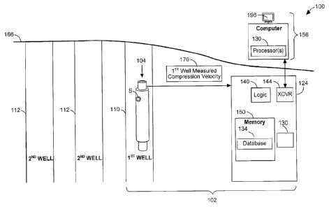
[0003] FIG. 1 is a block diagram of apparatus and systems according to
various embodiments of the invention.
[0004] FIG. 2 is a flow chart illustrating several methods
according to
various embodiments of the invention.
[0005] FIG. 3 illustrates a wireline system embodiment of the
invention.
[0006] FIG. 4 illustrates a drilling rig system embodiment of the
invention.
[0007] FIG. 5 is a flow chart illustrating several additional
methods
according to various embodiments of the invention.
[0008] FIG. 6 is a block diagram of an article according to various
embodiments of the invention.
CA 02868799 2014-09-24
WO 2013/154519
PCT/US2012/032697
[0009] FIG. 7 includes a graph illustrating the potential benefits
of
compressional velocity correction, according to various embodiments of the
invention.
Detailed Description
[0010] Since shear wave velocity measurement accuracy in a shale
gas
formation is often less affected than measurements of compressional wave
velocity, shear wave velocity measurements can sometimes be used to correct
directly corresponding compressional wave velocity measurement data.
However, the use of this correction mechanism may not be practical in the oil
and gas industry, because the measured shear wave velocity data that
corresponds directly to measured compressional wave velocity data in most
cases is not available. This is because the extra cost to measure shear wave
velocity data in shale gas formations can be prohibitive.
10011] To address some of these challenges, as well as others, apparatus,
systems, and methods are described herein that provide corrected compressional
velocity data to predict pore pressures, even when direct shear velocity wave
measurements in a target well are not available. In many embodiments,
corrected compressional velocity measurements in the target well can be
derived
from a statistical correlation between shear wave velocity and compressional
wave velocity information that is obtained from offset wells. In this way, the
accuracy of pore pressure prediction for a given target well (when no direct
shear
wave velocity measurement is available) may be significantly improved.
[0012] The statistical correlation of offset well data may be based
on data
obtained from shear wave and compressional wave offset well logs. Using
acquired offset well shear wave velocity data, a formula (hereinafter the
"Castagna formula") is used to determine corresponding corrected
compressional wave data in the offset well. Thus, the Castagna formula uses
only shear wave velocity data from the offset well to calculate a
corresponding
corrected compressional wave velocity data for the offset well.
[0013] The corrected compressional wave velocity data in the offset
well
is then compared to measured compressional wave velocity data in the offset
2
CA 02868799 2014-09-24
WO 2013/154519
PCT/US2012/032697
well, over depth, to derive a correlation equation. This equation can be used
to
determine a corrected compressional wave velocity in a target (e.g., pre-
drill)
well when compressional wave velocities have been measured in the target well.
Thus, corrected compressional wave velocities in the target well may be
obtained even when no measured shear wave velocity data exists for the well.
[0014] To provide a more consistent use of terminology throughout
this
document, several specific terms and phrases are used. They are defined as
follows:
* compressional wave velocities = velocities of compressional waves in a first
(e.g., target) well.
* measured compressional wave velocity data = a set of compressional wave
velocities measured in the first well.
* corrected compressional wave velocities (for the first well) = corrected
versions of the measured compressional wave velocity data in the first well.
* corrected compressional wave velocity data (for a second (e.g., offset)
well)
= a set of corrected compressional wave velocities for the second well,
derived
from original shear wave velocity data values in the second well.
* original compressional wave velocity data = a set of compressional wave
velocities measured in the second well, to be correlated with the corrected
compressional wave velocity data for the second well.
* original shear wave velocity data = a set of shear wave velocities
measured
in the second well.
[0015] Similarly, in the interest of consistency, several variables are
used
throughout this document. They are defined as follows:
* DTC original = measured compressional wave velocity data in sec/ ft
* DTS original = measured shear wave velocity data in Asec/ft
* DTCc = corrected compressional wave velocity data in Asec/ft
* Vp = 1/DTC original
* Vs = 1/DTS original
3
CA 02868799 2014-09-24
WO 2013/154519
PCT/US2012/032697
* DeltaTs = DTS original
* DeltaTp = DTC original
* DeltaTpc = DTCc
* Vpc = 1/DTCc
* PP dt Miller = pore pressure predicted with the Miller method, using
measured (uncorrected) compressional wave velocity data; those of ordinary
skill in the art are familiar with how to predict pore pressure using this
method.
Others that desire to learn more about using the Miller method are encouraged
to
consult the article "Casing Ultradeep, Ultralong Salt Sections in Deep Water:
A
Case Study for Failure Diagnosis and Risk Mitigation in Record-Depth Well",
Jincai Zhang, et al., SPE Annual Technical Conference and Exhibition, Denver,
Colorado, 2008; which is incorporated herein by reference in its entirety.
* PP dt Miller DT corrected = pore pressure predicted with the Miller
method,
using corrected compressional wave velocity data
[0016] A more detailed description of the mechanism used in some
embodiments will now be provided.
[0017] In one or more second (e.g., offset) wells, values for DTS
original
and DTC original are measured. The Castagna formula, well-known to those of
ordinary skill in the art, is used to take measured shear wave velocity data
(DTS
original), to determine corrected compressional wave velocity data for the
second well(s) (DTCc). Those that are interested in learning more about
various
uses for the Castagna formula may consult the article "Relationships Between
Compressional-Wave and Shear-Wave Velocities in Clastic Silicate Rocks", J.
P. Castagna et al. Geophysics, VOL. 50, NO. 4 (April 1985); P. 571-581.
[0018] One form of the Castagna formula that is used to calculate
DTCc
is shown as equation (1) below:
DTCc=1/(1.16/DTS+0.00446119) (DTCc and DTS are in kis/ft) (1)
[0019] The corrected compressional wave velocity data from the
second
well(s) (i.e., DTCc), and measured compressional wave velocity data from the
4
CA 02868799 2014-09-24
WO 2013/154519
PCT/US2012/032697
second well(s) (i.e., DTC original) are used to derive a correlation equation,
perhaps using a cross-plot of DTCc and DTC. The correlation equation, which
relates the corrected compressional wave velocity to the measured
compressional
wave velocity, both in the second well, may take the form of equation (2)
below:
corrected compressional wave velocity (second well) ¨ slope measured
compressional wave velocity (second well) + intercept (2)
[0020] This equation can then be used with measured compressional
wave velocity data in the first well (e.g., a target well), when measured
shear
wave velocity data is absent. Equation (2) may take a linear form, as shown,
or
an exponential one, in some embodiments. Those of ordinary skill in the art,
after studying this disclosure, will realize that many forms of equation (2)
may
be used, depending on how well the data fits the form of the equation.
[0021] For example, if the correlation between the measured and
corrected compressional wave velocity data in the second well appears to be a
substantially linear one, as shown above, the measured compressional wave data
from the first well can be substituted into the correlation equation (2) to
calculate
corrected compressional wave velocity data for the first well. This is shown
in
equation (3) below:
corrected compressional wave velocity (first well) = slope * measured
compressional wave velocity (first well) + intercept (3)
[0022] The corrected compressional wave data determined for the first
well can then be used to calculate pore pressure (e.g., using the Miller
Method),
in the first well, as an improved estimate of the pressure (when compared to
the
use of uncorrected compressional wave velocity data). Various embodiments
that include some or all of these features will now be described in detail.
[0023] FIG. 1 is a block diagram of apparatus 102 and systems 100
according to various embodiments of the invention. In some embodiments, a
system 100 includes a housing 104. The housing 104 might take the form of a
5
CA 02868799 2014-09-24
WO 2013/154519
PCT/US2012/032697
wireline tool body, or a down hole tool. Processor(s) 130 within the system
100
may be located at the surface 166, as part of a surface logging facility 156,
or in
a data acquisition system 124, which may be above or below the Earth's surface
166 (e.g., attached to the housing 104).
[0024] A system 100 may further comprise a data transceiver 144 (e.g., a
telemetry transmitter and/or receiver) to transmit acquired data 170 (e.g.,
measured compressional wave velocity data) from sensors S to the surface
logging facility 156. Logic 140 can be used to acquire the data as signals,
according to the various methods described herein. Acquired data 170, as well
as other data, can be stored in the memory 150, perhaps as part of a database
134.
[0025] In many embodiments, the data 170 corresponds solely to
compressional wave velocities measured in the first well (e.g., target well)
110.
That is, for most embodiments, it is assumed that measured values for shear
wave velocities in the first well 110 are inaccessible, or otherwise
unavailable.
[0026] Original compressional wave velocity data and original shear
wave velocity data may be determined by making measurements in second wells
(e.g., offset wells) 112, using sensors S, and then storing the data in the
memory
150, or elsewhere, for later use.
[0027] FIG. 2 is a flow chart illustrating several methods 211 according
to various embodiments of the invention. These methods 211 can be used to
correct measured compressional wave velocity data in a target well. The
methods 211 may be applied to a number of configurations of the system 100
shown in FIG. 1.
[0028] In some embodiments, a method 211 may begin at block 221, and
continue on to block 225, to determine whether shear wave velocity
measurements have been made in the target well, perhaps in the form of a shear
wave log trace (e.g., a trace of DeltaTs). If so, then the method 211 may
continue on to block 229 with calculating corrected values of Vp using the
Castagna formula (i.e., Vpc in km/sec = 1.16Vs + 1.36). In this case, Vs may
be
determined using a log trace of DeltaTs (since Vs in ft/sec = 106/(DeltaTs in
1.ts/ft)) from the target well.
6
CA 02868799 2014-09-24
WO 2013/154519
PCT/US2012/032697
[0029] The method 211 may continue on to block 233, to use the
values
of Vpc to construct a correction algorithm that provides DeltaTpc as the end
result. Vp may be obtained using a log trace of DeltaTp from the target well
(since Vp = 1/DTC original, and DeltaTp = DTC original, which means that Vp
in ft/sec = 106/(DeltaTp in us/ft)). As noted previously, DeltaTpc, the end
result,
can also be expressed as DTCc = 1/Vpc.
[0030] At this point, the method 211 continues on to block 237,
where
DeltaTpc is used as the input to a pore pressure prediction algorithm (e.g.,
the
Miller method, among others) to provide predicted pore pressure in the target
well. The method 211 may then end at block 245.
[0031] In some embodiments, after the method 211 begins at block
221,
the determination is made at block 225 that shear wave velocity measurements
have not been made in the target well, or are otherwise not available. In this
case, the method 211 may continue on to block 241, to empirically derive a
con-elation from offset well data, as described above. This correlation
permits
calculating DeltaTpc for the target well, even in the absence of measured
shear
wave velocity data for the target well.
[0032] For example, a spreadsheet table of measured shear wave
velocity
(DTS original) and measured compressional wave velocity (DTC original) in
one or more offset wells may be constructed. Corrected compressional wave
values (DTCc) for each offset well may be determined using the Castagna
formula. A basic spreadsheet linear function may then be used to build a
regression analysis for DTCc and DTC.
[0033] At this point, the average slope and intercept among the
offset
wells can be used to develop a linear equation (if that is the desired form of
the
correlation equation), as shown in equation (4) below:
DTCc = Average_Slope*DTC + Average_Intercept (4)
[0034] For nearby target wells which don't have measured values of
DTS original, but do have measured DTC original values, the DTC original
values can be entered into equation (4) to calculate DTCc for each target
well.
7
CA 02868799 2014-09-24
WO 2013/154519
PCT/US2012/032697
These values of DTCc can be used to predict pore pressure for shale gas
formations in the same region.
[0035] Thus, referring now to FIGs. 1-2, it can be seen that many
embodiments may be realized, including a system 100 that comprises a housing
104 and one or more processors 130, which may be located down hole or at the
surface. For example, in some embodiments a system 100 comprises a housing
104 to be operated in a first well 110 and a processor 130 to receive measured
compressional wave velocity data 170 associated with the first well 130. The
processor 130 may be configured to determine corrected compressional wave
velocities for the first well 110 using a combination of the measured
compressional wave velocity data 170 and corrected compressional wave
velocity data associated with one or more second wells 112 different from the
first well 110. The processor 130 may also be configured to generate predicted
pore pressure data for the first well 110, using the corrected compressional
wave
velocities (for the first well 110).
[0036] An acoustic sensor (e.g., transducer) may be used to receive
acoustic signals, after they have interacted with the formation surrounding
the
housing 104. Thus, the system 100 may comprise a sensor S, such as an acoustic
sensor, attached to the housing 104. The sensor S can be used to receive
acoustic signals associated with the measured compressional wave velocity
data.
[0037] A telemetry transmitter can be used to transmit the measured
acoustic data to the surface. Thus, the system 100 may comprise a transceiver
144, including a telemetry transmitter, attached to the housing. The telemetry
transmitter may be used to communicate data associated with the acoustic
signals as the measured compressional wave velocity data 170 to a surface data
processing facility 156. The housing 104 may comprise a wireline tool or a
down hole tool, such as a logging while drilling tool or a measurement while
drilling tool, among others.
[0038] In the system 100, the processor 130 may be housed by the
housing 104, or a surface data processing facility 156, or both, depending on
where various calculations are to be made. Thus, processing during various
activities conducted by the system 100 may be conducted both down hole and at
8
CA 02868799 2014-09-24
WO 2013/154519
PCT/US2012/032697
the surface 166. In this case, the processor 130 may comprise multiple
computational units, some located down hole, and some at the surface 166.
Additional embodiments may be realized, and thus, some additional examples of
systems will now be described.
[0039] FIG. 3 illustrates a wireline system 364 embodiment of the
invention, and FIG. 4 illustrates a drilling rig system 464 embodiment of the
invention. Therefore, the systems 364, 464 may comprise portions of a wireline
logging tool body 370 as part of a wireline logging operation, or of a down
hole
tool 424 as part of a down hole drilling operation. The systems 364 and 464
may comprise any one or more elements of the system 100 shown in FIG. 1.
[0040] Thus, FIG. 3 shows a well during wireline logging
operations. In
this case, a drilling platform 386 is equipped with a derrick 388 that
supports a
hoist 390.
100411 Drilling oil and gas wells is commonly carried out using a
string
of drill pipes connected together so as to form a drilling string that is
lowered
through a rotary table 310 into a wellbore or borehole 312. Here it is assumed
that the drilling string has been temporarily removed from the borehole 312 to
allow a wireline logging tool body 370, such as a probe or sonde, to be
lowered
by wireline or logging cable 374 into the borehole 312. Typically, the
wireline
logging tool body 370 is lowered to the bottom of the region of interest and
subsequently pulled upward at a substantially constant speed.
[0042] During the upward trip, at a series of depths, various
instruments
included in the tool body 370 may be used to perform measurements (e.g., made
by portions of the apparatus 102 shown in FIG. 1) on the subsurface geological
formations 314 adjacent the borehole 312 (and the tool body 370). The borehole
312 may represent one or more offset wells, or a target well.
[0043] The measurement data can be communicated to a surface
logging
facility 392 for processing, analysis, and/or storage. The logging facility
392
may be provided with electronic equipment for various types of signal
processing, which may be implemented by any one or more of the components
of the apparatus 102 or system 100 in FIG. 1. Similar formation evaluation
data
9
CA 02868799 2014-09-24
WO 2013/154519
PCT/US2012/032697
may be gathered and analyzed during drilling operations (e.g., during logging
while drilling operations, and by extension, sampling while drilling).
[0044] In some embodiments, the tool body 370 is suspended in the
wellbore by a wireline cable 374 that connects the tool to a surface control
unit
(e.g., comprising a workstation 354). The tool may be deployed in the borehole
312 on coiled tubing, jointed drill pipe, hard wired drill pipe, or any other
suitable deployment technique.
[0045] Turning now to FIG. 4, it can be seen how a system 464 may
also
form a portion of a drilling rig 402 located at the surface 404 of a well 406.
The
drilling rig 402 may provide support for a drill string 408. The drill string
408
may operate to penetrate the rotary table 310 for drilling the borehole 312
through the subsurface formations 314. The drill string 408 may include a
Kelly
416, drill pipe 418, and a bottom hole assembly 420, perhaps located at the
lower
portion of the drill pipe 418.
[0046] The bottom hole assembly 420 may include drill collars 422, a
down hole tool 424, and a drill bit 426. The drill bit 426 may operate to
create
the borehole 312 by penetrating the surface 404 and the subsurface fonuations
314. The down hole tool 424 may comprise any of a number of different types
of tools including measurement while drilling tools, logging while drilling
tools,
and others.
[0047] During drilling operations, the drill string 408 (perhaps
including
the Kelly 416, the drill pipe 418, and the bottom hole assembly 420) may be
rotated by the rotary table 310. Although not shown, in addition to, or
alternatively, the bottom hole assembly 420 may also be rotated by a motor
(e.g.,
a mud motor) that is located down hole. The drill collars 422 may be used to
add weight to the drill bit 426. The drill collars 422 may also operate to
stiffen
the bottom hole assembly 420, allowing the bottom hole assembly 420 to
transfer the added weight to the drill bit 426, and in turn, to assist the
drill bit
426 in penetrating the surface 404 and subsurface formations 314.
[0048] During drilling operations, a mud pump 432 may pump drilling
fluid (sometimes known by those of ordinary skill in the art as "drilling
mud")
from a mud pit 434 through a hose 436 into the drill pipe 418 and down to the
CA 02868799 2014-09-24
WO 2013/154519
PCT/US2012/032697
drill bit 426. The drilling fluid can flow out from the drill bit 426 and be
returned to the surface 404 through an annular area between the drill pipe 418
and the sides of the borehole 312. The drilling fluid may then be returned to
the
mud pit 434, where such fluid is filtered. In some embodiments, the drilling
fluid can be used to cool the drill bit 426, as well as to provide lubrication
for the
drill bit 426 during drilling operations. Additionally, the drilling fluid may
be
used to remove subsurface formation cuttings created by operating the drill
bit
426.
[0049] Thus, referring now to FIGs. 1 and 3-4, it may be seen that
in
some embodiments, the systems 364, 464 may include a drill collar 422, a down
hole tool 424, and/or a wireline logging tool body 370 to house one or more
apparatus 102, similar to or identical to the apparatus 102 described above
and
illustrated in FIG. 1. Any and all components of the system 100 in FIG. 1 may
also be housed by the tool 424 or the tool body 370.
[0050] Thus, for the purposes of this document, the term "housing" may
include any one or more of a drill collar 422, a down hole tool 424, or a
wireline
logging tool body 370 (all having an outer surface, to enclose or attach to
magnetometers, sensors, fluid sampling devices, pressure measurement devices,
temperature measurement devices, transmitters, receivers, acquisition and
processing logic, and data acquisition systems). The tool 424 may comprise a
down hole tool, such as an LWD tool or MWD tool. The wireline tool body 370
may comprise a wireline logging tool, including a probe or sonde, for example,
coupled to a logging cable 374. Many embodiments may thus be realized.
[0051] For example, in some embodiments, a system 364, 464 may
include a display 396 to present compressional wave velocity data in a target
well, both measured and corrected, as well as database information (e.g.,
measured values of shear and compressional wave velocity data in offset
wells),
perhaps in graphic form. Predicted pore pressure information, using
uncorrected
and/or corrected compressional wave velocity data in the target well, may also
be displayed.
[0052] The systems 100, 364, 464; apparatus 102; housing 104; data
acquisition system 124; processors 130; database 134; logic 140; transceiver
11
CA 02868799 2014-09-24
WO 2013/154519
PCT/US2012/032697
144; memory 150; surface logging facility 156; surface 166; data 170; rotary
table 310; borehole 312; computer workstations 354; wireline logging tool body
370; logging cable 374; drilling platform 386; derrick 388; hoist 390; logging
facility 392; display 396; drill string 408; Kelly 416; drill pipe 418; bottom
hole
assembly 420; drill collars 422; down hole tool 424; drill bit 426; mud pump
432; mud pit 434; hose 436; and sensors S may all be characterized as
"modules" herein.
[0053] Such modules may include hardware circuitry, and/or a
processor
and/or memory circuits, software program modules and objects, and/or
firmware, and combinations thereof, as desired by the architect of the
apparatus
102 and systems 100, 364, 464 and as appropriate for particular
implementations
of various embodiments. For example, in some embodiments, such modules
may be included in an apparatus and/or system operation simulation package,
such as a software electrical signal simulation package, a power usage and
distribution simulation package, a power/heat dissipation simulation package,
and/or a combination of software and hardware used to simulate the operation
of
various potential embodiments.
[0054] It should also be understood that the apparatus and systems
of
various embodiments can be used in applications other than for logging
operations, and thus, various embodiments are not to be so limited. The
illustrations of apparatus 102 and systems 100, 364, 464 are intended to
provide
a general understanding of the structure of various embodiments, and they are
not intended to serve as a complete description of all the elements and
features
of apparatus and systems that might make use of the structures described
herein.
[0055] Applications that may include the novel apparatus and systems of
various embodiments include electronic circuitry used in high-speed computers,
communication and signal processing circuitry, modems, processor modules,
embedded processors, data switches, and application-specific modules. Such
apparatus and systems may further be included as sub-components within a
variety of electronic systems, such as televisions, cellular telephones,
personal
computers, workstations, radios, video players, vehicles, signal processing
for
12
CA 02868799 2014-09-24
WO 2013/154519
PCT/US2012/032697
geothermal tools and smart transducer interface node telemetry systems, among
others. Some embodiments include a number of methods.
[0056] For example, FIG. 5 is a flow chart illustrating several
additional
methods 511 according to various embodiments of the invention. The method
511 may comprise processor-implemented methods, to execute on one or more
processors that perform the methods.
[0057] One embodiment of the methods 511 may begin at block 521
with acquiring original second well (e.g., offset well) data from a remote
location. This data can be provided directly, via measurement, or indirectly,
via
storage. Thus, the activity at block 521 may comprise receiving original
compressional wave velocity data and original shear wave velocity data
associated with one or more second wells. The second wells may be located in
the same shale base formation region as a first well (e.g., a target well) for
which
compressional wave velocity data will be corrected (when no measured shear
wave velocity data for the first well is available).
[0058] The method 511 may continue on to block 525 with measuring
compressional wave velocities in a geological formation surrounding the first
well, to provide measured compressional wave velocity data. Acoustic signal
data can be acquired to provide the measured compressional wave velocity data.
Thus, the activity at block 525 may comprise receiving acoustic signals in the
first well from the geological formation, and determining the measured
compressional wave velocity data using the compressional wave velocities
associated with the acoustic signals.
[0059] The measured compressional wave velocity data may be
transmitted to the surface, perhaps for additional processing. Thus, the
method
511 may continue on to block 529, to include transmitting the measured
compressional wave velocity data to a surface computer in some embodiments.
[0060] The method 511 may continue on to block 533 to determine
whether acquisition of the first well measurements is complete. If not, the
method 511 may return to block 525 to acquire additional data. If so, then the
method 511 may continue on to block 537.
13
CA 02868799 2014-09-24
WO 2013/154519
PCT/US2012/032697
[0061] At block 537, the method 511 may include determining
corrected
compressional wave velocities for the first well using a combination of the
measured compressional wave velocity data and corrected compressional wave
velocity data associated with one or more second wells different from the
first
well.
[0062] As noted previously, the original shear wave velocity data
from
the second well can be used to determine corrected compressional wave velocity
data for the second well. Thus, the activity at block 537 may comprise
determining the corrected compressional wave velocity data associated with the
one or more second wells, using the original shear wave velocity data
associated
with those wells.
[0063] The corrected compressional wave velocity in the second well
can
be correlated with the original compressional wave velocity data, over depth,
in
the second well. Thus, the activity at block 537 may comprise correlating the
corrected compressional wave velocity data associated with the one or more
second wells with the original compressional wave velocity data (from the one
or more second wells) over a depth domain, to provide a correlation.
[0064] As noted previously, an equation that defines a correction
formula
for the measured compressional wave velocity data in the first well can be
developed, using the correlation between the original and corrected
compressional wave data for the second well. The equation may take a linear
form, an exponential form, or some other form. Thus, the activity at block 537
may comprise determining an equation defined by the correlation, the equation
describing a relationship between the measured compressional wave velocity
data for the first well, and the corrected compressional wave velocities for
the
first well.
[0065] The equation that defines a correction formula for the
measured
compressional wave velocity data in the first well can sometimes be improved
by using a correlation relationship between the original (measured)
compressional wave velocity data, and corrected compressional wave velocity
data, for multiple second wells. For example, this relationship may comprise
an
averaged correlation. Thus, the activity at block 537 may comprise determining
14
CA 02868799 2014-09-24
WO 2013/154519
PCT/US2012/032697
an average slope and an average intercept of a substantially linear
relationship
between the corrected compressional wave velocities of the first well and the
measured compressional wave velocity data for the first well. The average
slope
and the average intercept may in turn be determined by a relationship between
the original compressional wave velocity data and corrected compressional wave
velocity data, based on the original shear wave velocity data, associated with
multiple second wells.
[0066] The original, measured, and corrected data, including
corrected
compressional wave velocities, can be entered into a table. Thus, the method
511 may continue on to block 541 to include storing the corrected
compressional
wave velocities, among other data, in a table.
[0067] The method 511 may continue on to block 545 to include
generating predicted pore pressure data for the first well, using the con-
ected
compressional wave velocities.
[0068] The predicted pore pressure data can be "published", which for
the purposes of this document means any one or more of: stored in a memory,
shown on a display, or printed on paper. Thus, the method 51 1 may continue on
to block 549 to include publishing the predicted pore pressure data on a
display.
[0069] Other aspects of down hole operations that can be predicted
from
the predicted pore pressure data can also be published. Thus, for example, the
activity at block 549 may include publishing predicted seal failure or well
bore
failure based on the predicted pore pressure
[0070] Predicted pore pressure data can be used as the basis for
adjusting
the mud weight down hole, during drilling operations. Thus, in some
embodiments, the method 511 may continue on to block 553 to include adjusting
mud weight to balance pore pressure in the geological formation, based on the
predicted pore pressure data.
[0071] It should be noted that the methods described herein do not
have
to be executed in the order described, or in any particular order. Moreover,
various activities described with respect to the methods identified herein can
be
executed in iterative, serial, or parallel fashion. The various elements of
each
method (e.g., the methods shown in FIGs. 2 and 5) can be substituted, one for
CA 02868799 2014-09-24
WO 2013/154519
PCT/US2012/032697
another, within and between methods. Information, including parameters,
commands, operands, and other data, can be sent and received in the form of
one
or more carrier waves.
[0072] Upon reading and comprehending the content of this
disclosure,
one of ordinary skill in the art will understand the manner in which a
software
program can be launched from a computer-readable medium in a computer-
based system to execute the functions defined in the software program. One of
ordinary skill in the art will further understand the various programming
languages that may be employed to create one or more software programs
designed to implement and perform the methods disclosed herein. For example,
the programs may be structured in an object-orientated format using an object-
oriented language such as Java or C#. In another example, the programs can be
structured in a procedure-orientated format using a procedural language, such
as
assembly or C. The software components may communicate using any of a
number of mechanisms well known to those skilled in the art, such as
application
program interfaces or interprocess communication techniques, including remote
procedure calls. The teachings of various embodiments are not limited to any
particular programming language or environment. Thus, other embodiments
may be realized.
[0073] For example, FIG. 6 is a block diagram of an article 600 of
manufacture according to various embodiments, such as a computer, a memory
system, a magnetic or optical disk, or some other storage device. The article
600
may include one or more processors 616 coupled to a machine-accessible
medium such as a memory 636 (e.g., removable storage media, as well as any
tangible, non-transitory memory including an electrical, optical, or
electromagnetic conductor having associated information 638 (e.g., computer
program instructions and/or data), which when executed by one or more of the
processors 616, results in a machine (e.g., the article 600) performing any of
the
actions described with respect to the methods of FIGs. 2 and 5, and the
systems
of FIGs. 1, 3, and 4. The processors 616 may comprise one or more processors
sold by Intel Corporation (e.g., Intel CoreTM processor family), Advanced
16
CA 02868799 2014-09-24
WO 2013/154519
PCT/US2012/032697
Micro Devices (e.g., AMD AthlonTM processors), and other semiconductor
manufacturers.
[0074] In some embodiments, the article 600 may comprise one or
more
processors 616 coupled to a display 618 to display data processed by the
processor 616 and/or a wireless transceiver 620 (e.g., a down hole telemetry
transceiver) to receive and transmit data processed by the processor.
[0075] The memory system(s) included in the article 600 may include
memory 636 comprising volatile memory (e.g., dynamic random access
memory) and/or non-volatile memory. The memory 636 may be used to store
data 640 processed by the processor 616, including corrected compressional
wave velocity data that is associated with a first (e.g., target) well, where
no
measured shear wave velocity data is available.
[0076] In various embodiments, the article 600 may comprise
communication apparatus 622, which may in turn include amplifiers 626 (e.g.,
preamplifiers or power amplifiers) and one or more transducers 624 (e.g.,
transmitting and/or receiving devices, such as acoustic transducers). Signals
642
received or transmitted by the communication apparatus 622 may be processed
according to the methods described herein.
[0077] Many variations of the article 600 are possible. For
example, in
various embodiments, the article 600 may comprise a down hole tool, including
any one or more elements of the system 100 shown in FIG. 1. Some of the
potential advantages of implementing the various embodiments described herein
will now be described.
[0078] FIG. 7 includes a graph 711 illustrating the potential
benefits of
compressional velocity correction, according to various embodiments of the
invention. The graph 711 is used as an example to show how various
embodiments may provide a more accurate pore pressure estimate than
conventional mechanisms.
[0079] First, consider data indicating values of the original
compressional interval travel time over depth, as shown for an actual well in
graph 715. The corresponding calculated pore pressure (using the Miller
method) is shown as an uncorrected, predicted pore pressure 721 in graph 711.
17
CA 02868799 2014-09-24
WO 2013/154519
PCT/US2012/032697
[0080] Second, consider data indicating values of the corrected
compressional interval travel time over depth, as shown in graph 719. The
corresponding calculated pore pressure (using the Miller method) is shown as a
corrected, predicted pore pressure 725 in graph 711.
[0081] As can be seen in the graph 711, the magnitude of the predicted
pore pressure 725 is reasonable over the shallow section of the well (e.g.,
from
about 6400 to 8900ft). These values also provide a good match to kicks data
729
(i.e., the square marks in the graph 711, illustrating entry of water, gas,
oil, or
other formation fluid into the wellbore) in the deep section of the well.
[0082] However, the predicted pore pressure 721 that is obtained from
using uncorrected Vp data (or sonic compressional transit time taken directly
a
well log) does not give the same result. For example, the predicted pore
pressure
721 in the shallow section of the well is far below the normal pore pressure
of
about 8.5ppg. Indeed, the pore pressure in the shallow section should be
around
this normal value, or even mildly over-pressured, based on measured pressure
from nearby offset wells (e.g., Bossier and Haynesville shales). Thus, the
predicted pore pressure 725 comprises a superior result. when compared to the
predicted pore pressure 721 that is based on uncorrected data.
[0083] In summary, the apparatus, systems, and methods disclosed
herein, using offset well shear wave velocity data to provide a basis for
offset
well compressional wave velocity correlation, may provide increased accuracy
with respect to correcting the measured compressional wave velocity in a
target
well ¨ when no directly measured shear wave velocity data is available. The
ability to predict pore pressure using only acquired compressional wave
velocity
data, when directly-measured shear wave velocity data is absent, may also be
more efficient, because it can extend the scope of pore pressure analysis,
particularly for unconventional plays. The mechanisms described herein can
also be used to solve the technical problem of accurately predicting pore
pressure in shale gas formations. As a result, the value of these services
provided by an operation/exploration company may be significantly enhanced.
100841 The accompanying drawings that form a part hereof, show by
way of illustration, and not of limitation, specific embodiments in which the
18
CA 02868799 2014-09-24
WO 2013/154519
PCT/US2012/032697
subject matter may be practiced. The embodiments illustrated are described in
sufficient detail to enable those skilled in the art to practice the teachings
disclosed herein. Other embodiments may be utilized and derived therefrom,
such that structural and logical substitutions and changes may be made without
departing from the scope of this disclosure. This Detailed Description,
therefore,
is not to be taken in a limiting sense, and the scope of various embodiments
is
defined only by the appended claims, along with the full range of equivalents
to
which such claims are entitled.
[0085] Such embodiments of the inventive subject matter may be
referred to herein, individually and/or collectively, by the term "invention"
merely for convenience and without intending to voluntarily limit the scope of
this application to any single invention or inventive concept if more than one
is
in fact disclosed. Thus, although specific embodiments have been illustrated
and
described herein, it should be appreciated that any arrangement calculated to
achieve the same purpose may be substituted for the specific embodiments
shown. This disclosure is intended to cover any and all adaptations or
variations
of various embodiments. Combinations of the above embodiments, and other
embodiments not specifically described herein, will be apparent to those of
skill
in the art upon reviewing the above description.
10086] The Abstract of the Disclosure is provided to comply with 37
C.F.R. 1.72(b), requiring an abstract that will allow the reader to quickly
ascertain the nature of the technical disclosure. It is submitted with the
understanding that it will not be used to interpret or limit the scope or
meaning
of the claims. In addition, in the foregoing Detailed Description, it can be
seen
that various features are grouped together in a single embodiment for the
purpose of streamlining the disclosure. This method of disclosure is not to be
interpreted as reflecting an intention that the claimed embodiments require
more
features than are expressly recited in each claim. Rather, as the following
claims
reflect, inventive subject matter lies in less than all features of a single
disclosed
embodiment. Thus the following claims are hereby incorporated into the
Detailed Description, with each claim standing on its own as a separate
embodiment.
19