Note: Descriptions are shown in the official language in which they were submitted.
CA 02868839 2014-09-29
WO 2014/029407
PCT/EP2012/003558
- 1 -
Corneal tissue detection and monitoring device
In eye surgery, such as LASIK surgery, information may be gathered for use in
the
surgery. For example, the shape or thickness of the corneal tissue before
surgery or
the depth of cuts made during surgery may be measured. As another example,
images of any scars within the corneal tissue due to previous surgeries may be
taken.
As shown in Fig. 3, the human cornea has five layers. The outer layer is the
epithelium 64, a thin tissue layer of fast-growing and easily regenerated
cells,
typically composed of about six layers of cells. Next is the Bowman's layer
62, which
is an 8-14pm thick condensed layer of collagen that protects the stroma. The
stroma
60 is a thick, transparent middle layer that includes regularly arranged
collagen fibers
(also called "fibrils") and sparsely distributed interconnected keratocytes,
which are
cells responsible for general repair and maintenance. The Descemet's membrane
66
is an approximately 5-20pm thick acellular layer. Finally, the endothelium 68
is an
approximately 5pm thick layer of mitochondria-rich cells.
The stroma 60 is the thickest layer of the cornea, accounting for up to 90% of
the
corneal thickness. The stroma is composed of about 200 plates of collagen
fibrils
called "lamellae", superimposed on one another. Each lamella is about 1.5-2.5
pm
thick. The fibres of each lamella are parallel to one another, but generally
at right
angles to the fibers of adjacent lamellae. Fibres frequently interweave
between
adjacent layers. A remodelling, or reshaping, of the stroma during surgery
alters the
light-focussing capability of the cornea, which may correct a patient's
vision.
A prevalent type of surgery for reshaping the cornea is LASIK (laser-assisted
in situ
keratomileusis) surgery, which is performed using a laser. LASIK surgery is
typically
performed in three steps. A first step creates a flap of corneal tissue. A
second step
remodels the cornea underneath the flap with a laser. In a third step, the
flap is
repositioned.
Before performing LASIK surgery, the thickness of the cornea is typically
measured
using at least one corneal pachymetry technique. During surgery, cutting of
the
corneal tissue as well as reshaping of the stroma layer may be monitored. It
is
typically desirable that the Descemet's membrane and endothelium remain
unharmed
CA 02868839 2014-09-29
WO 2014/029407
PCT/EP2012/003558
- 2 -
while the flap is cut and the cornea is reshaped. Known diagnostic systems,
however,
have limited accuracy and image resolution and are difficult to integrate with
the
therapeutic systems used in LASIK surgery.
Known diagnostic devices for pre-operative and intra-operative diagnosis of
corneal
tissue include Scheimpflug cameras and Optical Coherence Tomography (OCT)
scanners. Scheimpflug cameras used in corneal pachymetry have an image
resolution
limited to about lOpm. Scheimpflug cameras can be used to detect the position
of
the outer surfaces of the cornea, but do not provide information about the
inner
structure of the cornea.
Optical coherence tomography is an interferometric technique that is used to
capture
three-dimensional images from within optical scattering media, such as
biological
tissue. For applications in corneal pachymetry, OCT scanners have a resolution
of
about 5-10pm, which can be increased to approximately 1-2pm with known
technologies. Wavelengths used for detection are typically in the range of 800-
1300nm.
OCT scanners generate signals by detecting significant differences in the
refractive
indexes of adjacent tissues. The different refractive indexes of the adjacent
tissues
cause phase shifts in reflected, or back-scattered, light. However, tissue
structures
on a sub-micrometer scale and tissue boundaries that are not distinguished by
a
large difference in refractive index are not detectable. For example, the
position and
structure of the collagen fibrils of the stroma and the layered structure of
the human
cornea are not detectable using OCT scanning.
Scheimpflug cameras and OCT scanners use wavelengths that overlap the range of
wavelengths used by surgical microscopes, e.g., in the visual range of 420 nm
to
700nm. Therefore, using these detection devices intra-operatively can yield
interference between the systems, leading to decreased measurement accuracy
and/or compromised image quality.
Providing a separate diagnostic device, in addition to the therapeutic device,
such as
a femtosecond-pulse laser, increases the total cost of equipment needed to
perform
the surgery.
It is therefore an object of examples of the invention to provide an eye-
surgical laser
apparatus, the use of the eye-surgical laser apparatus, and a method of
scanning a
CA 02868839 2016-02-05
3
corneal tissue of an eye that improve on existing apparatuses, uses and
methods
by enhancing measurement accuracy and/or use during surgery.
According to a first aspect of the invention, an eye-surgical laser apparatus
is
provided. The apparatus comprises optics that are adapted to focus a laser
beam
having a wavelength and a pulse length at a focus within a corneal tissue of
an eye.
Furthermore, the apparatus comprises a detection element adapted to detect, as
an
image-producing signal, light that is formed, at the focus, as a frequency
multiple
and backscattered to produce image information about the inner corneal tissue.
The detection of backscattered light at a frequency multiple allows high-
resolution
images to be captured, as the light at a frequency multiple has a shorter
wavelength, and consequently provides an improved image resolution.
In one embodiment of the first aspect, the optics may be adapted to
successively
focus the laser beam at a further focus, which may be located at a depth
different
from the depth of the previous focus. The detection element is adapted to
detect,
as a further image-producing signal, light that is formed, at said further
focus, as a
frequency multiple and backscattered or forward emitted, to produce said image
information about the inner corneal tissue. Collecting back-scattered light
from two
different focus depths enables the formation of a three-dimensional image by,
e.g.,
computationally combining the image signals from both depths.
In a further embodiment of the first aspect, the optics may be adapted to
successively focus the laser beam at a plurality of focuses at varying depths
within
the corneal tissue of the eye. The detection element can be adapted to detect,
as
image-producing signals, light that is formed, at each of said focuses, as a
frequency multiple and backscattered or forward emitted, to compile three-
dimensional image information about the inner corneal tissue. Collecting back-
scattered light from a plurality of focus depths enables the formation of
three-
CA 02868839 2016-08-31
4
dimensional images by, e.g., computationally combining the image signals at
the
plurality of depths.
A second aspect of the invention concerns the use of the eye-surgical laser
apparatus
described above for scanning inner corneal tissue of an eye. The apparatus
allows
for the detection of backscattered light at a frequency multiple, which may be
used
to produce high-resolution images of corneal tissue while minimizing
interference
with the operation microscope.
One embodiment of the second aspect concerns the use of an eye-surgical laser
apparatus described above for pre- or intra-operative diagnostic purposes. For
this
type of use, the wavelength of the laser beam is selected such that the beam
energy
in the focus of the laser beam is lower than an energy required for
photodisruption of
the corneal tissue.
A third aspect of the invention concerns a method of scanning a corneal tissue
of an
eye. A laser beam having a wavelength and a pulse length is focused at a focus
within a corneal tissue of an eye. A light that is formed, at the focus, as a
frequency
multiple and backscattered is detected as an image-producing signal, to
produce
image information about the inner corneal tissue.
Certain exemplary embodiments can provide an eye-surgical laser apparatus,
comprising: a laser source adapted to: create a laser beam with a variable
wavelength or variable pulse energy; set a wavelength or a pulse length or
both to
create the laser beam with a lower energy that does not cause photodisruption
in
corneal tissue; and set a wavelength or a pulse length or both to create the
laser
beam with a higher energy that causes photodisruption in the corneal tissue;
optics
adapted to focus the laser beam with the lower energy at a focus within the
corneal
CA 02868839 2016-08-31
4a
tissue; and a detection element adapted to: detect, as an image-producing
signal,
light resulting from the lower energy laser beam that is formed as a frequency
multiple at the focus and backscattered or forward emitted, in order to
produce
image information about the inner corneal tissue, wherein the variable
wavelength or
variable pulse energy is varied depending on the depth of the focus within the
corneal tissue of the eye.
Certain exemplary embodiments can provide use of an eye-surgical laser
apparatus
for scanning inner corneal tissue of an eye, whereby the laser apparatus
comprises:
a laser source adapted to: create a laser beam with a variable wavelength or
variable
pulse energy; set a wavelength or a pulse length or both to create the laser
beam
with a lower energy that does not cause photodisruption in corneal tissue; and
set a
wavelength or a pulse length or both to create the laser beam with a higher
energy
that causes photodisruption in the corneal tissue; optics adapted to focus the
laser
beam with the lower energy at a focus within the corneal tissue eye; and a
detection
element adapted to detect, as an image-producing signal, light resulting from
the
lower energy laser beam that is formed as a frequency multiple at the focus
and
backscattered or forward emitted, in order to produce image information about
the
inner corneal tissue, wherein the variable wavelength or variable pulse energy
is
varied depending on the depth of the focus within the corneal tissue of the
eye.
The detection of backscattered light at a frequency multiple allows high-
resolution
images to be captured, as the light at a frequency multiple has a shorter
wavelength,
which typically provides an improved image resolution.
CA 02868839 2016-08-31
4b
In this method, the laser beam may successively be focused at a further focus,
which
is located at a depth different from the depth of the previous focus. A light
that is
formed, at the further focus, as a frequency multiple and backscattered, is
then
detected as a further image-producing signal and may be used to produce image
information about the inner corneal tissue. Collecting back-scattered light
from two
different focus depths enables the formation of a three-dimensional image by,
e.g.,
computationally combining the image signals from both depths.
More generally, the laser beam may be successively focused at a plurality of
focuses
located at different depths within the corneal tissue of the eye, and the
light that is
formed, at each of the focuses, as a frequency multiple and backscattered can
be
detected as an image-producing signal, and compiled to produce three-
dimensional
image information about the inner corneal tissue. Collecting back-scattered
light
from a plurality of focus depths enables the formation of three-dimensional
images
by, e.g., computationally combining the image signals at the plurality of
depths.
In any of the above aspects and embodiments, the plurality of focuses may be
in the
stroma of the eye, thus enabling a high-resolution detection and monitoring of
layers
and/or structures within the stroma.
CA 02868839 2014-09-29
WO 2014/029407
PCT/EP2012/003558
- 5 -
In any of the above aspects and embodiments, the laser source may be adapted
to
create a laser beam with variable wavelengths. In other words, the laser
source may
be adapted to create a laser beam with variable pulse energy. As the pulse
energy of
the laser beam is dependent on its wavelength, in the context of this
application, the
terms "variable wavelength" and "variable pulse energy" may be used
interchangeably. The provision of a variable wavelength / variable pulse
energy
allows the laser source to be used for both diagnostic and therapeutic
purposes.
For diagnostic purposes, the laser source may be set to a wavelength and/or a
pulse
length corresponding to a low energy, e.g., the energy threshold is I1012
W/cm2,
which will not cause photodisruption to the cornea, and image information is
collected from backscattered light at a frequency multiple. For example, for
diagnostic purposes, a wavelength of approximately 920 nm and a pulse length
between 150-180 fs could be set; more generally, any wavelength and/or pulse
length resulting in an energy which is lower than the energy threshold at
which
photodisruption of the stroma occurs is conceivable, e.g. the energy threshold
may
be I<1012 W/cm2.
For therapeutic purposes, the laser source may be set to a wavelength and/or
pulse
zo length corresponding to a sufficiently high energy to cause
photodisruption of the
cornea, e.g., the energy threshold is I1012 W/cm2. For example, for
therapeutic
purposes, a wavelength of approximately 1030 nm and a pulse length of
approximately 300 or 350 fs could be set; more generally, any wavelength
and/or
pulse length resulting in an energy which is equal to or higher than the
energy
threshold at which photodisruption of the stroma occurs, e.g., the energy
threshold
may be I<1012 W/cm2.
In any of the above aspects and embodiments, the variable wavelength/pulse
energy
may be varied depending on the depth of the focus within the corneal tissue of
the
eye. The wavelength may be variable between 700 and 1050 nm, or may be held at
a particular wavelength such as 710 nm, 820 nm, 920 nm, or 1030 nm. Shorter
wavelengths such as 700 nm produce higher-resolution image signals, while
longer
wavelengths such as 1050 nm can penetrate further into the corneal tissue. The
succession of wavelengths of 710 nm, 820 nm, 920 nm, and 1030 nm allows a full
scan of the cornea to be performed, while maintaining a high image resolution.
In any of the above aspects and embodiments, the pulse length of the laser
beam
can be a femtosecond pulse length between 10 and 400 fs, e.g., 100 fs, 350 fs.
This
CA 02868839 2014-09-29
WO 2014/029407
PCT/EP2012/003558
- 6 -
pulse length provides sufficient energy for frequency multiples of the initial
wavelength to be produced and backscattered toward the detection unit, yet
ensures
that the total energy of a laser pulse remains below the photodisruption
threshold of
the corneal tissue of the eye.
In any of the above aspects and embodiments, the pulse energy of the laser
beam
may be set such that the beam energy in the focus of the laser beam is at an
energy
level lower than the threshold for photodisruption of the corneal tissue, such
that the
apparatus is usable for pre- or inter-operative diagnostic purposes.
Alternatively or in
addition, when the apparatus is not being used for diagnostic purposes during
surgery, the pulse energy of the laser beam may be set such that the beam
energy
in the focus of the laser beam is at an energy level which is equal to or
exceeds the
threshold for photodisruption of the corneal tissue, such that the apparatus
is usable
for therapeutic purposes.
In any of the above aspects and embodiments, the frequency multiple may be a
Second-Harmonic Generation (SHG) or Third-Harmonic Generation (TFIG) signal.
The invention will be explained further on the basis of the appended figures,
which
are schematic throughout.
Fig. la shows a schematic block representation of elements of a laser
system for
eye-surgical treatments.
Fig. lb shows a schematic block representation of elements of a laser
system
according to a variant of the laser system shown in Fig. la.
Fig. 2 shows a schematic diagram of the cornea of a human eye.
Fig. 3 shows the layers of corneal tissue along the cross-section A-A' of
the eye
shown in Fig. 2.
Fig. 4 shows a block diagram illustrating the components of the laser
apparatus
shown in Fig. la.
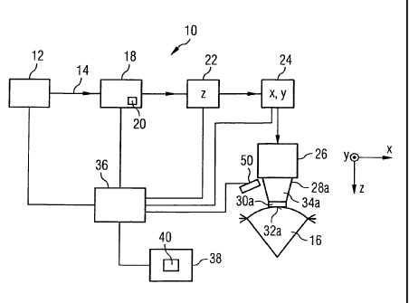
Figs. la and lb show a laser system 10 comprising a laser apparatus for
focusing a
laser beam 14 at a focus point within an eye 16.
CA 02868839 2014-09-29
WO 2014/029407
PCT/EP2012/003558
- 7 -
The laser system comprises a laser source 12. The laser source 12 may include,
for
example, a laser oscillator (e.g., solid-state laser oscillator); a pre-
amplifier, which
increases the pulse power of the laser pulses emitted from the oscillator and
simultaneously temporally stretches them; a subsequent pulse-picker, which
selects
individual laser pulses from the pre-amplified laser pulses of the oscillator
in order to
lower the repetition rate to a desired degree; a power amplifier, which
amplifies the
selected, still temporally stretched, pulses to the pulse energy needed for
the
application; and a pulse compressor, which temporally compresses the pulses
output
from the power amplifier to the pulse duration desired for the application.
The laser source 12 generates a pulsed laser beam 14. The pulse duration of
the
radiation pulses is chosen either to generate reflected or backscattered light
signals
for diagnostic purposes or to create incisions in the corneal tissue of an eye
16 of a
patient for treatment purposes. The radiation pulses of the laser beam 14 have
a
pulse duration in the nanosecond, picosecond, femtosecond or attosecond range.
The laser beam 14 generated by the laser source 12 furthermore has a pulse
repetition rate suitable for the particular application. The repetition rate
of the
radiation pulses emitted from the laser device 10 and directed onto the eye 16
may
correspond to the repetition rate of the radiation pulses that are generated
at the
output of the laser source 12. Alternatively, a portion of the radiation
pulses emitted
from the laser source 12 may be blanked by means of an optical switch 18
arranged
in the radiation path of the laser beam 14 such that they do not reach the eye
16.
This may be required by, e.g., a predetermined machining profile for the eye
16.
The optical switch 18, which is also called a pulse modulator, may be, for
example,
an acousto-optical modulator or an electro-optical modulator. Generally, the
optical
switch 18 may include arbitrary optically active elements that enable a rapid
blanking
of individual laser pulses. The optical switch 18 may include, for example, a
beam
trap, indicated schematically at 20, which serves to absorb radiation pulses
to be
blanked. The optical switch 18 can deflect such radiation pulses to be blanked
from
the normal beam path of the radiation pulses of the laser beam 14 and direct
them
onto the beam trap 20.
Further optical components that are arranged in the beam path of the laser
beam 14
include a z-controller 22 and an x-y controller 24. The z-controller 22, on
the one
hand, controls the longitudinal location of the focal point of the laser beam
14; the x-
y controller 24, on the other hand, controls the transverse location of the
focal point.
CA 02868839 2014-09-29
WO 2014/029407
PCT/EP2012/003558
- 8 -
A coordinate frame that represents the x-y-z directions in the region of the
eye 16
has been drawn in Figs. la and lb for the purpose of illustration. In this
context, the .
term 'longitudinal' refers to the direction of beam propagation, which
conventionally
is designated as the z-direction. Similarly, 'transverse' refers to a
direction transverse
to the direction of propagation of the laser beam 14, which conventionally is
designated as the x-y plane.
To achieve a transverse deflection of the laser beam 14, the x-y controller 24
may
include, for example, a pair of galvanometrically actuated scanner mirrors
that are
io capable of tilting about mutually perpendicular axes. The z-controller
22 may include,
for example, a longitudinally adjustable lens or a lens of variable refractive
power or
a deformable mirror with which the divergence of the laser beam 14, and
consequently the z-position of the beam focus, can be controlled. Such an
adjustable
lens or mirror may be included in a beam expander that expands the laser beam
14
emitted from the laser source 12. The beam expander may, for example, be
configured as a Galilean telescope.
The laser apparatus of the embodiments shown in Figs. la and lb comprise a
focusing objective 26 arranged in the beam path of the laser beam 14. The
focusing
objective 26 serve to focus the laser beam 14 onto a desired location on or in
the
eye 16, such as within the cornea. The focusing objective 26 is may be an f-
theta
focusing objective.
The optical switch 18, the z-controller 22, the x-y controller 24 and the
focusing
objective 26 do not have to be arranged in the order represented in Figs. la
and lb.
For example, the optical switch 18 may, without loss of generality, be
arranged in the
beam path downstream of the z-controller 22. If desired, the x-y controller 24
and z-
controller 22 may be combined to form a single structural unit. The order and
grouping of the components shown in Figs. la and lb is in no way to be
understood
as restrictive.
On the beam-exit side of the focusing objective 26, an applanation element 30a
constitutes an abutment interface for the cornea of the eye 16. The
applanation
element 30a is transparent or translucent to the laser radiation. On the
underside,
facing towards the eye, the applanation element 30a includes an abutment face
32a
for the cornea of the eye 16. In the exemplary case shown, the abutment face
32a is
realised as a plane surface. In certain embodiments, the abutment face 32a is
convex or concave. The abutment face 32a levels the cornea when the
applanation
CA 02868839 2014-09-29
WO 2014/029407
PCT/EP2012/003558
- 9 -
element 30a is pressed against the eye 16 with appropriate pressure or when
the
cornea is aspirated onto the abutment face 32a by vacuum. As shown in Figs. la
and
lb, the eye 16 is bearing against the planar abutment face 32a of the
applanation
-
element 30a.
The applanation element 30a, which in the case of plane-parallel design is
ordinarily
designated as the applanation plate, is fitted to the narrower end of a
conically
widening carrier sleeve 34a. The connection between the applanation element
30a
and the carrier sleeve 34a may be permanent, for example by virtue of adhesion
bonding, or it may be detachable, for instance, by virtue of a screw coupling.
It is
also conceivable to use a single optical injection-moulded part that functions
as both
the carrier sleeve 34a and the applanation element 30a. In a manner not
represented in detail, the carrier sleeve 34a has coupling structures at its
wider
sleeve end, which in the drawing is the upper end. The coupling structures are
suitable for coupling the carrier sleeve 34a onto the focusing objective 26.
The laser system 10 also comprises at least one detection element 50 that is
adapted
to detect light, which is formed as a frequency multiple at the focus and
backscattered toward the detection element 50, in order to produce image
zo information about the inner corneal tissue. The detection element 50 may
be located
either inside or outside the carrier sleeve 34a.
In the embodiment shown in Fig. lb, a beam splitter 51, which may be a
dichroic
splitter, is provided in the beam path, and the detection element 50 is
located in a
position such that a portion of light deflected by the beam splitter 51 is
deflected
onto the detection element 50. In other words, the detection element 50 may be
arranged such that the backscattered light, which is formed as a frequency
multiple,
is directly backscattered to the detection element 50 (Fig. la).
Alternatively, the
detection element 50 may be arranged such that the backscattered light is
backscattered to the beam splitter 51 arranged in the beam path and is then
deflected to the detection element 50 (Fig. lb). The detection element 50 is a
photodetector, for example, a photomultiplier tube (PMT), an Avalanche Photo
Diode
(APD), a high-gain Silicon Photomultiplier (SPM), or another type of
amplifying light
sensor.
The laser source 12, the optical switch 18, the detection element 50, and the
two
scanners 22, 24, are controlled by a control computer 36, which operates in
accordance with a control program 40 stored in a memory 38. The control
program
CA 02868839 2014-09-29
WO 2014/029407
PCT/EP2012/003558
- 10 -
40 contains instructions (e.g., program code) that are executed by the control
computer 36 so as to control the location of the beam focus of the laser beam
14 in
the cornea, in the lens or at another location of the eye 16 bearing against
the
contact element 30a.
The laser system 10 may also comprise an interface module (not shown)
connected
to control computer 36 to allow a user to input commands to the control
computer
36. The interface module may comprise a screen or monitor to enable the user
to
view status information about components of the laser system and/or data
collected
io by at least one of the detection elements 50.
Figs. 2 and 3 schematically illustrate the cornea of a human eye. To
illustrate the
layers of the human cornea, the corneal layers of eye 16 are shown magnified
in Fig.
3, as discussed in the introduction.
Fig. 4 schematically illustrates the components of the laser apparatus. As
shown in
Fig. 4, the laser apparatus comprises optics 42 that are adapted to focus a
laser
beam 14 within a corneal tissue of an eye 16. The optics 42 comprise at least
the z-
controller 22 and focusing objective 26 of the laser system 10 of Figs. la and
lb, but
may also comprise the laser source 12, pulse-width modulator 18, and/or x-y
controller 24 shown in Figs. la and lb.
The laser apparatus also comprises at least one detection element 50, which is
adapted to detect light that is formed as a frequency multiple at the focus
and
backscattered or forward emitted toward the detection element, to produce
image
information about the inner corneal tissue.
When the laser apparatus is used for therapeutic purposes, a beam 14 is
generated
with sufficient beam energy at the focus 80, which is located at a depth 82,
so as to
cut an incision pattern. In the course of a machining of the cornea, such an
incision
pattern completely severs a corneal tissue volume from the surrounding corneal
tissue, as part of a corneal lenticule extraction or a corneal keratoplasty.
If desired,
this incision pattern may additionally subdivide the severed tissue volume
into a
plurality of volume segments individually separated from one another.
When the laser apparatus is used for diagnostic or scanning purposes, intense
light
at the focus 80 of the laser beam 14 causes highly polarized and
noncentrosymmetric
CA 02868839 2014-09-29
WO 2014/029407
PCT/EP2012/003558
- 11 -
tissues, such as collagen, to produce light at a frequency multiple of the
input
frequency.
The higher-frequency light occurs partially in the form of Second Harmonic
Generated (SHG) signals, which are created when two near-infrared photons
interact
with highly polarized, noncentrosymmetric materials to generate a single,
visible
photon with twice the energy and half the wavelength.
Higher-frequency light can also be produced in the form of Third Harmonic
Generated (THG) signals, which are created when three near-infrared photons
interact with highly polarized, noncentrosymmetric materials to generate a
single,
visible photon with three times the energy and one third the wavelength. While
only
the SHG and TI-IG signals are described in detail here, it is noted that
higher-order
harmonic signals are also possible.
The light within the laser beam 14 causes collagen structures of the cornea
that are
located within the focus 80 to emit photons at frequency multiples of the
frequency
of the light which forms the laser beam 14. In one example, if the light
within the
laser beam 14 has a wavelength of A =1030 nm, then a SHG signal is produced at
the frequency AsHG=515 nm, and a TFIG signal is produced at ATHG=343 nm.
When excited by the laser beam 14, higher-frequency light in the form of SHG
and
THG signals is emitted from the collagen structures of the cornea. The higher-
frequency light is scattered in all directions, producing signals in the form
of
backscattered beams 86. The detection element 50 detects these signals and
uses
them to produce image information about the inner corneal tissue.
The diameter of the focus 80 of the laser beam 14 may be between approximately
1
pm and 10 pm. The diameter of the focus 80 of the laser beam 14 is selected to
exceed the size of the structures or cells which are to be examined, e.g., the
diameter of the focus 80 may be set to 1.5 pm.
The z-controller 22 of the laser system 10 is adapted to vary the depth 82 of
the
focus 80 within the eye 16. Furthermore, the laser source 12 of the laser
system 10
is adapted to vary the wavelength of the light in the laser beam 14.
During diagnostic use, the wavelength of the light in the laser beam 14 can be
varied
between 700 and 1050 nm according to the depth of the focus 80 within the eye
16.
CA 02868839 2014-09-29
WO 2014/029407
PCT/EP2012/003558
- 12 -
Light with longer wavelengths travels more readily through the material of the
eye
16, and therefore longer wavelengths can be used to examine material which is
further removed from the outer surface of the eye 16.
Moreover, the pulse modulator 18 of the laser system 10 is adapted to vary the
pulse
energy of the laser beam 14. For example, the pulse energy of the laser beam
14
may be varied in the range of 0.5 IA to 0.05 pi
In operation, a diagnostic scan may be performed by varying the pulse energy
of the
laser beam 14, such that the beam energy in the focus 80 of the laser beam 14
is
lower than an energy required for photodisruption of the corneal tissue. The
laser
beam 14 is then focused at a focus 80 within the cornea of the eye 16, and the
backscattered light 86 that is formed as a frequency multiple at the focus 80
is
detected by the detection element 50 as an image-producing signal, to produce
image information about the inner corneal tissue.
To compile three-dimensional image information, the laser beam 14 is
successively
focused at focusses 80 of varying depth 82 within the cornea. When performing
diagnostic scans, the laser beam operates in a range of wavelengths between
700
zo and 1050 nm. At successive depths 82, the wavelength of the light which
forms the
laser beam 14 is increased, as the distance of the focus 80 from the outer
surface of
the eye 16 increases. Alternatively, a single wavelength within the range of
700-1050
nm may be used for multiple depths 82 or for all of the depths 82 within the
eye 16.
After the diagnostic scan of the corneal tissue is complete, the pulse energy
of the
laser beam 14 is increased, such that the beam energy in the focus 80 of the
laser
beam 14 exceeds the energy required for photodisruption of the corneal tissue.
At
this point, surgery can begin or resume, and the laser system 10 is used for
cutting
and/or reshaping of corneal tissue.
In summary, the pulse energy of the laser beam 14 can be chosen such that the
beam energy in the focus 80 of the laser beam 14 is above or below the
photodisruptive energy of collagen. As such, the laser apparatus is
alternately usable
for either cutting/reshaping corneal tissue during surgery, or generating
SHG/'THG
signals which are collected by the detection element 50 to produce diagnostic
information about the cornea. In this way, a single laser system 10 can be
alternately
used to provide either diagnostic or therapeutic functionality.