Note: Descriptions are shown in the official language in which they were submitted.
CA 02869044 2014-10-30
SURGICAL APPARATUS
BACKGROUND
Technical Field
[0001] The present disclosure relates to a surgical apparatus. More
specifically, the
present disclosure relates to a surgical stapler including firing assemblies
configured to control
tissue gap distance between jaw members of the stapler when the jaw members
are in a clamping
configuration and the surgical stapler is fired.
Description of Related Art
100021 Surgical staplers configured to clamp and staple tissue are known.
Such staplers
may include a tool assembly that is supported at a distal end of a shaft of
the stapler. The tool
assembly may, for example, include an anvil and a cartridge including a
plurality of fasteners
that are configured to staple tissue (e.g., occlusion of vascular structure
during a transplant
procedure).
100031 To staple tissue with such staplers, tissue can be positioned
between the cartridge
and anvil, and the anvil can be approximated towards the cartridge to clamp
the tissue. Once
tissue is clamped, the stapler can be fired to advance the drive assembly of
the stapler distally
through the cartridge to eject the plurality of surgical fasteners
sequentially from the cartridge to
staple tissue.
100041 In addition to the mechanisms recited to fire the plurality of
fasteners,
conventional staplers may further include a structure configured to control
tissue gap distance
between the anvil and the cartridge of the tool assembly during firing of the
stapler.
1
CA 02869044 2014-10-30
100051 While the aforementioned staplers may be satisfactory for the
above uses, there
may exist a need for a simpler design for firing surgical fasteners and/or
approximating a
cartridge towards an anvil. There is also a need for a firing assembly that
takes up less space, as
well as a need for an alternative approximation assembly and/or method.
SUMMARY
100061 An aspect of the present disclosure provides a surgical stapling
apparatus. The
surgical stapling apparatus includes an actuating device including an
elongated shaft. A tool
assembly is disposed on a distal end of the shaft. The tool assembly may be
removably
couplable to the distal end of the shaft of the surgical stapling apparatus.
The tool assembly
includes a first jaw member supporting a cartridge assembly having a plurality
of surgical
fasteners, and a second jaw member supporting an anvil. The first jaw member
is movable in
relation to the second jaw member between a spaced position and an
approximated position.
One of the first and second jaw members includes a cantilever at a proximal
end thereof. The
cantilever may be in the form of a bridge that extends transverse in relation
to a longitudinal axis
defined through the shaft of the surgical stapling apparatus. A firing cam bar
assembly is
slidably disposed within the tool assembly. The firing cam bar assembly
includes a cam surface
configured to engage the cantilever to move the first and second jaw member
towards the
approximated position and a distal end configured to deploy the plurality of
surgical fasteners
from the cartridge as the firing cam bar assembly is translated distally
through the tool assembly.
100071 The firing cam bar assembly may include a first firing cam bar
having an
elongated configuration and a distal portion defining the cam surface. The
surgical stapler may
further include a second firing cam bar having an elongated configuration and
a distal portion
2
CA 02869044 2014-10-30
defining the cam surface, the second firing cam bar seated within the first
firing cam bar. The
cartridge may include a plurality of pushers and the distal portions of the
first and second firing
cam bars are configured to contact the plurality of pushers of the cartridge
to deploy the plurality
of surgical fasteners from the cartridge.
100081 The cam surface of the firing cam bar assembly may include a first
cam portion
disposed distally and at an angle in relation to a second cam portion. The
second cam portion of
the cam surface may taper inwardly toward a proximal end of the firing cam bar
assembly.
100091 A resilient member may be provided on the cartridge for biasing
the cartridge
radially away from the anvil. The resilient member may include a proximal end
that is coupled
to a proximal end of the cartridge and a distal end that is positioned to
contact at least a portion
of the anvil. The proximal end of the resilient member may include two finger
portions that are
seated within two corresponding apertures defined at the proximal end of the
cartridge.
[0010J An aspect of the present disclosure provides a reload configured
for use with a
surgical stapling apparatus. The reload includes a shaft including a proximal
end, which is
adapted to couple to a surgical apparatus, and distal end. A tool assembly is
disposed on the
distal end of the shaft. The tool assembly includes a first jaw member
supporting a cartridge
assembly having a plurality of surgical fasteners, and a second jaw member
supporting an anvil.
The first jaw member is movable in relation to the second jaw member between a
spaced
position and an approximated position. One of the first and second jaw members
includes a
cantilever at a proximal end thereof. The cantilever may be in the form of a
bridge that extends
transverse in relation to a longitudinal axis defined through the shaft of the
surgical stapling
apparatus. A firing cam bar assembly is slidably disposed within the tool
assembly. The firing
cam bar assembly includes a cam surface configured to engage the cantilever to
move the first
3
CA 02869044 2014-10-30
and second jaw member towards the approximated position and a distal end
configured to deploy
the plurality of surgical fasteners from the cartridge as the firing cam bar
assembly is translated
distally through the tool assembly.
100111 An aspect of the present disclosure provides a surgical stapling
apparatus. The
surgical stapling apparatus includes an actuating device including an
elongated shaft. A tool
assembly is disposed on a distal end of the shaft. The tool assembly is
removably couplable to
the distal end of the shaft of the surgical stapling apparatus. The tool
assembly includes a first
jaw member supporting a cartridge assembly having a plurality of fasteners and
a sled positioned
to eject the fasteners from the cartridge assembly and a second jaw member
supporting an anvil.
The first jaw member is movable in relation to the second jaw member between
spaced and
approximated positions. A sled pusher assembly includes a sled pusher having a
distal end
configured to engage the sled of the cartridge assembly. A drive beam assembly
includes a latch
assembly having a latch releasably coupled to the sled pusher assembly. Distal
translation of the
drive beam assembly from a retracted position towards an advanced position
effects movement
of the first and second jaw members to the approximated position and
disengages the latch of the
latch assembly from the sled pusher assembly to facilitate distal movement of
the sled pusher
independently of the drive beam assembly. Distal movement of the sled pusher
independently of
the drive beam assembly also advances the distal end of the sled pusher into
engagement with the
sled of the cartridge assembly to eject the plurality of fasteners from the
cartridge assembly.
100121 The latch assembly may include a collar which is coupled to a
proximal end of the
drive beam assembly and may include an aperture configured to receive a
support member of the
sled pusher assembly. The support member of the sled pusher assembly may
include at least one
aperture that is configured to receive the latch of the latch assembly.
4
CA 02869044 2014-10-30
100131 The drive beam assembly may include an I-beam having a sidewall
defining a
notch, the sled pusher being received within the notch. The I-beam may be
positioned to cam the
first and second jaw members to the approximated position when the drive beam
assembly is
translated distally.
[0014] The latch assembly may include at least one spring configured to
bias the latch of
the latch assembly into the aperture defined in the support member of the sled
pusher assembly.
The aperture of the support member may be defined by a proximal wall portion
of the sled
pusher assembly. The proximal wall portion may be configured to engage the
latch of the latch
assembly to maintain the drive beam assembly and the sled pusher coupled with
one another.
100151 The elongated shaft may include upper and lower housing portions,
and at least
one of the upper and lower housing portions includes at least one stop member
configured to
contact a proximal end of the collar of the latch assembly when the drive beam
assembly is
translated distally. The latch may include a lateral offset extension, and
wherein at least one of
the upper and lower housing portions of the elongated shaft includes at least
one ramp portion
configured to be engaged by the lateral offset extension to effect movement of
the latch out of
engagement with the proximal wall portion when the drive beam assembly is
moved distally so
as to allow the sled pusher assembly to move distally in relation to the drive
beam assembly.
100161 A resilient member may be provided on the cartridge for biasing
the cartridge
assembly radially away from the anvil. The resilient member may include a
bottom portion that
is coupled to a proximal end of the cartridge and a top portion that is
positioned to contact at
least a portion of the anvil. The bottom portion of the resilient member may
be seated within a
corresponding slot defined at the proximal end of the cartridge assembly. The
bottom portion of
CA 02869044 2014-10-30
the resilient member may include at least one detent that couples to a
corresponding indent
disposed on the cartridge assembly adjacent the slot.
[00171 An
aspect of the present disclosure provides a reload configured for use with a
surgical stapling apparatus. The reload includes a shaft including a proximal
end and distal end.
The proximal end adapted to couple to a surgical apparatus. A tool assembly is
disposed on the
distal end of the shaft. The tool assembly includes a first jaw member
supporting a cartridge
assembly having a plurality of fasteners and a sled positioned to eject the
fasteners from the
cartridge assembly and a second jaw member supporting an anvil. The first jaw
member is
movable in relation to the second jaw member between spaced and approximated
positions. A
sled pusher assembly includes a sled pusher having a distal end configured to
engage the sled of
the cartridge assembly. A drive beam assembly includes a latch assembly having
a latch
releasably coupled to the sled pusher assembly. Distal translation of the
drive beam assembly
from a retracted position towards an advanced position effects movement of the
first and second
jaw members to the approximated position and disengages the latch of the latch
assembly from
the sled pusher assembly to facilitate distal movement of the sled pusher
independently of the
drive beam assembly. Distal movement of the sled pusher independently of the
drive beam
assembly also advances the distal end of the sled pusher into engagement with
the sled of the
cartridge assembly to eject the plurality of fasteners from the cartridge
assembly.
BRIEF DESCRIPTION OF THE DRAWING
100181
Various embodiments of the present disclosure are described hereinbelow with
references to the drawings, wherein:
6
CA 02869044 2014-10-30
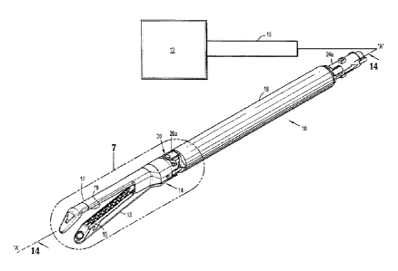
100191 Fig. IA is a perspective view of a reload according to an
embodiment of the
instant disclosure, the reload configured for use with a surgical apparatus
that is shown
schematically in Fig. 1A;
[0020] Fig. 1B is a perspective view of one type of surgical stapler that
may be utilized
with the reload shown in Fig. IA;
100211 Fig. 2 is an exploded view of the reload shown in Fig. lA with
parts separated;
[0022] Fig. 3 is a perspective view of a firing cam bar assembly of the
reload shown in
Figs. 1 and 2;
[0023] Fig. 4 is the indicated area of detail shown in Fig. 3;
[0024] Fig. 5 is a side view of the firing cam bar assembly shown in Fig.
3;
[0025] Fig. 6 is an exploded view of the firing cam bar assembly shown in
Fig. 3 with
parts separated;
100261 Fig. 7 is the indicated area of detail shown in Fig. 1A;
100271 Fig. 8 is a perspective view of the reload shown in Fig. IA with an
outer tube of
the reload removed;
[0028] Fig. 9 is the indicated area of detail shown in Fig. 8;
[0029] Fig. 10 is a perspective view of the reload shown in Fig. IA with
parts removed
illustrating the firing cam bar assembly coupled to a cartridge of a tool
assembly of the reload;
[0030] Fig. 11 is the indicated area of detail shown in Fig. 10;
[0031] Fig. 12 is a perspective view of the reload shown in Fig. lA with
parts removed
illustrating a cantilever of the cartridge in contact with the firing cam bar
assembly;
100321 Fig. 13 is the indicated area of detail shown in Fig. 12;
100331 Fig. 14 is a cross sectional view taken along section line 14-14 in
Fig. 1A;
7
CA 02869044 2014-10-30
100341 Fig. 15 is the indicated area of detail shown in Fig. 14;
100351 Fig. 16 is a partial, cross sectional view of a distal end of the
reload shown in Fig.
lA illustrating the firing cam bar assembly being translated through the
cartridge to fire fasteners
of the cartridge;
100361 Fig. 17 is the indicated area of detail shown in Fig. 16;
100371 Fig. 18 is a partial, cross sectional view of the distal end of
the reload shown in
Fig. 15 illustrating a cam surface of the firing cam bar assembly sliding
along the cantilever of
the cartridge as the firing cam bar assembly is being translated through the
cartridge to fire
fasteners of the cartridge;
100381 Fig. 19 is a partial, cross sectional view of the distal end of
the reload shown in
Fig. 15 illustrating a pusher contacting surface of the firing cam bar
assembly pushing a pusher
of the cartridge as the firing cam bar assembly is being translated through
the cartridge to fire
fasteners of the cartridge;
100391 Fig. 20 is a partial, cross sectional view of the distal end of
the reload shown in
Fig. 15 illustrating the cam surface of the firing cam bar assembly and the
cantilever of the
cartridge in contact with one another to maintain a specific tissue gap
distance between the
cartridge and an anvil of the tool assembly;
100401 Fig. 21 is a perspective view of a reload according to another
embodiment of the
instant disclosure, the reload configured for use with the surgical apparatus
that is shown
schematically in Fig. 1A;
100411 Fig. 22 is an exploded view of the reload shown in Fig. 21 with
parts separated;
100421 Fig. 23 is a perspective view of a cartridge assembly of the reload
shown in Fig,
21;
8
CA 02869044 2014-10-30
100431 Fig. 24 is an exploded view of the cartridge assembly shown in
Fig. 23 with parts
separated;
[0044] Fig. 25 is a perspective view of a second jaw member of the reload
shown in Fig.
21;
[0045] Fig. 26 is an exploded view of the second jaw member shown in Fig.
25 with
parts separated;
[0046] Fig. 27 is a perspective view of a drive beam assembly and latch
assembly of the
reload shown in Fig. 21;
[0047] Fig. 28 is an exploded view of the drive beam and latch assembly
shown in Fig.
27 with parts separated;
[0048] Fig. 29 is a perspective view of a sled pusher assembly of the
reload shown in Fig.
21;
[0049] Fig. 30 is an exploded view of the sled pusher assembly shown in
Fig. 29 with
parts separated;
[0050] Fig. 31 is a partial, perspective view of the reload shown Fig. 21
with a distal end
of the reload shown in an unclamped configuration;
[0051] Fig. 32 is a partial, perspective view of the reload shown in Fig.
21 with parts
removed illustrating the drive beam assembly and latch assembly when the
distal end of the
reload is in the unclamped configuration shown in Fig. 31;
100521 Fig. 33 is the indicated area of detail shown in Fig. 32;
[0053] Fig. 34 is a cross sectional view taken along section line 34-34 in
Fig. 31;
[0054] Fig. 35 is the indicated area of detail shown in Fig. 34;
9
CA 02869044 2014-10-30
[0055] Fig. 36 is a partial, perspective view of the reload shown in Fig.
21 with a distal
end of the reload shown in a clamped configuration;
[0056] Fig. 37 is a partial, perspective view of the reload shown in Fig.
21 with parts
removed illustrating the drive beam assembly and latch assembly when the
distal end of the
reload is in the clamped configuration shown in Fig. 36;
[0057] Fig. 38 is the indicated area of detail shown in Fig. 37;
[0058] Fig. 39 is a perspective view of an upper shaft portion of the
reload shown in Fig.
21;
[0059] Fig. 40 is a cross sectional view of the reload shown in Fig. 21
with the distal end
of the reload shown in the clamped configuration;
[0060] Fig. 41 is the indicated area of detail shown in Fig. 40;
100611 Fig. 42 is a partial, perspective view of the reload shown in Fig.
21 with parts
removed illustrating the sled pusher assembly shown in Fig. 29 as the sled
pusher assembly is
being fired;
[0062] Fig. 43 is a cross sectional view of the reload shown in Fig. 21
with the reload
shown in the clamped configuration and the sled pusher assembly being fired;
and
[0063] Fig. 44 is the indicated area of detail shown in Fig. 43.
DETAILED DESCRIPTION
100641 Detailed embodiments of the present disclosure are disclosed
herein; however, the
disclosed embodiments are merely examples of the disclosure, which may be
embodied in
various forms. Therefore, specific structural and functional details disclosed
herein are not to be
interpreted as limiting, but merely as a basis for the claims and as a
representative basis for
CA 02869044 2014-10-30
teaching one skilled in the art to variously employ the present disclosure in
virtually any
appropriately detailed structure.
[0065] Embodiments of the present disclosure are described in detail with
reference to
the drawing figures wherein like reference numerals identify similar or
identical elements. As
used herein, the term "distal" refers to the portion that is being described
which is further from a
user, while the term "proximal" refers to the portion that is being described
which is closer to a
user.
[0066] Referring initially to Fig. 1A, a reload 10 in accordance with the
present
disclosure is shown. The reload 10 may be configured to be coupled to a
variety of different
surgical actuating devices, shown schematically as 12 in Fig. 1A, including
manually operated
actuation devices, robotically controlled actuation devices, electromechanical
actuation devices,
motorized actuation devices, etc. The surgical actuating device 12 includes a
shaft assembly 16
having a distal end configured to releasably support the reload 10.
100671 In one embodiment illustrated in Fig. 1B, the surgical actuating
device 12 is a
manually operated stapler 212 which includes a handle assembly 214 and a shaft
assembly 216
that engages and supports the reload 10. The handle assembly 214 includes a
pair of retraction
knobs 218 that is configured to return the stapler 212 to a retracted
configuration. For a more
detailed description of the operation and the operative components of the
stapler 212, reference
is made to commonly-owned U.S. Patent No. 5,865,361 to Milliman, the entire
contents of which
are hereby incorporated by reference.
100681 Fig. 2 is a perspective view of the reload 10 with parts
separated. The reload 10
includes an outer tube 18 that houses a shaft assembly 20 configured to couple
the reload 10 to
the shaft assembly 16 of the actuating device 12 (see Fig. IA). The shaft
assembly 20 includes
11
CA 02869044 2014-10-30
an upper housing portion 22a and lower housing portion 22b that, when coupled
to one another,
house components of the reload 10. Proximal ends 24a, 24b of the upper and
lower housing
portions 22a, 22b are configured to releasably couple with the distal end of
the shaft assembly 16
of the actuating device 12 (e.g., see the '361 patent). A distal end of the
housing portions 22a,
22b of the shaft assembly 20 supports upper and lower coupling members 26a,
26b respectively.
A distal end of each of coupling members 26a, 26b is configured to pivotally
engage upper and
lower pivot portions 28a, 28b, respectively, of a pivot assembly 30 (see Fig.
1A). An articulating
link 32 is slidably positioned within the upper and lower housing portions
22a, 22b and is
configured to articulate an end effector or tool assembly 14 of the reload 10
in relation to the
shaft assembly 20.
[0069] The tool assembly 14 includes a first jaw member 13 that supports
a cartridge 15
and a second jaw member 17 that supports an anvil 19. The first jaw member 13
is pivotally
supported in relation to the second jaw member 17 between spaced and
approximated positions.
The cartridge 15 houses a plurality of pushers 9 and fasteners 11. A
dissecting tip 19a may be
secured to a distal end of the anvil 19 to facilitate positioning of the anvil
19 in relation to tissue
to be stapled. Such a dissecting tip 19a is described in U.S. Patent No.
8,348,123 which is
hereby incorporated herein by reference.
[0070] Referring also to Figs. 3-6, the shaft assembly 20 includes a
firing cam bar
assembly 34 that is releasably engaged with a central rod (not shown) of the
actuating device 12.
The firing cam bar assembly 34 is configured to move the cartridge 15 from the
spaced position
(Fig. 1B) towards the anvil 19 to the approximated position (Fig. 18) as the
firing cam bar
assembly 34 is translated distally through the tool assembly 14. A distal end
of the firing cam
bar assembly 34 is also configured to push the plurality of pushers 9 to fire
the plurality of
12
CA 02869044 2014-10-30
fasteners 11 from the cartridge 15 as the firing cam bar assembly 34 is
translated through the
cartridge 15 as will be described in further detail below.
100711 The firing cam bar assembly 34 includes a first firing cam bar 36
having an
elongated configuration defined by left and right sidewalls 37a, 37b, which
have a distal end 38.
Each of the left and right sidewalls 37a and 37b of the cam bar 36 includes a
cam surface 33
having a first cam portion 39 and a second cam portion 40. Each of the first
cam portions 39 is
disposed distally and at an angle in relation to one of the second cam
portions 40 which is
defined along a bottom/lower surface of the left and right sidewalls 37a, 37b.
Only one of the
second cam portions 40 can be seen in Figs. 3-5. The configuration of the
first cam portions 39
of the cam surface 33 facilitates movement of the first jaw member 13 towards
the second jaw
member 17 from the spaced position to the approximated position so that tissue
may be clamped
as will be described in further detail below. The second cam portions 40 are
elongated in
comparison to the first cam portions 39 and taper inwardly a distance "T"
(Fig. 5) in relation to a
longitudinal axis "B-B" of the firing cam bar assembly 34 toward a proximal
end of the firing
cam bar assembly 34 (Fig. 5). The taper "T" controls a tissue gap distance
between the first and
second jaw members 13, 17 when the first and second jaw members 13, 17 are
moved toward the
approximated position, as will be described in further detail below.
[0072] The distal end 38 of the first firing cam bar 36 includes two
pusher contacting
surfaces 42a, 42b (Figs. 4 and 6) which are aligned with the plurality of
pushers 9 of the
cartridge 15 (Fig. 19). The pusher contacting surfaces 42a, 42b are configured
to contact the
plurality of pushers 9 to deploy the plurality of surgical fasteners 11 from
the cartridge 15.
[0073] In the illustrated embodiment, the firing cam bar assembly 34
includes a second
or inner firing cam bar 44 that is similar to the first firing cam bar 36. The
first and second firing
13
CA 02869044 2014-10-30
cam bars 36, 44 form a nested configuration with one another (as best shown in
Fig. 6). The
second firing cam bar 44 has an elongated configuration defined by left and
right sidewalls 45a,
45b, which have a distal end 46. Each of the left and right sidewalls 45a and
45b of the cam bar
44 includes a cam surface 53 having a first cam portion 49 and second cam
portion 50. The first
cam portions 49 of the cam surface 53 are disposed distally and at an angle in
relation to the
second cam portions 50 (only one of the second portions 50 is shown) of the
cam surface 53.
The distal end 46 of the second firing cam bar 44 includes two pusher
contacting surfaces 48a,
48b which are aligned with the plurality of pushers 9 of the cartridge 15 to
contact the plurality
of pushers 9 to deploy the plurality of surgical fasteners 11 from the
cartridge 15 (Fig. 19).
100741 The first and second firing cam bars 36, 44 may be formed from any
suitable
material including, but not limited to, plastic, metal, etc. In embodiments,
the first and second
firing cam bars 36, 44 are formed from metal.
100751 While the firing cam bar assembly 34 has been described herein as
including first
and second firing cam bars 36, 44, greater or fewer firing cam bars may be
utilized. For
example, in embodiments, the second firing cam bar 44 may be omitted. In this
particular
embodiment, the configuration of the first firing cam bar 36 of the firing cam
bar assembly 34
may be modified to include features of the second firing cam bar 44. For
example, the left and
right sidewalls 37a, 37b of the first firing cam bar 36 may be widened at the
distal end 38 to
align with all of the rows of the plurality of pushers 9 for ejecting all of
the plurality of fasteners
11 disposed within the cartridge 15. Alternately, the second firing cam bar 44
can be omitted
with no change to the configuration of the first firing cam bar 36.
100761 Referring to Figs. 7-13, a cantilever 52 (Fig. 13) is provided at a
proximal end of
the first jaw member 13. The cantilever 52 may be monolithically formed with
the first jaw
14
CA 02869044 2014-10-30
member 13. Alternatively, the cantilever 52 may be formed as a separate
component apart from
the first jaw member 13 and coupled to the first jaw member 13 via one or more
suitable
coupling methods, e.g., welding. The cantilever 52 is disposed adjacent the
pivot assembly 30
between the lower coupling member 26b and a distal end of the articulating
link 32 (see Fig. 9
for example).
100771 In the illustrated embodiment, the cantilever 52 is in the form of
a bridge 54 that
is formed between side projections 55a, 55b that extend proximally from the
proximal end of the
first jaw member 13 (Fig. 13). The bridge 54 is disposed transverse to a
longitudinal axis "A-A"
(Fig. 7) defined through the shaft assembly 20 of the reload 10.
100781 The bridge 54 supports a cam member 57 (Fig. 2 and 13) which is
positioned to
be slidably engaged by the first and second cam portions 39, 49 and 40, 50,
respectively, of the
first and second firing cam bars 36, 44 when the firing cam bar assembly 34 is
advanced distally
within the cartridge 15, as will be described in greater detail below. The cam
member 57 may be
slanted (as shown in the illustrated embodiment) or otherwise configured to
operate in
conjunction with the taper "T" of the second cam portions 40, 50 of the first
and second cam bars
36, 44, respectively, to control the size of the tissue gap between the first
and second jaw
members 13, 17 when the first and second jaw members 13, 17 are in the
approximated
configuration. The cam member 57 may be coupled to the bridge 54 via one or
more suitable
coupling methods, e.g., adhesive, welding, etc. Alternatively, the cam member
57 may be
omitted and the bridge 54 may be integrally formed with a cam surface
configured to control the
size of the tissue gap. In accordance with the instant disclosure, the bridge
54 engages the firing
cam bars 36, 44 to close the first and second jaw members 13, 17 in both the
linear and
articulated positions.
CA 02869044 2014-10-30
[0079J Referring to Fig. 9, the cantilever 52 defines an aperture 58
between the side
projections 55a, 55b and the bridge 54. The aperture 58 receives a rivet 59
(Fig. 9) for coupling
the lower coupling member 26b to the lower portion 28b of the pivot assembly
30 during
manufacture of the reload 10.
100801 Referring to Figs. 2, 14, and 15, a resilient member 56 is
provided on the cartridge
15 and is positioned to bias the cartridge 15 radially away from the anvil 19
towards the spaced
position. The resilient member 56 includes a proximal end 60 that is coupled
to a proximal end
of the cartridge 15 and a distal end 62 that is positioned to contact at least
a portion of the anvil
19. In the illustrated embodiment, the proximal end 60 of the resilient member
56 includes two
finger portions 64a, 64b that seat within two corresponding apertures 66a, 66b
of suitable
configuration defined at the proximal end of the cartridge 15 (see Fig. 2 and
Fig. 13).
[0081] Referring to Figs. 16 and 17, in use, prior to positioning tissue
between the first
and second jaw members 13, 17, the tool assembly 14 is in the spaced or
unapproximated
position. In this position, the distal ends 38, 46 of the first and second
firing cam bars 36, 44 are
positioned proximally of the plurality of pushers 9 and the plurality of
fasteners 11. In addition,
in this configuration an engagement portion of the first cam portions 39, 49
(see also Fig. 6) of
the first and second firing cam bars 36, 44 is positioned proximally of the
cam member 57. As
discussed above, the resilient member 56 is positioned to urge the jaw member
13 to the spaced
or unapproximated position.
[0082] Referring to Fig. 18, when the firing cam bar assembly 34 is
advanced distally,
the first cam portions 39, 49 of the first and second firing cam bars 36, 44
and engage the cam
member 57 of the bridge 54 and pivot the first jaw member 13 including the
cartridge 15 towards
the anvil 19 of the second jaw member 17 to move the jaw member 13 including
the cartridge 15
16
CA 02869044 2014-10-30
to the clamped or approximated configuration. In this example, the cartridge
is pivotably
attached to the second jaw member. However, any of the embodiments disclosed
herein can
have a first jaw member, or second jaw member, or both that are pivotably
movable.
[00831 Referring to Fig. 19, continued distal translation of the firing
cam bar assembly 34
moves the distal ends 36, 48 of the first and second firing cam bars 36, 44
into contact with the
plurality of pushers 9 sequentially to eject the plurality of fasteners 11
from the cartridge 15 and
into the anvil 19 to staple clamped tissue. In accordance with the present
disclosure, as the firing
cam bar assembly 34 is translated through the cartridge 15, engagement of the
cam member 57
on the bridge 54 with the taper "T" (Fig. 15) on the second cam portions 40,
50 of the first and
second firing cam bars 36, 44 controls the position of the jaw member 17 in
relation to the jaw
member 13 to selectively maintain a desired tissue gap distance between the
first and second jaw
members 13, 17 (Fig. 20). In accordance with the instant disclosure, the
degree of the taper "T"
on the second cam portions 40, 50 of the first and second firing cam bars 36,
44 may be uniform
or non-uniform to selectively control the tissue gap distance during
translation of the cam bar
assembly 34 through the cartridge 15. It is noted that the taper "T" may
define a positive or
negative slope in the proximal direction to provide the proper or desired
tissue gap distance.
100841 The unique configuration of the jaw member 13 including the firing
cam bar
assembly 34 and cantilever 52 provides a simple design for approximating and
controlling the
tissue gap between the cartridge 15 and the anvil 19. Additionally, the
presently disclosed tool
assembly 14 allows for the tissue gap between the first and second jaw members
13, 17 to be
accurately controlled by the second cam portions 40, 50 of the first and
second firing cam bars
36, 44 as the firing cam bar assembly 34 is advanced.
17
CA 02869044 2014-10-30
100851 In embodiments, the tool assembly 14 can be integrally formed with
the surgical
actuating device 12. In this particular embodiment, the tool assembly 14 can
be operably
coupled to an articulating assembly, e.g., the articulating assembly 30, which
may be supported
at a distal end of the shaft assembly 16 of the surgical actuating device 12.
Alternatively, the
articulating assembly 30 can be omitted and the tool assembly 14 can be
directly connected to
the distal end of the shaft assembly 16 of the surgical actuating device 12.
100861 Figs. 21-44 illustrate a reload 110 according to another
embodiment of the instant
disclosure. The reload 110 is configured for use with the stapler 212 that is
shown in Fig. 1B.
Only the features that are unique to the reload 110 are described herein.
100871 Fig. 22 is a perspective view of the reload 110 with parts
separated. The reload
includes an outer tube 118 that houses a shaft assembly 120 configured to
couple the reload 110
with the shaft assembly 216 of the actuating device 212 shown in Fig. 1B. The
shaft assembly
120 includes upper housing portion 122a and lower housing portion 122b that,
when coupled to
one another, house components of the reload 110. Proximal ends 124a, 124b of
the upper and
lower housing portions 122a, 122b, respectively, are configured to releasably
couple to the distal
end of the shaft assembly 216 of the actuating device 212 (see '361 patent for
example). A distal
end of the shaft assembly 120 includes a pair of upper and lower coupling
members 126a, 126b
that are configured to couple the shaft assembly 120 to the upper and lower
pivot portions 128a,
128b, respectively, of a pivot assembly 130 (see Fig. 21). An articulating
link 132 is slidably
positioned within the upper and lower housing portions 122a, 122b and is
configured to
articulate an end effector or tool assembly 114 of the reload 110 relative to
a longitudinal axis
"C-C" (Fig. 21) defined through the shaft assembly 120.
18
CA 02869044 2014-10-30
100881
Referring to Figs. 22-24, the tool assembly 114 includes a first jaw member
113
that supports a cartridge 115 housing a plurality of pushers 109 and fasteners
111 and a second
jaw member 117 that supports an anvil 119. The cartridge 115 supports a
resilient member 156
which is positioned to bias the cartridge 115 radially away from the anvil 119
towards an
unapproximated or spaced configuration. The resilient member 156 includes a
base portion 160
(Fig. 24) that couples to a proximal end of the cartridge 115 and an upper
portion 162 positioned
to contact at least a portion of the anvil 119. The base portion 160 of the
resilient member 156 is
seated within a corresponding slot 165 defined at the proximal end of the
cartridge 115 and
includes one or more detents 163 (one detent 163 is shown in the figures)
which is received in a
corresponding indent 166 disposed on the cartridge 115 adjacent the slot 165
to couple the
resilient member 156 to the cartridge 115 .
100891
Referring to Figs. 25 and 26, the second jaw member 117 includes a pair of
upper
rails 121a, 121b that extend longitudinally along an interior wall portion 123
of the second jaw
member 117. The upper rails 121a, 121b are separated by an elongated slot 125
which extends
along the length of the upper rails 121a, 121b. The upper rails 121a, 121b are
positioned along
the interior wall portion 123 proximal to where the top portion 162 of the
resilient member 156
contacts the interior wall portion 123 of the jaw member 117 (see Fig. 35 for
example). A
dissecting tip 157, such as disclosed in the '123 patent, may be secured to a
distal end of the
second jaw member 117 to facilitate positioning of the second jaw member 117
in relation to
tissue to be stapled.
[00901
Referring also to Figs. 27 and 28, the reload 110 (Fig. 21) includes a drive
beam
assembly 134 formed from a plurality of drive beam portions 135 that are
coupled to one another
to form a drive beam 136. A working end of the drive beam assembly 134
includes an I-beam
19
CA 02869044 2014-10-30
137 which is coupled to the distal end of the drive beam portions 135 and
includes upper and
lower flanges 139a, 139b respectively connected to each other by a strut 139c.
Unlike
conventional 1-beams, the I-beam 137 does not include a knife or cutting blade
at a leading edge
of the strut 139c, as the I-beam 137 is not configured to sever stapled
tissue. The I-beam 137 is
translatable through the tool assembly 114 to approximate the first and second
jaw members 113
and 117 and eject fasteners 111 from the cartridge 115 as will be described in
further detail
below. The upper flange 139a is positioned within the second jaw member 117
(Fig. 26) above
the upper rails 121a, 12 lb. When the drive beam 136 of the drive beam
assembly 134 is
translated distally within the second jaw member 117, the upper flange 139
slides atop the upper
flange 139a to prevent outward movement of the second jaw member 117 in
relation to the first
jaw member 113. Similarly, the strut 139c of the I-beam is positioned through
an elongated slot
127 (see Fig. 31) that is defined through the first jaw member 113 such that
the lower flange
I39b is slidable along an exterior surface of the first jaw member 113 to
prevent outward
movement of the first jaw member 113 in relation to the second jaw member 117.
A notch 129
is defined through a side wall of the strut 139c, the significance of which is
described in greater
detail below.
100911 A
latch assembly 140 is coupled to a proximal end of the drive beam assembly
134. The latch assembly 140 includes a latch body 141 including a collar 142
defining bottom
and top slots 144 (only the top slot 144 is shown). The slots 144 are
configured to receive a
proximal end of the drive beam 136. A longitudinal aperture 146 of suitable
configuration is
defined through the collar 142 and is in general alignment with an elongated
proximal portion
148 of the latch body 141. The latch body 141 of the latch assembly 140
includes a pair of
opposing support members 149a, 149b which support a pivot pin 151. A
protrusion 170 extends
CA 02869044 2014-10-30
upwardly from the latch body of the latch assembly 140 adjacent the collar 142
and is configured
to support a spring 171.
100921 The latch assembly 140 includes a latch 150 having a generally
elongated
configuration including a distal portion 152, a medial portion 154 and a
proximal portion 158. A
transverse aperture 153 extends through the medial portion 154 and is
configured to receive the
pivot pin 151 for pivotally securing the latch 150 to the latch body 141 of
the latch assembly
140. The distal portion 152 of the latch 150 is positioned to contact the
spring 171 such that the
spring 171 urges a proximal end 172 of the proximal portion 158 of the latch
150 downwardly
towards the proximal portion 148 of the latch assembly 140 (as best shown in
Fig. 27). A
protrusion 164 is provided on a bottom surface and at the proximal end 172 of
the proximal
portion 158 of the latch assembly 150. A lateral offset extension 173 is also
provided at the
proximal end 172 of the latch assembly 150 and is configured to move the latch
150 upwardly
against the bias of the spring 171, as will be described in greater detail
below.
100931 Referring to Figs. 29 and 30, a sled pusher assembly 174 is
illustrated. The sled
pusher assembly 174 includes an elongated support member 176 which has a
distal end that
engages a sled pusher 178 and a proximal end which supports a coupling
assembly 180. The
distal end of the support member 176 defines a slit 181 and a pair of
apertures 182 (only one
aperture 182 is shown). The apertures 182 extend through the slit 181 and
receive a pin 183,
rivet or the like. The slit 181 is configured to receive a proximal end of the
sled pusher 178. The
pin 183 extends through an aperture 186 defined through the proximal end of
the sled pusher 178
to secure the sled pusher 178 to the support member 176. As can be appreciated
other coupling
methods could also be utilized to couple the sled pusher 178 to the support
member 176.
21
CA 02869044 2014-10-30
100941 An
aperture 184 is provided on the support member 176. The aperture 184 is
configured to receive the protrusion 164 of the latch 150 such that the
protrusion 164 contacts a
proximal wall portion 185 defining the aperture 184 (Fig. 33). In accordance
with the instant
disclosure, when the protrusion 164 is in contact with the proximal wall
portion 185, the sled
pusher assembly 174 and the and the drive beam assembly 134 are releasably
coupled to one
another such that movement of sled pusher assembly 174 effects corresponding
movement of the
drive beam assembly 134 to effect movement of the first jaw member 113 towards
the second
jaw member 117.
100951
Referring also to Figs. 32 and 33, the lower housing portion 122b supports the
drive assembly 134 including the latch assembly 140 and the sled pusher
assembly 174. The
lower housing portion 122b is configured to disengage the latch 150 of the
latch assembly 140
from the sled pusher assembly 174 to allow further distal translation of the
sled pusher assembly
174 independently of the drive beam assembly 134. Specifically, a ramp portion
188 is provided
along a top wall 189 of the lower housing portion 122b. The ramp portion 188
is configured to
contact the lateral offset extension 173 of the latch 150 to pivot the latch
150 about pivot
member 151 to raise the protrusion 164 of the latch 150 out from engagement
with the aperture
184 of the support member 176 of the sled pusher assembly 174 when the drive
beam assembly
134 and sled pusher assembly 174 are translated distally to approximate the
jaw members 113
and 117.
100961 A pair
of stops 190a are provided along an interior wall portion 191 of the lower
housing portion 122b. Stops 190a are positioned to contact a lower portion of
the collar 142 of
the latch assembly 140 to prevent further distal translation of the drive beam
assembly 134 after
the collar 142 engages the stops 190a. In the illustrated embodiment, a
corresponding pair of
22
CA 02869044 2014-10-30
stops 190b (Fig. 39) is provided on the upper housing portion 122a and is
configured to contact
an upper portion of the collar 142 of the latch assembly 140 to prevent
further distal translation
of the drive beam assembly 134 after the collar 142 engages the stops 190a.
100971 Figs. 34-44 illustrate the operation of the reload 110. Referring
to Figs. 33-35,
prior to positioning tissue between the first and second jaw members 113, 117,
the tool assembly
114 is urged to the spaced or unapproximated position by the resilient member
156 which
contacts the interior wall 123 of the second jaw member 117 (Figs. 34 and 35).
In the spaced
position, the protrusion 164 of the latch 150 is in contact with the proximal
wall portion 185
defining the aperture 184 in the support member 176 to releasably couple the
sled pusher
assembly 174 to the drive beam assembly 134 such that distal translation of
the sled pusher
assembly 174 effects corresponding movement of the drive beam assembly 134.
100981 In the spaced position of the jaw members 113 and 117, the distal
end of the
support member 176 is positioned through the longitudinal aperture 146 of the
collar 142 of the
latch assembly 140 and the sled pusher 178 is positioned within the notch 129
of strut 139c of
the 1-beam 137 to align a distal end 193 of the sled pusher 178 with a sled
187 that is provided in
the cartridge 115 (Fig. 35). The distal end 193 of the sled pusher 178 is
configured to engage a
proximal end 195 of the sled 187 when the sled pusher 178 is translated
distally into the cartridge
115. In the illustrated embodiment, the distal end 193 of the sled pusher 178
and the proximal
end 195 of the sled 187 include complementary configurations, e.g., spherical
configurations, to
facilitate engagement therebetween. The sled 187 is configured to sequentially
contact the
plurality of pushers 109 to eject the plurality of fasteners 111 from the
cartridge 115 as is known
in the art.
23
CA 02869044 2014-10-30
100991 Referring to Figs. 36-41, when the surgical actuating device 12
(Fig. 1B) is
actuated to advance the sled pusher assembly 174, the drive assembly 134 which
is releasably
coupled to the sled pusher assembly 174 is advanced distally to move the I-
beam 137 distally in
relation to the tool assembly 114. As the I-beam is moved distally, the upper
and lower flanges
139a, 139b of the I-beam 137 engage the first and second jaw members 113, 117,
respectively,
such that the first jaw member 113 is moved towards the second jaw member 117
to the clamped
or approximated position of the tool assembly 114 to clamp tissue (Fig. 36).
As noted above, the
drive assembly 134 and the sled pusher assembly 174 move in unison as a result
of the
protrusion 164 being in contact with the proximal wall portion 185 defining
the aperture 184 of
the support member 176.
1001001 As the drive assembly 134 is moved distally to move the jaw
members 113 and
117 to the clamped or approximated position, the lateral offset 173 (Fig. 38)
of the latch 150
slides up along the ramp 188 of the lower housing portion 122b and raises the
latch 150 to
disengage the protrusion 164 of the latch 140 from engagement with the
proximal wall portion
185 of the support member 176. In the approximated position of the jaw members
113 and 117,
the sled pusher assembly 174 is uncoupled from the drive assembly 134 and the
distal end 193 of
the sled pusher 178 is positioned in engagement with the proximal end 195 of
the sled 187 (as
best shown in Fig. 41).
1001011 In the approximated position, the collar 142 is in contact with
the stops 190a in
the lower housing portion 122b (Figs. 38 and 42) and the upper portion of the
collar 142 is in
contact with the stops 190b in the upper housing portion 122a. Engagement
between stops 190a
and collar 142 prevents further distal movement of the drive beam assembly
134.
24
CA 02869044 2014-10-30
[00102] Referring to Figs. 42-44, after the sled pusher assembly 174 is
uncoupled from
the drive assembly 134, further actuation of the actuating device 12 effects
independent
movement of the sled pusher assembly 174 through the aperture 146 of the
collar 142 such that
the distal end 193 of the sled pusher 178 moves distally in relation to the I-
beam 137 of the drive
assembly 134 to advance the sled 187 through the cartridge 115 into sequential
engagement with
the pushers 109 to eject the plurality of fasteners 111 from the cartridge 115
(Figs. 43 and 44).
[00103] While the reloads 10, 110 have been described herein as being
configured for use
with the stapler 212, it is within the purview of the present disclosure that
the operative
components of the reloads 10, 110 may be incorporated into a stapler with a
tool assembly
fixedly attached thereto.
[00104] The stapler 212 with either of the reloads 10, 110 attached thereto
can be utilized
to staple various tissue structures. For example, during a transplant
procedure, where blood flow
through vascular structure adjacent a transplant site needs to be controlled
or inhibited, the
stapler 212 can be utilized to staple (i.e., occlude) this vascular structure,
thereby controlling
and/or inhibiting blood flow through the vascular structure It is contemplated
that the stapler 212
with either of the reloads 10, 110 attached thereto can be utilized to staple
other types of tissue
structures and/or can be utilized in conjunction with other surgical
procedures.
[00105] While several embodiments of the disclosure have been shown in the
drawings, it
is not intended that the disclosure be limited thereto, as it is intended that
the disclosure be as
broad in scope as the art will allow and that the specification be read
likewise. Therefore, the
above description should not be construed as limiting, but merely as
exemplifications of
particular embodiments. Those skilled in the art will envision other
modifications within the
scope and spirit of the claims appended hereto.