Note: Descriptions are shown in the official language in which they were submitted.
CA 02869175 2014-10-01
WO 2013/160087
PCT/EP2013/057239
Title
Rotary-leaf/-casement drive
TECHNICAL FIELD
The present invention relates to a rotary drive for a
leaf/casement, in particular a door, a window or the
like, according to the preamble of claim 1.
PRIOR ART
Door drives are used in a widespread manner in order to
actuate door leaves (or casements such as windows or
the like). The drive is fastened to the door frame, to
the door lintel or an adjacent wall and acts on the
door leaf via a linkage. In principle, the door drive
can also be mounted on the door leaf and can actuate
the door leaf with respect to the aforementioned
elements. Here, the term "actuate" may mean either
opening or closing the door or both.
Here, the door drive can be driven at least temporarily
by an energy store (compression spring or hydraulic
means). If the door leaf is actuated by a user from a
starting position (for example door closed) into an end
position (for example door open), the energy store can
thus take up energy (for example via a compression
spring) and store said energy temporarily in order to
then release this energy again to actuate the door leaf
back from the end position into the starting position.
To this end, rotary-leaf/-casement drives typically
have an eccentric cam disk, which is arranged on an
output shaft for conjoint rotation therewith and which
has an end-face rolling surface. The energy store can
exert a torque on the output shaft via a rolling cam-
follower roller pressed onto this rolling surface on
account of an operative connection to the energy store.
Here, the shape of the rolling surface (in particular
CA 02869175 2014-10-01
WO 2013/160087 - 2 -
PCT/EP2013/057239
the distance thereof from an axis of rotation of the
drive shaft) determines the course of this torque
during an actuation of the door leaf. The cam-follower
roller is thus mounted such that it can move toward the
eccentric cam disk and away therefrom.
An automatic door drive may comprise, for the automatic
actuation of the door leaf by means of a controller, a
drive acting electromechanically or
electrohydraulically on the output shaft via a gear
mechanism.
The automatic door drive can be provided with an energy
store, such that the drive for example actuates the
door leaf and the energy store then allows the door
leaf to perform the reverse movement at least in part.
Door drives which automatically open the door, for
example via a movement detector, and then initiate the
closing process in a time-delayed manner are known. So
as to be able to reliably close a (fire) door in case
of emergency (for example in the event of a fire in a
building), even with interrupted power supply, the
closing movement of the door drive is often effected by
an autonomously functioning energy store (for example a
mechanical energy store).
Since a larger building generally requires a
multiplicity of such automatic door drives with energy
store, it is important that these can be provided
reliably and in a compact and cost-effective manner. An
advantageous embodiment of the operative connection
between the energy store and output shaft and between
the automatic drive via the gear mechanism and the
output shaft is central for this objective.
CA 02869175 2014-10-01
WO 2013/160087 - 3 -
PCT/EP2013/057239
DISCLOSURE OF THE INVENTION
One object of the present invention is therefore to
provide an improved motor-automated rotary-leaf/-
casement drive with an energy-store module, which
ensures a reliable closure of the leaf/casement, in
particular of a door, a window or the like, by means of
the energy-store module in the event of a mains failure
or a fire alarm, and at the same time is compact and
space-saving.
This object and other objects are achieved in
accordance with the invention in accordance with the
features specified in claim 1. The objects are thus
achieved by a rotary drive for at least one
leaf/casement, in particular a door or a window,
comprising: at least one output shaft for coupling to
the at least one leaf/casement; at least one motor,
which acts on the output shaft via at least one
downstream gear mechanism; an energy-store module,
which has a linear line of action and uses
transmissionelements (preferably rigid transmission
elements) to apply pressure to the circumference of an
eccentric cam disk or cam disk arranged on the output
shaft for conjoint rotation therewith; and an
intermediate shaft, which is offset in relation to the
line of action of the energy-store module and is
provided (in relation to the line of action of the
energy-store module) between the motor and output shaft
in that the transmission elements comprise a roller
lever, which is mounted rotatably on the intermediate
shaft and has a cam-follower roller spaced apart from
the intermediate shaft, wherein the cam-follower
roller, pressed circumferentially against the eccentric
cam disk, interacts with the output shaft, and the
energy-store module is arranged on the motor side in
relation to the intermediate shaft.
CA 02869175 2014-10-01
WO 2013/160087 - 4 -
PCT/EP2013/057239
The term "circumferentially" here means the lateral
surface of the eccentric cam disk, and the term "linear
line of action" means that the energy-store module does
not change a direction of energy in which it performs
work.
The transmission elements (in the gear mechanism
housing) are rigid elements, which transmit forces
under the action of pressure (and not under the action
tensile load). Here, these transmission elements are to
transmit in particular the linear movement of the
energy-store module into a torque acting on the output
shaft, that is to say a rotary movement, and are to
transmit a rotary movement of the output shaft into a
linear movement of the energy-store module. Unwanted
shear forces in the energy-store module are therefore
also to be avoided.
Here, the motor is not to act directly on the energy-
store module, but is to act on the energy-store module
via the output shaft and the eccentric cam disk fitted
thereon for conjoint rotation therewith. A torque curve
between the output shaft and energy-store module is
then predefined via the eccentric cam disk shape. The
eccentric cam disk may have a symmetrical or
asymmetrical cross-sectional shape, as viewed in the
direction of a longitudinal extension of the output
shaft of the rotary-leaf/-casement drive, that is to
say circumferentially, depending on requirements, and
it is possible here due to the relative arrangement of
the eccentric cam disk on the output shaft to use the
energy stored in the energy-store module to close (for
example fire doors) or open (flue doors) the
corresponding leaf/casement.
So that left and also right doors can be operated with
the same eccentric cam disk and so that it is also
CA 02869175 2014-10-01
WO 2013/160087 - 5 -
PCT/EP2013/057239
advantageous with a possible pendulum operation, the
eccentric cam disk preferably has a symmetrical design.
The fact that the energy-store module is arranged "on
the motor side in relation to the intermediate shaft"
is to be understood such that the intermediate shaft
follows the output shaft spatially in relation to the
line of action of the energy-store module, and the
motor and the energy-store module then follow spatially
downstream (that is to say after the intermediate shaft
as viewed from the output shaft) in relation to the
line of action. Here, a gear mechanism (which
preferably actively incorporates the intermediate
shaft) can preferably be arranged between the output
shaft and motor for the transmission of the motor drive
effect to the output shaft.
Instead of the cam-follower roller, another pressing
member can also be used for the contact with the
eccentric cam disk and then slides instead of rolls,
for example. In particular, the pressing member or the
cam-follower roller is to be able to move toward the
eccentric cam disk and away therefrom.
The energy store may alternatively also be referred to
as an energy storage device.
By way of example, an electromechanical or
electrohydraulic motor with an output for example from
50 to 500 watt, in particular of approximately 100
watt, can be used as a motor. A person skilled in the
art will decide what type of motor is to be selected on
the basis of the requirements imposed by the actuation
of the corresponding leaf/casement.
Here, the line of action of the energy-store module is
preferably arranged offset in relation to the drive
shaft. Here, it is advantageous when the output shaft
CA 02869175 2014-10-01
WO 2013/160087 - 6 -
PCT/EP2013/057239
and the intermediate shaft run parallel to one another
and perpendicularly to the line of action of the
energy-store module and/or are arranged on the same
side of the line of action.
The transmission elements preferably further comprise a
rigid pendulum piece, which extends between the roller
lever and the energy-store module and is preferably
coupled in an axle-free manner to the roller lever and
to the energy-store module. This pendulum piece is
arranged on the one hand at least partially in the
direction of action of the energy-store module and on
the other hand in the sphere of action of the roller
lever. The pendulum piece is thus coupled on either
side and converts the linear movement of the energy-
store module into the circular movement of the roller
lever around the intermediate shaft and vice versa.
For coupling to the energy-store module and roller
lever, the pendulum piece preferably has a circular
cylindrical or spherical overlap with the respective
receptacle of a corresponding engagement element (of a
partial circular cylinder or a partial sphere) of the
roller lever and of the energy-store module.
The intermediate shaft is an axis of rotation for the
roller lever. The intermediate shaft is also preferably
an intermediate shaft of the gear mechanism and is
offset in relation thereto, as viewed in the direction
of the line of action of the energy-store module, and
is arranged between the output shaft and the point at
which the energy-store module is coupled to the
pendulum piece, wherein the pendulum piece preferably
has a recess for the engagement of elements of the gear
mechanism, and wherein the intermediate shaft is
preferably further distanced perpendicularly from the
line of action of the energy-store module than the
output shaft.
CA 02869175 2014-10-01
WO 2013/160087 - 7 -
PCT/EP2013/057239
In order to enable the most compact design possible,
the roller lever preferably does not cross the axis of
the output shaft in any position.
In particular, the roller lever may be a one-armed
lever, wherein the cam-follower roller is offset in the
direction transverse to the direction of action of the
energy-store module preferably between the intermediate
shaft and the point at which the pendulum piece is
coupled to the roller lever and is preferably offset
with respect to the drive shaft, and is preferably
arranged beneath the drive shaft in relation to the
direction transverse to the line of action of the
energy-store module (that is to say between the drive
shaft and the line of action in relation to this
direction).
A possible gear mechanism may preferably provide a
transmission from motor side to output side toward
higher forces. In addition, this gear mechanism can
preferably be housed in a gear mechanism housing,
wherein this gear mechanism housing also receives the
transmission element, that is to say in particular also
the pendulum piece, and ensures the mounting of the
shafts. It is then preferable for the motor and the
energy-store module to be fitted to the gear mechanism
housing from the same side, preferably parallel in
relation to the longitudinal extension thereof and
offset vertically (that is to say in the height
direction) and to engage with said gear mechanism
housing.
An arrangement of the intermediate shaft and a length
of the roller lever in such a way that the pendulum
piece swings via the roller lever-side end thereof from
the line of action of the energy-store module toward
the output shaft, whereas the ram-side end remains in
CA 02869175 2014-10-01
WO 2013/160087 - 8 -
PCT/EP2013/057239
the line of action of the energy-store module, is
preferred.
A spring energy-store module is preferred as energy-
store module, wherein a compression spring in
particular is provided therein, wherein the compression
spring is preferably pre-stressed between a spring
flange and a guide flange, wherein connecting rods
extending preferably externally on the spring connect
the spring flange and the guide flange and thus form
the spring energy module, which can be arranged on the
gear mechanism housing, on which the motor is also
arranged from the same side.
"Linear line of action" of the spring energy-store
module is then to be understood such that the spring
energy is always guided in the same direction (the line
of action), that is to say the direction of force in
which the spring module provides the force for
performing work is not dependent on the spring stress.
It is also advantageous when a possibility to adjust
the pre-stress of the spring of the spring energy store
is provided. An adjusting screw passing through the
spring flange with threaded engagement is particularly
preferably provided and acts on a spring pressure piece
between the spring flange and resting on the end face
on the (compression) spring, whereby a pre-stress of
the compression spring can be adjusted by turning the
adjusting screw.
A spring plunger is preferably provided in the energy-
store module on the other end face of the spring, that
is to say opposite the spring pressure piece, and
engages with the gear-mechanism housing in a manner
guided in a linear movement through a guide in the
guide flange, by means of which the energy-store module
is preferably flange-mounted to the gear-mechanism
CA 02869175 2014-10-01
WO 2013/160087 - 9 -
PCT/EP2013/057239
housing and is coupled to the pendulum piece by means
of a press lug.
Here, the guide and the guided portion of the plunger
are preferably of complementary circular-cylindrical
shape, such that the plunger can be guided without
hindrance in the guide in the longitudinal direction.
However, it is also conceivable here for this cross-
sectional shape to be elliptical, quadrangular or
polygonal, such that the spring plunger is also guided
in relation to the radial orientation thereof through
the guide (that is to say the plunger does not perform
any rotation about the longitudinal axis thereof during
the linear movement). The portion of the pendulum piece
then engaging possibly from the other side with the
guide has to be formed likewise so as to fit in the
guide.
In principle, a transmission of force by the
compression spring via spring plunger and pendulum
piece to the roller lever thus takes place, wherein the
roller lever transmits the force to a preferably
symmetrical eccentric cam disk and thus transmits
energy from the mechanical energy storage device
(energy store) to the output shaft.
A preferably adjustable energy storage device is
preferably given by means of a compression spring and
an adjusting screw.
The force transmission from and to compression spring
is preferably transmitted linearly by means of the
spring plunger. The linear force is transmitted with
the pendulum piece ideally to the roller lever, wherein
the roller lever is preferably pivotably mounted on the
intermediate shaft in such a way that neither the gear
mechanism nor the gear mechanism housing is
additionally loaded. The resultant forces are
CA 02869175 2014-10-01
WO 2013/160087 - 10 -
PCT/EP2013/057239
transmitted from the pendulum piece via the roller
lever to the eccentric cam disk and thus to the output
shaft. The roller lever is preferably mounted upstream
of the output shaft, that is to say the roller lever
does not cross the axis of the output shaft in any
position. An ideal packing density of the gear
mechanism is thus achieved. The linear force of the
compression spring is preferably converted into a
variable torque curve.
In principle, the drive system can also be operated
without mechanical (or hydraulic) energy storage device
(that is to say also without energy-store module). This
allows the use of the gear mechanism also in purely
electrically operated rotary-leaf/-casement drives.
In addition, the embodiment of the energy storage
device system may allow a torque effect at the output
drive to be inverted, whereby drive systems can be
produced which can open mechanically automatically as
required (for example flue doors). This is achieved in
that the rolling start point of the cam-follower roller
is at the other end of the eccentric cam disk.
The rotary-leaf/-casement drive preferably has a
universal interface (housing flange for the motor)
between the motor and the housing. A universal flange
can also be provided on the gear mechanism housing,
such that this rotary-leaf/-casement drive can be
operated with different motors with different motor
sizes or power classes. Due to the formation of the
end-face fastening bores on the housing flange in the
form of slots, an advantageous universality is achieved
with respect to the fastening of different motor sizes.
The rotary transducer is located on the screw gear
shaft. The rotary transducer base (including circuit
board) is screwed to the housing using two screws. The
CA 02869175 2014-10-01
WO 2013/160087 - 11 -
PCT/EP2013/057239
rotary transducer is pressed easily onto the end of the
screw gear shaft. This type of assembly allows an easy
exchange of the rotary transducer where necessary.
It is known that the leaf/casement to be actuated via
the drive is connected to the output shaft by means of
a toggle linkage, a cross bar linkage or another
linkage via a linkage connection on the output shaft.
However, there are a large number of different
leaves/casements which each has to perform different
actuation movements depending on local conditions (for
example different angle of aperture).
A further object of the present invention is therefore
to provide an improved coupling of motor and/or energy-
store module via the output shaft to the actuated
leaf/casement.
This object and further objects are achieved by a
rotary drive with an output shaft for coupling to a
leaf/casement and comprising a chassis, in particular
as described above, in that a preferably substantially
cylindrical clamping piece extending along a
longitudinal direction of the output shaft is provided,
wherein the clamping piece, in the longitudinal
direction, comprises an engagement portion for
rotationally fixed and preferably form-fitting
engagement with a linkage connection of the output
shaft and a connection portion for connection to a
linkage, wherein the clamping piece further comprises a
stop finger protruding substantially at right angles to
the longitudinal direction, wherein the stop finger is
formed in such a way that it at least partially
describes an effective circle around the clamping piece
as the output shaft rotates, and wherein a stop element
protruding into this effective circle and cooperating
with the stop finger is provided on the chassis in a
detachably fastened manner, wherein the stop element is
CA 02869175 2014-10-01
WO 2013/160087 - 12 -
PCT/EP2013/057239
eccentrically mounted and provides a stop face for the
stop finger, wherein the stop element, once the
fastening has been released, can be rotated and
fastened again in such a way that the stop face moves
circumferentially over the effective circle, preferably
continuously.
Here, the clamping piece is provided as a mating piece
to the linkage connection of the output shaft in order
to transmit the torque from the output shaft to the
linkage for actuation of the leaf/casement. This
clamping piece advantageously has a substantially
cylindrical main body, wherein a cylinder axis of this
main body (in the longitudinal direction)
advantageously runs identically to the axis of rotation
of the output shaft when the clamping piece is inserted
into the linkage connection. Said main body extends
along this axis from an engagement portion for
engagement with the linkage connection to a connection
portion for connection to the linkage. Here, the
engagement portion is advantageously formed in a manner
complementary to the linkage connection (for example
forming a (conical) spline).
The fact that the engagement portion is formed in a
manner complementary to the linkage connection is to be
understood generally such that the engagement portion
and the linkage connection are formed in such a way
that the two elements can engage with one another and
the clamping piece can be fastened in the linkage
connection for conjoint rotation therewith in relation
to a rotation about the axis of the output shaft. This
can occur by means of a force fit (for example by
clamping, which may be advantageous since the clamping
piece can then be fastened against the linkage
connection, for example rotated continuously). However,
it is preferable to establish the connection
additionally or alternatively by means of a form fit,
CA 02869175 2014-10-01
WO 2013/160087 - 13 -
PCT/EP2013/057239
for example by means of a detent mechanism in the
linkage connection and a corresponding detent mechanism
on the engagement portion. However, another force-
and/or form-fitting connection known to a person
skilled in the art, such as Hirth toothing or another
tooth or polygon connection or a plug connection for
connection of the clamping piece to the output shaft,
can also be used. In principle, the output shaft may
also have a conical engagement element as described
herein, and the clamping piece may have a recess formed
in a manner complementary thereto.
However, the linkage connection here is preferably an
indentation arranged radially symmetrically about the
axis of the output shaft and tapering conically from
the outside in. The linkage connection, on the lateral
surface thereof directed inwardly toward the axis of
the output shaft, for example has 12 to 60, in
particular 24 teeth running from the inside out (these
teeth form the detent mechanism) distributed uniformly
over the circumference. The teeth are preferably combs,
which run on the lateral surface of the linkage
connection in a straight line from the outside in and
toward the axis of the drive shaft.
The engagement portion is then a conical end region of
the cylindrical clamping piece and is formed in a
manner complementary to linkage connection for form-
fitting engagement (conical spline) therewith. Combs
running in the direction of the cylinder axis for
engagement with the toothing of the linkage connection
are thus provided on the lateral surface of the cone.
If such a spline for connection of clamping piece and
output shaft is used, a majority of teeth of the
linkage connection are then always meshed with form-
fitting engagement with teeth of the engagement
portion, whereby an ideal torque transmission from the
CA 02869175 2014-10-01
WO 2013/160087 - 14 -
PCT/EP2013/057239
output shaft to the clamping piece and further to the
linkage is guaranteed.
The linkage and the clamping piece are fixed and
clamped respectively to the output shaft by a screw.
The linkage and the clamping piece have a corresponding
large bore parallel to the cylinder axis of the main
body for the passage of the screw. Since the torque is
transmitted in a form-fitting manner (conical spline)
from the output shaft to the clamping piece and further
to the linkage, and the screw only clamps the elements,
the screw is ideally also only subject to tensile load.
The clamping piece may have a rotationally fixed lever
protruding preferably substantially on one side
laterally from the main body. Additionally, a stop
element may then preferably be provided on the chassis
of the drive, said stop element cooperating with the
lever in such a way that the rotary movement of the
output shaft is stopped when the lever contacts the
stop element. The maximum angle of aperture of the
leaf/casement can be determined by means of the lever
and the stop element.
The lever can be clamped on the main body of the
clamping piece, plugged into individual recesses
preferably arranged circumferentially around the main
body, or fitted on the body for conjoint rotation
therewith via a toothing, or can be formed integrally
on the main body.
The lever advantageously surrounds the main body
(similarly to a clamping sleeve) and is fastened on the
main body for conjoint rotation therewith with a form
fit via a spline. To this end, the lever provides a
recess, through which the main body can be inserted in
the direction of the cylinder axis thereof. This recess
may then provide a toothing peripherally, and the main
CA 02869175 2014-10-01
WO 2013/160087 - 15 -
PCT/EP2013/057239
body can provide a corresponding toothing fitted
circumferentially on the main body, wherein these
toothings then together form the spine. This spline can
be produced for example by a meshing of in each case 15
to 60, in particular 35 teeth distributed
circumferentially, preferably uniformly. The lever arm
or stop finger for contacting the stop element may then
protrude laterally from the main body over a limited
angular range (for example an azimuth angle from 5 to
60 degrees) and describes an effective circle as the
output shaft rotates. Due to the multiplicity of teeth
of the spline, the angular range via which the stop
finger protrudes beyond the circumference of the main
body can be selected depending on the number of teeth
(for example in steps of 12 degrees with 30 teeth
each).
The stop element can then be fitted as a substantially
disk-shaped element (that is to say as a cylinder) at
least partially in the effective circle of the lever
arm rotating about the axis of the output shaft. Here,
the stop element may preferably have an eccentric
fastening, for example can be fastened directly or
indirectly to the chassis by a screw perpendicularly to
the effective circle of the lever arm. The screw is
guided through a non-central bore in the stop element.
When the screw is loosened, the stop element is
rotatable about this screw, wherein the stop point of
the lever can be steplessly adjusted on the disk by the
eccentric fastening of the screw circumferentially on
the effective circle of the stop finger by rotation of
the stop element. This fine adjustment then completes
the possibility for adjusting a possible spline between
main body and lever as described above.
However, the lever may also be clamped on the main body
with a form fit (that is to say without toothing) in
CA 02869175 2014-10-01
WO 2013/160087 - 16 -
PCT/EP2013/057239
principle, which allows a continuous adjustment between
lever and clamping element.
The lever is advantageously located between the
engagement portion and the connection portion. However,
it is also conceivable for the portion of the main body
to which the lever is fastened to be connected to the
connection portion of the main body.
For the mounting of the stop element, a stop support is
provided, which is preferably screwed parallel to the
drive housing from above onto the chassis. At the end
face, that is to say laterally in relation to the
rotary drive, the eccentrically adjustable cylinder
(the stop element), as described above, is screwed by
means of a screw onto the stop support. A toothing, to
which a stop finger can be attached, is located
circumferentially on the clamping piece. As soon as the
door, leaf/casement or the like is opened beyond a
certain angle, the stop finger contacts the adjustable
cylinder and the opening is limited. Since a damping
mechanism is located beneath the cylinder, the drive
module is additionally preserved. Due to the fastening
of the stop on the chassis, the drive housing is not
loaded per se, that is to say the resultant forces at
the stop are diverted to the chassis.
It is conceivable for the clamping piece according to
the invention to be used with the lever and for the
stop element according to the invention to be used with
a rotary drive with conventional gear mechanism.
A tactile switch is preferably fitted in the gear
mechanism in order to be able to reference the system
at any time. This switch may preferably cooperate with
a switching ring or switching ring on a shaft, in
particular a switching ring on the output shaft, and
may thus identify the rotary position of the
CA 02869175 2014-10-01
WO 2013/160087 - 17 -
PCT/EP2013/057239
corresponding shaft. Due to the provision of the
corresponding switching ring on the output shaft, all
door arrangements (independently of the linkage
systems) can be referenced cleanly using the same
system.
BRIEF DESCRIPTION OF THE DRAWINGS
Preferred embodiments of the invention will be
described hereinafter on the basis of the drawings,
which serve merely for explanation and are not to be
interpreted as limiting. In the drawings:
figure 1 shows a front side view of a rotary-leaf/-
casement drive according to the invention;
figure 2 shows a front side view of the rotary-leaf/-
casement drive according to figure 1 without
casing;
figure 3 shows a view from above of the rotary-leaf/-
casement drive according to figure 2;
figure 4 shows a front three-dimensional view from the
upper left of an embodiment of a drive module
according to the invention (according to
figures 2 and 3) with gear mechanism housing;
figure 5 shows a rear three-dimensional view from the
upper right of the embodiment according to
figure 4;
figure 6 shows a view of the drive module according to
figure 4 from above without gear mechanism
housing and without large intermediate gear;
figure 7 shows a view of the drive module according to
figure 6 from below;
figure 8 shows a lateral three-dimensional view of the
drive module according to figure 4 from the
rear from above without gear mechanism
housing, but with large intermediate gear;
CA 02869175 2014-10-01
WO 2013/160087 - 18 -
PCT/EP2013/057239
figure 9 shows a lateral three-dimensional view of the
drive module according to figure 8 from the
front from above;
figure 10 shows a lateral three-dimensional view of the
drive module according to figure 8 from the
front from below;
figure 11 shows an enlarged detail of the gear
mechanism according to the invention
according to figure 8 without large
intermediate gear from a side from the front;
figure 12 shows a pendulum piece according to the
invention of the gear mechanism according to
figure 8;
figure 13 shows a plunger according to the invention
according to figure 8;
figure 14 shows an exploded illustration of the
intermediate shaft of the gear mechanism
according to figure 8;
figure 15 shows a side view of an output shaft of the
gear mechanism according to the invention
according to figure 8;
figure 16 shows a side view of the gear mechanism
housing with a stop mechanism according to
the invention comprising a clamping piece
with stop finger and a stop element;
figure 17 shows an exploded illustration of the stop
mechanism according to figure 16; and
figure 18 shows a side view of the clamping piece
according to the invention according to
figure 16.
DESCRIPTION OF PREFERRED EMBODIMENTS
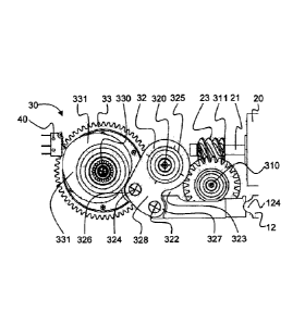
A rotary-leaf/-casement drive 100 according to the
present invention is illustrated in figure 1. Side
elements 53, 54 are provided at the short end sides on
a mounting plate 51 or chassis 51 extending in a
longitudinal direction L (from left to right in figures
CA 02869175 2014-10-01
WO 2013/160087 - 19 -
PCT/EP2013/057239
1-4, 6, 7 and 9-11). A U-shaped cover or casing 52
extending along the chassis 51 can be slid over side
covers 53, 54 and is guided by the side covers 53, 54
when fitted and rests thereagainst in the longitudinal
direction L in the covering position. Here, the chassis
51 and casing 52 are preferably produced from metal and
are preferably each produced integrally. Here, a
substantially closed box is provided, wherein the
casing 52 has a recess 55, formed centrally in the side
faces, in the region of an output shaft 330 of the
rotary-leaf/-casement drive 100. This recess 55 can be
seen in figure 1 on the front side, but can
additionally or alternatively also be provided on the
rear side, depending on requirements. When reference is
made hereinafter to a "shaft", an axis of the shaft is
thus intended at most, depending on the context.
In figure 2, the rotary-leaf/-casement drive 100 is
illustrated from the side without casing 52; a
corresponding view from above is illustrated in figure
3. It is clear from figures 2 and 3 that the following
are arranged adjacently on the chassis 51 in the L-
direction and between the left side cover 53 to the
right side cover 54 (in the box, where the casing is
mounted): (in the first third in relation to L from the
left) a mains connection 56a with a controller 56b and
subsequently a drive module 1.
The drive module 1 extends substantially from the
controller 56b to the right side cover 54 (from a gear
mechanism housing 521, 522 to the motor 20 and to the
energy-store module 112 arranged parallel to and
beneath the motor 20). The left side cover 53
additionally provides feedthroughs in the rotary-leaf/-
casement drive 100 (for example for power lines to the
mains connection 56a and/or data lines or other
connections to the electronics or other components)
and, if need be, operating elements (switches, buttons,
CA 02869175 2014-10-01
WO 2013/160087 - 20 -
PCT/EP2013/057239
touchscreen) or information elements (lamps, LEDs
display).
It can additionally be seen in figure 2 that the drive
module 1 adjoins the controller 56b with the gear
mechanism housing 521, 522 in the L-direction. The gear
mechanism housing 521, 522 surrounds a transmission
gear mechanism 30 (see below) of the drive module 1 and
consists of a first housing shell 521 and a second
housing shell 522, which are joined together from a
direction transverse to L and parallel to the chassis
51 to form a box substantially filling the U-profile of
the cover 52 in cross section. A motor 20 extending
along L engages with an upper region of the gear
mechanism housing from the right in figure 2. The motor
can be actuated via a connection cable 24 by the
controller 56b and can be fastened to the housing 521,
522 via a preferably universal flange 524. A spring
energy module 112 extending along the chassis 51 is
provided parallel to and centrally beneath the motor 20
on the chassis 51 and likewise engages with the gear
mechanism housing 521, 522.
The drive module 1 according to the invention is shown
in figure 4 in a lateral three-dimensional view from
the front from the upper left. The two housing halves
521, 522 can be seen. In addition, round protrusions
521a-c, 522a-b (see also figure 5) can be seen on the
lateral (as considered from the view according to
figure 2) outer face and, on the opposite side of the
same housing halves 521, 522, that is to say internally
in the gear mechanism housing 521, 522, form
indentations for receiving components (for example
bearings of the shafts 310, 320, 330, see below) of the
gear mechanism 30. An indentation 522c for a rotary
transducer at the height of the first shaft 310 is
additionally provided on the outer second housing shell
522, which has an aperture for the passage of the first
CA 02869175 2014-10-01
WO 2013/160087 - 21 -
PCT/EP2013/057239
shaft 310, which is adjoined by the rotary transducer
53 and provides data concerning the rotary position of
the first shaft 310. A gear mechanism 30 with three
axes is also installed; each of the three axes runs
behind a respective one of each of the protrusions.
Here, the protrusion 521a, 522a is advanced into the
gearbox housing interior and thus makes it possible,
via an engagement element, to tap torque from the
output shaft 330 (the third axis beside a screw gear
shaft 310 and an intermediate shaft 320 arranged
centrally between the output shaft 330 and the screw
gear shaft 310, see below) via a latched linkage
connection 333.
The linkage connection 333 (see also figure 15) is an
indentation arranged radially symmetrically about the
output shaft 330 (approximately 1 to 2 cm deep), said
indentation running in a manner widening conically from
the inside out (outer diameter approximately 1,8 cm,
inner diameter at the depth approximately 1,3 cm). The
indentation has 24 teeth running from the inside out
distributed uniformly over the lateral surface of said
indentation (alternatively, 12 to 60 or more teeth may
also be provided) with radial height of 1-2 mm (see
figure 4). The teeth are combs which run on the lateral
surface of the linkage connection 333 in a straight
line from the outside in and toward the axis of the
drive shaft 330.
In this context, reference is now also made to figure
5, which shows the subject matter according to figure 4
from above and from behind. There, it can be seen that
a recess 522a for engagement with a further linkage
connection 333 arranged mirror-symmetrically relative
to the output shaft 330 is also arranged on the rear
side of the housing (that is to say in the housing
shell 522).
CA 02869175 2014-10-01
WO 2013/160087 - 22 -
PCT/EP2013/057239
Due to the detent mechanism of the linkage connection
333 (that is to say by the teeth or combs) according to
figures 4 and 5, an adjustment of the linkage (not
illustrated in the figures) coupled to the
leaf/casement is possible.
Lateral protrusions 523 are provided at the corners of
the box formed by the shells 521, 522 as means for
fastening the box 521, 522 on the chassis 51 and
possibly for the casing 52. Vertically running holes
through these fastening means 523 allow screws, rivets
or similar means to be received, which can then be
screwed or fastened on the chassis 51 or casing 52.
A socket 41 is formed on the left end side of the box
521, 522, via which socket an electric (tactile) switch
40 (see figure 11) fitted in the gear mechanism 30 can
be contacted.
A cylindrical body 20a of the motor 20 can also be seen
in figures 4 and 5. A cylinder axis of this motor body
20a (and therefore also a motor shaft 21, see figure
11) runs parallel to the direction L and advances in
the upper third of the height of the shells 521, 522
through an opening in the rear shell 522 in the gear
mechanism housing 521, 522 for operative connection
with the gear mechanism 30, whereas the motor body 20a
is screwed on a housing flange 524 provided around this
opening. Due to a universal interface between the motor
20 and housing 521, 522, motors of a wide range of
motor sizes and/or different power classes can be used.
Furthermore, the spring module 112 can be seen in
figures 4 and 5. The spring module 112 extends from the
gear mechanism housing 521, 522 toward the right side
cover 54 and rests flat against the housing 521, 522
beneath the motor body 20a via a guide flange 113. The
module 112 comprises the guide flange 113, a spring
CA 02869175 2014-10-01
WO 2013/160087 - 23 -
PCT/EP2013/057239
flange 110, connecting rods 111, a spring 10, a spring
plunger 12 and a spring pressure piece 114.
The four connecting rods 111 are fixed into the corners
on the substantially rectangular guide flange 113
extending in a planar manner via the longitudinal side
thereof transversely over the width of the housing 521,
522 and extend in the direction L as far as the spring
flange 110. At the end sides thereof directed toward
the guide flange 113, the connecting rods 111 have a
threaded bolt for fastening to the housing 521, 522.
The guide flange 113 has corresponding through-holes
for the connecting rods. The guide flange 113 is thus
clamped by the connecting rods 111. In addition, a
preferably circular cylindrical guide 115 is fitted
centrally and in a planar manner on the guide flange
113 and protrudes from the guide flange 113 by
approximately 3 centimeters between the connecting rods
111. The guide 115 is a hollow cylinder (outer diameter
approximately 3 centimeters) with a circular
cylindrical cavity (or a through-hole) of approximately
2.3 centimeters diameter passing through the entire
guide flange 113.
Threaded holes (for example M6) are provided at the end
side on the free end portions of the four connecting
rods 111 of identical length, via which threaded holes
the plate-shaped spring flange 110 (also measuring
approximately 3 centimeters to approximately 5
centimeters) can be screwed on externally. A helical
spring or coil spring 10 is provided between the
connecting bolts 111 and extends from the guide flange
113 in the direction L to the spring flange 110 and is
tensioned therebetween. The spring 10 is the active
element of the energy-store module 112 and is designed
such that it provides up to 5 kilonewtons of spring
energy in order to apply pressure to an eccentric cam
disk 331 (see below and figures 10 and 11).
CA 02869175 2014-10-01
WO 2013/160087 - 24 -
PCT/EP2013/057239
The compression spring 10 is provided at a right end
portion toward the spring flange 110 with the spring
pressure piece 114. The spring pressure piece 114 rests
at the end side from the right on the compression
spring 10 as a plate or disk approximately 4
millimeters thick and covers the compression spring at
the end (in relation to L) substantially preferably in
a flush manner. For improved guidance, a preferably
circular cylindrical portion (diameter approximately 16
millimeters) optionally protrudes centrally and in a
planar manner into the hollow compression spring 10 by
approximately 1 centimeter. In order to be able to
receive the adjusting screw 11, the spring pressure
piece 114 has a cylindrical recess in the form of a
blind bore. Here, this cylindrical portion (together
with the spring pressure piece plate) of the spring
pressure piece 114 preferably provides a recess
approximately 1 centimeter deep (preferably centrally
in relation to a coiled spring cross section) for a
bolt of an adjusting screw 11. This recess is a blind
bore (approximately 8 millimeters in diameter)
approximately 1 centimeter deep, which passes through
the spring compression piece disk into the cylindrical
portion. Here, the adjusting screw 11 is to be guided
laterally without threaded engagement through this
recess, which is preferably circular in cross section,
and is to press on the spring pressure piece 114 when
at the depth of the blind bore and is to press on the
spring pressure piece 114 against the force of the
compression spring 10.
The adjusting screw 11 passes through the spring flange
110 here with threaded engagement (for example M8) from
the outside, contacts the spring pressure piece 114
internally and is received by the recess in the spring
pressure piece 114 as described above. If the adjusting
screw 11 is screwed by means of the threaded engagement
CA 02869175 2014-10-01
WO 2013/160087 - 25 -
PCT/EP2013/057239
so as to project deeper in the spring flange 110, the
adjusting screw 11 passes through said spring flange
110 increasingly deeper and presses the spring
compression piece 114 onto the compression spring 10.
The spring pre-stress thus increases. Such an
adjustment leaves the torque curve (shape thereof)
substantially unchanged. Merely the size (the value) of
the torque is changed in a substantially constant
ratio.
The compression spring 10 is provided at the other end
portion (the left end portion) toward the guide flange
113 with a spring plunger 12. The spring plunger will
now be explained on the basis of figure 13 and figures
6-11. The plunger is to strike or be pushed with a
force up to 5 kilonewtons and is preferably
manufactured from hardened steel (similarly to the
pendulum piece 14, see below).
Figure 13 shows the spring plunger 12 in three-
dimensional view from the side. The plunger body 120 is
cylindrical, preferably circular cylindrical, and
extends from a head portion 122 (with a diameter of
approximately 2 centimeters and a length of
approximately 4 centimeters) to a guide portion 128
(with a diameter of approximately 1.5 centimeters and a
length of approximately 8 centimeters). A disk-shaped
spring stop 127 approximately 2 millimeters thick and
with a diameter of approximately 3 centimeters is
arranged centrally between the head portion 122 and the
guide portion 128. A ring protruding beyond the plunger
body 120 by approximately 5 millimeters with annular
stop faces 121a, 121b (ring faces) arranged
perpendicularly to the longitudinal extension of the
plunger 12 is thus created. The guide portion 128 is
introduced into the cavity of the compression spring
10. To this end, the guide portion can be provided in
the free end region with a plastic sleeve for guidance
CA 02869175 2014-10-01
WO 2013/160087 - 26 -
PCT/EP2013/057239
in the spring. The guide portion 128 widens over a
length over approximately 1 centimeter to a diameter of
16 millimeters toward the stop face 121b on the guide
portion side. This widening ensures that the resilient
end portion is clamped on the widened guide portion 129
directly beside the stop face 121b. Corresponding
sleeves for clamping the plunger 12 can be additionally
or alternatively slid over the guide portion 128
thereof. From the stop face 121a on the head portion
side, the head portion 122 passes via a minimum
undercut 123 (1 millimeter wide and deep) to a press
lug 124 running transversely to the plunger direction
and bordered on either side by a recess 125, 125 in the
form of a partial circular cylinder (cross-sectional
shape is therefore a segment or sector of a circle) of
approximately 5 millimeters circle diameter. To the
front, the press lug 124 is rounded in a circular
manner, such that it has the form of a partial circular
cylinder (preferably with the cross-sectional shape of
a semi-circle) of approximately 5 millimeters circle
diameter arranged transversely to the plunder direction
(see figure 13), and the recesses 125, 126 extend
further toward the plunger body (see figure 13).
Reverting back to figures 4 and 5. The spring plunger
12 fitted on the left end portion of the compression
spring 10 engages via the head portion 122 thereof in
the hollow-cylindrical (and preferably circle-
symmetrical) guide 115 of the guide flange 113 and thus
guides the spring movement linearly, wherein the
pendulum piece 14 is in constant contact from the left
with the press lug 124 and engages from the left with
the guide 115 (wherein the press piece 14
simultaneously pivots upwardly via the left end
thereof, such that an angle of up to 3 degrees and open
to the left relative to the line of action of the
module 112 is created, wherein the pivot point is the
press lug 124, see below). When the stop face 121a
CA 02869175 2014-10-01
WO 2013/160087 - 27 -
PCT/EP2013/057239
contacts the end side of the guide 115, the press lug
124 protrudes by approximately 2-4 millimeters beyond
the guide flange 113 (toward and into the housing 521,
522). The guide 115 is thus used to guide the plunger
12 until the stop face 121a thereof is contacted.
It is additionally clear on the basis of figures 4 and
5 that a hydraulic or other linearly acting energy
store of similar outer dimensions could also be used
instead of the spring energy-store module 112 (or
spring energy-store module 112). It can also be seen
that sufficient space for the installation of different
motor types (with different motor bodies 20a) is
possible.
It can also be seen in figure 5 that a rotary
transducer 530 is fitted on the first axis, that is to
say the screw gear shaft 310. Due to the arrangement of
the rotary transducer 530 on the first stage 310 of the
gear mechanism 30, the corresponding shaft end of the
motor 20 remains freely available for further
applications or functions.
The gear mechanism 30 and cooperation thereof with the
motor 20 and the spring energy store 112 will now be
described on the basis of figures 6-15.
The motor 20 (for example a 100 watt electric motor) is
arranged in the longitudinal direction L and introduces
a shrunk-screw 23 approximately 2.4 centimeters long
into the housing 521, 522 via the motor shaft 21
approximately 5 centimeters long (and measuring
approximately 8 millimeters in diameter). The motor-
side end of the screw 23 is distanced from the motor
body 20a by approximately 2 centimeters.
The screw 23 engages at an incline (that is to say at a
pitch angle) with a screw gear 31 (see figure 9). The
CA 02869175 2014-10-01
WO 2013/160087 - 28 -
PCT/EP2013/057239
screw gear 31 (head circle diameter approximately 5
centimeters, foot circle diameter approximately 4
centimeters, thickness approximately 1 centimeter) is
mounted on the first stage 310 of the three-stage gear
mechanism 30, that is to say the screw gear shaft 310.
The screw gear 311 is preferably manufactured from
plastic for noise reduction. This is possible since the
screw gear is subjected to a lower load than the other
gearwheels (the other gearwheels are preferably solid
and fabricated from metal, in particular from steel).
The screw gear shaft 310 is located, after mounting,
approximately 3.5 centimeters above the chassis 51 and
a good 3 centimeters away from the right end face of
the housing 251, 252 (see the view in figure 4). The
first shaft 310 is actuated by the motor 20 via this
drive connection. The rotary transducer 53 for reading
out the drive function and the rotary position of the
first shaft 310 is fitted on the first shaft 310 to the
rear (see the view according to figure 6), as discussed
above. A smaller, thicker (diameter approximately 1.7
centimeters, thickness approximately 2 centimeters)
gearwheel 312 adjoins the screw gear shaft 310 at the
front (see figure 8).
An axis of the second stage of the gear mechanism 30,
that is to say of the intermediate shaft 320, is
located approximately 4 centimeters lower (as viewed
from the right in figure 4) in the housing 521, 522 and
is placed approximately 18 millimeters higher above the
chassis 51 than the axis of the first stage 310. A
large intermediate gearwheel 321 (see figures 8-10, 14;
not illustrated in figures 6, 7 and 11) is provided on
the intermediate shaft 320 to the front and engages
with the gearwheel 312, whereby the second stage can
then be operated by the motor 20 via the first stage
310. A small intermediate gearwheel 329 (diameter
approximately 4 centimeters, thickness approximately
CA 02869175 2014-10-01
WO 2013/160087 - 29 -
PCT/EP2013/057239
1.2 centimeters) is located to the rear on the
intermediate shaft 320 (approximately 3 centimeters
behind the rearwardly directed side face of the large
intermediate gearwheel 321). A roller lever 32 is
mounted therebetween and is provided as a downwardly
running single lever.
The third stage of the gear mechanism 30 is the output
shaft 330, of which the axis is fastened approximately
5.5 centimeters to the left (in figure 11) and
approximately 5 millimeters beneath the intermediate
shaft 320. The three shafts 310, 320, 330 are mounted
in the corresponding, above-described indentations or
apertures 521a, 522a, 522c (in each case with
corresponding bearings, visible in the figures)
assigned to the round protrusions 521a-c, 522a-c on the
housing side faces internally in the housing 521, 522.
The gear mechanism housing 521, 522 thus forms the
receptacle for the gear mechanism 30 and provides the
mounting of the shafts 310, 320, 330.
The output shaft 330 can be seen in figures 10 and 11.
Figure 15 shows a side view of the output shaft 330. As
can be clearly seen in figure 10, the output gearwheel
33 (thickness approximately 1.2 centimeters, diameter
approximately 8 centimeters) is provided to the rear on
the output shaft 330 (that is to say to the left in
figure 10) after the rear shaft bearing. A switching
ring (or switching cam) 37 and the eccentric cam disk
331 (thickness approximately 1.2 centimeters, radius of
approximately 1.5 centimeters to approximately 3.5
centimeters) then follow to the front, whereupon the
front shaft bearing follows in a manner distanced via a
spacer ring 340.
The switching ring 37 mounted on the output shaft 330
for conjoint rotation therewith is a circumferentially
asymmetrically formed ring (that is to say running with
CA 02869175 2014-10-01
WO 2013/160087 - 30 -
PCT/EP2013/057239
imbalance on the shaft 330), which actuates a cam
switch 42 of a tactile switch 40. Here, the cam switch
42 protrudes between the eccentric cam disk 331 and the
output gearwheel 33 (see figures 9 and 10), is fastened
on a switch 40 and engages the switching ring
circumferentially, contacting the position thereof. The
switch 40 is in turn fastened in the socket 41, as
described above. The system can thus be referenced at
any moment. Due to the arrangement of the corresponding
switching ring 37 on the output shaft, all door
arrangements (linkage systems) can be referenced
cleanly using the same system. As can be seen in
figures 6-8, the output gearwheel 33 meshes with the
small intermediate gearwheel 329 of the intermediate
shaft 320, whereby the third shaft 330 can then also be
actuated (rotated) by the motor 20.
The screw 223 and gearwheels 311, 312, 321, 329, 33,
the switching ring 37, and the eccentric cam disk 331
are each fitted on the corresponding shafts 21, 310,
320, 330 for conjoint rotation therewith, the roller
lever 32 being mounted in a sliding manner.
The roller lever 32 will now be described on the basis
of the exploded illustration of figure 14. The small
intermediate gearwheel 329 is mounted in the end
portion of the intermediate shaft 320 (see above), and
is adjoined by two ball bearings 35, between which a
spacer sleeve 34 is provided, and then the large
intermediate gear 321.
A roller lever limb 328 is mounted on each of the ball
bearings 35 and surrounds the respective ball bearing
and extends downwardly in a planar manner to a
35 roller lever end portion 327 until approximately 5
centimeters below the axis of the output shaft 330. As
can be seen in figure 14, the plate-shaped, flat roller
lever limbs 328, at the edges, each have an end face
CA 02869175 2014-10-01
WO 2013/160087 - 31 -
PCT/EP2013/057239
(to the front in figure 14) running vertically
downwardly in a straight line and, approximately
centrally opposite, a recess 323 protruding laterally
into the lever limbs 328. A circular recess for
receiving a roller axis 322 and a cam-follower roller
axis 324 are formed in the roller lever end portion
327, wherein the cam-follower roller axis 324 is
approximately 5 millimeters above the roller axis 322
in relation to said vertical straight end-face portion.
The roller lever limbs 328 are mounted in a manner
distanced by approximately 1.5 centimeters along the
shaft 320. The roller axis 322 and the cam-follower
roller 326 and a lever hub 325 are located between the
roller lever limbs 328, whereby the two limbs 328 are
connected. The lever hub 325 additionally surrounds the
spacer sleeve 34, through which the shaft 320 passes.
The roller axis 322 and the cam-follower roller axis
324 run parallel to the lever hub 325 between and in
the recesses of the roller lever end portions 327. The
cam-follower roller 326 can be mounted on the cam-
follower roller axis 325 so as to be able to roll,
wherein a rolling surface of the cam-follower roller
326 protrudes to the front beyond said vertical
straight end-face portion and approximately 3
millimeters downwardly. Considered from the side (see
figure 11), the roller lever 32 thus forms an angled
single lever, wherein the cam-follower roller 326 is
fitted in the elbow as viewed to the left, and the
roller 326 in figure 11 protrudes via an angular range
of approximately 250 degrees as viewed substantially to
the left (upwardly and downwardly), wherein the roller
axis 322 is given in the lower right end portion 327 of
the lever 32. It can also be seen in figure 11 that the
roller axis 322 can rotate in or only up to 12
millimeters from the line of action of the energy
spring module 112 toward the output shaft 330 (then,
the cam-follower roller 326 cannot engage any deeper in
CA 02869175 2014-10-01
WO 2013/160087 - 32 -
PCT/EP2013/057239
the eccentric cam disk 331, and the swing upwardly is
limited).
The roller lever 32 thus slides on= the intermediate
shaft 320 and is thus provided in a manner rotatable
thereon and thereabout.
The lever 32 is pressed forward (to the left in figure
11) circumferentially onto the eccentric cam disk 331,
that is to say on the circumferential surface 332
thereof, by the energy-store module 112 rotating about
the intermediate shaft 320 with the cam-follower roller
326. By means of the rolling cam-follower roller 326
pressed on the circumferential-side rolling surface 332
of the eccentric cam disk 331, the pressure applied by
the energy-store unit 112 is thus transmitted to the
output shaft 330, or the torque acting from the
leaf/casement onto the output shaft 330 is transmitted
via pressure application to the helical spring 10.
The eccentric cam disk 331 shown by way of example in
figure 11 is substantially heart-shaped with a rounded
eccentric cam disk tip 335 and is symmetrical. The
shape of the eccentric cam disk 331 determines the
torque curve acting on the output shaft 330 when the
spring 10 is relaxed. Here, all eccentric cam disks
known to a person skilled in the art that cooperate as
intended in terms of pressure with the lever 32 can be
used.
The circle described by the lever 32 with a full
revolution about the intermediate shafts 320 does not
cross the axis of the output shaft 330; the lever 32 is
thus mounted ahead of the output axis, whereby a
compact design of the drive module 1 is made possible.
Due to the arrangement thereof on the intermediate
shaft 320, the lever 32 is formed so as to be short in
such a way that a compact design is achieved.
CA 02869175 2014-10-01
WO 2013/160087 - 33 -
PCT/EP2013/057239
As illustrated in figure 11 and described above, the
roller lever 32 provides the roller axis 322 from the
left, and the plunger 12 provides the press lug 124
from the right. The roller axis 322 and press lug 124
are brought into operative connection by the rigid
pendulum piece 14.
The pendulum piece 14 is illustrated in figure 12 and
can be seen in figures 6-11. The pendulum piece 14
consists of a substantially elongate pendulum body 140
with a cross-sectional shape which, centrally, is
substantially U-shaped (rectangular with a recess 141).
Side walls 149 are formed by the recess 141 and are
approximately 4 millimeters thick. The side walls 149
are connected centrally of the pendulum piece 14 via a
flat base surface, which is approximately 2 to 3
millimeters thick, approximately 12 millimeters wide
and just under 2 centimeters long. As can be seen in
figure 12, the recess 141 extends upwardly over almost
the entire length of the pendulum piece 14, which is
just under 8.5 centimeters, and runs downwardly. In the
lateral lower edge region of the recess 141 (that is to
say as viewed to the left/right in figure 12 in cross
section), the recess is in each case rounded with
rounding radii from approximately 2.5 to 5 centimeters,
in particular of 3.2 centimeters (the circle midpoints
are in each case located above the straight central
base surface of the pendulum piece 14).
The pendulum piece 14, in longitudinal extension, has a
left end portion (a roller lever receiving portion 143)
and a right end portion (a plunger receiving portion
142) (see figure 12). Here, the recess 141 extends as
far as these end portions 142, 143 (see figure 12). In
particular, the recess 141 receives an upper part of
the plunger receiving portion 142 (see recess 141a in
figure 12). This is advantageous so that, when the
CA 02869175 2014-10-01
WO 2013/160087 - 34 -
PCT/EP2013/057239
plunger receiving portion 142 engages with the guide
115 of the guide flange by approximately 1 to 2
centimeters, a simultaneous bend movement (or a swing
movement) is possible upwardly in an unimpeded manner
(see below). The pendular movement is to be
approximately up to 3 degrees here, and the pivot point
is the press lug 124, that is to say the pendulum piece
14 is pivoted upwardly via the left end thereof from
the horizontal line of action of the energy-store
module 112.
The roller lever receiving portion 143 is tapered on
either side symmetrically and gradually over the width
from approximately 20 millimeters to approximately 14
millimeters as viewed from above over a length of
approximately 1 to 1.5 centimeters as viewed from the
outer edge, whereby edges 148 running over the side
faces 149 are formed externally. These edges 148 each
run from top to bottom and form a partially circular
recess 148a (circle segment with radius of
approximately 1 centimeter) toward the pendulum body
140, wherein the circle midpoint of a circle forming
the circle segments lies in the center of a further
recess 147. The edges 148 are each rounded at the top
and bottom (see figure 12).
The recess 147 protrudes centrally at the end by
approximately 8.5 millimeters into the cuboidal and
narrowed roller lever receiving portion 143 and is
continuous from the front to the rear (see figure 12),
such that the roller lever receiving portion 143 is
fork-shaped, that is to Say has a projection 143a at
the top and at the bottom. In a lateral plan view, the
recess 147 runs in a U-shaped manner, has a clear width
of approximately 1.1 centimeters between the portions
143a, and is provided in a manner rounded in the depth
(semi-circularly) with a radius with approximately 5.5
millimeters. This recess 147 corresponds as a circular
CA 02869175 2014-10-01
WO 2013/160087 - 35 -
PCT/EP2013/057239
cylindrical overlap with the circular cylindrical
roller axis 322 (see also figure 10), which is received
therein. The step-like narrowing of the width of the
roller lever receiving portion 143 serves for
engagement between the roller levers 328 distanced by
approximately 1.5 centimeters (see figure 10), whereas
the round roller lever end portions 327 engage with the
recess 148a at a distance (approximately 1 millimeter)
from the edge face 148. The significance of the recess
328 is now also clear on the basis of figure 11, since
the pendulum piece 14 needs this space 323 for the
intended pendular movement.
The roller lever 32 thus engages off-axis with the
recess 147 in the pendulum piece 14 in a manner coupled
via the roller axis 322 thereof.
The plunger receiving portion 142 extends substantially
cylindrically (approximately 19 millimeters diameter)
centrally from the right end face of the pendulum piece
14 over approximately 18 millimeters toward the
pendulum body 140 (see figure 12). In particular, the
plunger receiving portion 142 should also be able to
engage with the guide 115 of the energy-store module
112, more specifically from the other side compared
with the plunger 12 and, in doing so, should still be
able to perform the intended pendular movement thereof.
The cross section is thus identical to that of the
plunger head portion 122 or is to be selected slightly
smaller. A cylindrical recess 144 with circle segment-
shaped recess (radius approximately 5 millimeters, see
figure 12) runs from the rear to the front centrally in
the right end face of the plunger receiving portion
142. This groove 144 is approximately 2 millimeters
deep (runs transversely to L and horizontally) and
corresponds as circular cylindrical overlap with the
circular cylindrical press lug 124 of the plunger 12
(see figure 11). Circle segment-shaped flat end face
CA 02869175 2014-10-01
WO 2013/160087 - 36 -
PCT/EP2013/057239
portions 145 and 146 can be seen in figure 12 and are
arranged opposite the recesses 125, 126 in the
assembled state and engage with said recesses when the
pendulum piece 14 performs the intended pendular
movement thereof. The pendulum piece 14 may thus
simultaneously perform a linear movement (in the
horizontal by approximately 1 centimeter to 2
centimeters) and an angular movement or pendular
movement (in the horizontal over the entire length of
the pendulum piece 14 for example by 1 millimeter to 10
millimeters, preferably 1 millimeter to 5 millimeters).
The pendular movement from the horizontal is
approximately up to 3 degrees in this case.
The coupling of the pendulum piece 14 can also be
produced in an alternative embodiment on one side or
two sides by a spherical overlap and a spherical
engagement element instead of, as described above, by a
circular cylindrical overlap 144, 147 and a circular
cylindrical engagement element 124, 322 or by a
coupling with an axis.
As viewed from below (see figure 7), the pendulum piece
14 runs over the length thereof of approximately 85
millimeters between the large intermediate gearwheel
321 and the small intermediate gearwheel 329 and
contacts the roller lever 32 and the plunger 12
directly. As viewed from below (see figure V), a
straight, direct line of action between the spring 10
and the eccentric cam disk 321 is thus provided. As
viewed from the side (see figure 11), this operative
connection is such that the plunger 12 acts via the
press lug 124 in the line of action of the energy-store
module 112. This line of action runs parallel to the
longitudinal extension of the motor 20 and energy-store
module 112, wherein the motor 20 and the energy-store
module 112 in relation to the intermediate shaft 320
and in relation to the gear mechanism 30 are arranged
CA 02869175 2014-10-01
WO 2013/160087 - 37 -
PCT/EP2013/057239
spatially on the same side. In addition, the line of
action of the energy-store module 112 runs in a
straight line beneath and through the screw shaft 310,
the intermediate shaft 320 and the output shaft 330.
The operative connection between the energy-store
module 112 and the output shaft 330 is then redirected
via the press lug 124 received in the recess 144 and
moving horizontally in a straight line to the pendulum
piece 14 movable in a straight line and transversely
thereto and mounted in a manner suitable for pendular
motion vertically to the chassis 51 and is then
redirected again to the roller axis 32 received in the
recess 147 in the circular movement of the roller lever
32 and is directed upwardly via the roller 326 to the
eccentric cam disk 331 and therefore to the output
shaft 330. Here, the pendulum piece 14 swings depending
on the arrangement of the intermediate shaft 320 and
the length of the roller lever 32. If the roller axis
322 reaches from the intermediate shaft 320 at most to
the line of action of the energy-store module, the
pendulum piece 14 thus always swings upwardly from this
line of action (horizontally from the press lug 124 to
the left in figure 11) toward the output shaft 330.
However, the roller lever 32 may also be 1 to
approximately 5 millimeters longer, and can reach the
roller axis 322 at the bottom point (maximum deflection
downwardly in figure 11) over the line of action of the
energy-store module. The pendulum piece 14 then swings
downwardly over this line of action by 1 to
approximately 5 millimeters.
In an alternative embodiment compared with figure 11,
the axis of the roller axis 322 with maximum
displacement of the pendulum piece 14 to the left
(maximally relieved spring 10) may also lie directly
vertically below the axis of the intermediate shaft
320.
CA 02869175 2014-10-01
WO 2013/160087 - 38 -
PCT/EP2013/057239
Generally, the pendular movement of the pendulum piece
14 can be determined by the cooperation between length
of the roller lever 32 or position of the intermediate
shaft 320 and position of the coupling point between
pendulum piece 14 and roller axis 322. If, for example,
the distance between the axis of the roller axis 322
and the intermediate shaft 320 is exactly the same size
as the vertical distance between the axis of the
intermediate shaft 320 and the line of action of the
energy-store module 112, the angle between the axis of
the intermediate shaft 320 and the axis of the roller
axis 322 and the line of action may thus also enclose
90 degrees without the pendulum piece 14 swinging
downwardly over said line of action. If the axis of the
intermediate shaft 320 is closer to the line of action,
the intermediate shaft 320 can thus be displaced to the
left by way of example (in figure 11), such that the
angle just described always remains greater than 90
degrees and the pendulum piece 14 therefore does not
swing downwardly over said line of action.
As intended, only pendular movements of the pendulum
piece 14 upwardly (toward the intermediate shaft 320
and possibly the output shaft 330, if this does not lie
on the line of action of the energy-store module) are
therefore implemented, which allows a particularly
compact design.
The movement of the drive module 1 can thus be
summarized as follows:
When the motor 20 rotates the shaft 21 thereof, the
screw 23 then engages with the screw gear 311,
whereupon the first shaft 310 rotates the gearwheel
312. The gearwheel 312 engages with the large
intermediate gearwheel 321, whereupon the second shaft
320 rotates with the small intermediate gearwheel 329
(without actuating the sliding lever 32). The small
CA 02869175 2014-10-01
WO 2013/160087 - 39 -
PCT/EP2013/057239
intermediate gearwheel 329 engages with the output
gearwheel 33, whereby the third shaft 330 rotates with
the eccentric cam disk 331 connected thereto for
conjoint rotation therewith.
The rotating eccentric cam disk 331 then actuates the
roller lever 32 on account of the changing center
distance between the rolling surface 332 of the
eccentric cam disk 331 and the axis of the output shaft
330 via the cam-follower roller 326 pressed against the
rolling surface 332. The rotating roller lever 32 acts
via the roller axis 322 thereof on the pendulum piece
14 coupled to said roller axis 322 in an off-axis
manner under spring pressure with the circular
cylindrical overlap 147 at the proximal pendulum piece
end. The pendulum piece 14 acts, with the circular
cylindrical overlap 144 at the distal pendulum piece
end, on the press lug 124 of the plunger 12 coupled in
an off-axis manner under spring pressure so as to
engage with the overlap 144, said plunger 12 then
acting linearly on the spring 10. An operative
connection between the output shaft 330 and spring
energy store 112 is thus produced.
In an alternative embodiment, the motor 20 engages the
output gearwheel 33 or a gearwheel of the intermediate
shaft 320 directly (for example via a screw or a bevel
gear). If a transmission gear mechanism from the motor
to the output shaft is provided without use of the
intermediate shaft, the intermediate shaft is thus
provided substantially only for the roller lever 32.
A preferred clamping piece 60 having a lever 700 and a
stop element 70 will now be described with reference to
figures 16-18.
Figure 16, in a side view, shows the gear mechanism
housing 521, 522 mounted on the chassis 51. It can be
CA 02869175 2014-10-01
WO 2013/160087 - 40 -
PCT/EP2013/057239
seen that the substantially cylindrical clamping
element 60 according to figure 18 is used in the
linkage connection 333 (hidden in figure 6, but see
figure 4 for example) and protrudes laterally beyond
the gear mechanism housing 521, 522. A lever 700 with a
stop finger 708 is provided on the clamping piece 60
mounted rotatably in the linkage connection 333 of the
output shaft 330 for conjoint rotation with said
clamping piece 60 and cooperates with the stop element
70 according to figure 17 and in particular limits the
movement of the output shaft 330. As the output axis
330 rotates, the stop finger 708 describes a circular
path.
Figure 17 shows the construction of the stop element 70
according to figure 16. A screw 71 (for example M6)
passes through a substantially cylindrical stop cam 72
through a non-central hole 71a. The screw 71 also
passes through a damping element 73 in the form of a
hollow cylinder, a stop ring 74, a preferably centrally
drilled stop disk 75, and is in fixed threaded
engagement with a threaded hole 84 in a bar-shaped stop
support 80. A screw head of the screw 71 then clamps
the stop cam 72 and thus the further elements 73, 74,
75 detachably on the stop support 80. The stop element
70 is then rotatable once the screw 71 has been
slightly loosened and can be clamped again in another
position.
Here, the stop cam 72 is a disk approximately 2
millimeters to 5 millimeters thick with a diameter of
approximately 3 centimeters. A center of the hole 71a
is radially offset outwardly by approximately 1 to 5
millimeters from the disk center and is provided on the
outer face (visible in figures 16 and 17) with a
countersink for the screw head. Due to this offset of
the hole 71a relative to a center of the disk, the stop
point for the stop finger 708 can be shifted
CA 02869175 2014-10-01
WO 2013/160087 - 41 -
PCT/EP2013/057239
circumferentially on the effective circle of the stop
finger 708 when the screw 71 has been loosened.
A cylinder with an outer diameter of approximately 2
centimeters protrudes centrally on the opposite side of
this disk, the hole 71a passing through said cylinder.
The hollow-cylindrical damping element 73 preferably
made of rubber is then slid onto this cylinder. The
stop ring 74 is then slid onto this damping element 73,
preferably with an accurate fit (outer diameter
approximately 3.2 to 3.5 centimeters, such that it
protrudes beyond the disk of the cam element). The stop
ring 74 provides the lateral stop face for the stop
finger 708 protruding from the gear mechanism housing
521, 522. Here, the stop finger 708 can be curved
slightly outwardly laterally in the stop region. The
stop ring 74 is damped with respect to lateral contact
by the damping element 73. The stop support 80 is then
contacted via a downwardly flattened (circle segment-
shaped recess, see figure 17) stop disk 75 drilled
centrally for the screw 71 and measuring approximately
1 to 4 millimeters thick and approximately 3
centimeters in diameter. The flattened side of this
disk 75 contacts the chassis 51 in a planar manner. The
screw 71 is screwed tightly in a threaded hole 84 in
the stop support 80. A person skilled in the art knows
to place the holes 84 in the stop support 80 in
accordance with requirements imposed by the situation
in question, such that the screw 71 is attached, for
example in accordance with figure 16, beneath the
output shaft 330 in a manner offset for example by 1 to
8 millimeters to the left in relation to the axis
thereof (see figure 16).
The stop support 80 is a bar approximately 14
centimeters long of rectangular cross-sectional shape
(approximately 1 centimeter by 2 centimeters), which is
screwed via a narrow long side onto the chassis 51 (see
CA 02869175 2014-10-01
WO 2013/160087 - 42 -
PCT/EP2013/057239
figure 16). To this end, holes 82 are provided in the
stop support 80, and screws 81 can be inserted into
said holes so as to fix the support 80 on the chassis.
The stop support 80 extends along the gear mechanism
housing 521, 522 and is placed between the fastening
means 523 of the gear mechanism housing 521, 522 and
has recesses 83 in the lower lateral end regions in
order to receive the fastening means 523. The support
80 and the gear mechanism housing 521, 522 are thus
screwed tightly on the chassis 51.
The stop support 80 comprises the holes 84
approximately centrally relative to the height of the
front side of said stop support, wherein two laterally
spaced holes 84 (for example M6) are provided in such a
way that the same support can be used on the front side
(housing part 521) and on the rear side (housing part
522). This is advantageous since the output shaft 330
is not located centrally relative the fastening means
523.
The stop element 70 fastened in such a way on the stop
support 80 can now be rotated with loosened screw 71,
wherein the stop face of the stop ring 74 can be
displaced continuously circumferentially with respect
to the effective circle of the stop finger 708 thanks
to the eccentric construction. A fine adjustment of the
stop position is thus provided.
In addition, figure 17 to the right shows the lever
700, which will now be described together with the
clamping piece 60 according to figure 18. The clamping
piece 60 transmits the torque from the output shaft 300
to the linkage (not illustrated in the figures) for
actuation of the corresponding leaf/casement. The
clamping piece 60 has a substantially cylindrical main
body 62 (diameter approximately 3 centimeters, length
approximately 5 centimeters), which extends from an
CA 02869175 2014-10-01
WO 2013/160087 - 43 -
PCT/E22013/057239
engagement portion 67 to a connection element 63. A
cylinder axis of the main body 62 runs identically with
the axis of rotation of the output shaft 330 when the
clamping piece 60 is inserted into the linkage
connection 333.
The engagement portion 67 is formed conically and
concentrically about the cylinder axis and has 8 combs
or teeth 68, which run along the cylinder axis over the
lateral surface of the engagement portion 67. The
engagement portion 67 is formed in a manner
complementary to the conically formed and furrowed
linkage connection 333 for form-fitting engagement.
The linkage connection 333 has three times as many
teeth, specifically 24 in number. The teeth 68 of the
engagement element 67 then engage via the tips thereof
with the substantially triangular recess between the
teeth of the linkage connection 333. The clamping
element 60 can thus be inserted into the linkage
connection 333 in a manner rotated about the cylinder
axis of the clamping element by 15 degrees (or integer
multiples thereof) from an insert position. In order to
fasten the clamping piece 60 in the linkage connection
333, the clamping piece 60 has a longitudinal bore 61,
into which a screw for clamping the clamping piece in
the linkage connection 333 can be inserted.
A toothing 64 comprising 35 individual teeth 65
approximately 1.8 millimeters high protrudes laterally
circumferentially on the main body 62 approximately
centrally with respect to the length of the main body
62. These teeth are approximately 2 millimeters high
and extend over the lateral surface of the main body 62
approximately 7 millimeters along the cylinder axis of
the main body 62.
CA 02869175 2014-10-01
WO 2013/160087 - 44 -
PCT/EP2013/057239
The cylindrical connection portion, which on the end
face provides a convex recess 69 (approximately semi-
circular segment-shaped with a circle diameter of 1.6
centimeters) for receiving the linkage is provided at
the end face on the cylindrical main body 62 on the
side of the clamping piece 60 opposite the engagement
portion 67 (see figures 16 and 18).
The lever 700 to the right in figure 17 is
approximately 6 centimeters long in total and
approximately 3 centimeters wide at the front and
approximately 8 millimeters thick. It has a lever ring
702 with a recess 701. The lever ring 701 comprises the
main body 62 of the clamping piece 60 (see figure 16),
wherein the recess 701, through which the clamping
piece 60 is guided, has a toothing 703, which
corresponds in a complementary manner to the toothing
64 of the clamping piece 60 as a spline. The stop
finger 708 protruding laterally on one side has a
radially running slit 706 that is continuous to the
recess 701 and to the outside (see figure 16). This
slit 706 is approximately 2 to 3 millimeters wide. A
bore 705 running transversely to the slit 706 is
provided on the lateral narrow side on the stop finger
708. A screw 704 (for example M4) is introduced
laterally into the lever 700 through this bore 705 and
is present externally on the lever 700 with a screw
head and passes via the slit 706 into the opposite part
of the stop finger 708 and is in threaded engagement
therewith. By tightening the screw 705 the slit 706 is
narrowed and a diameter of the recess 70 reduces. The
lever 700 can therefore be clamped on the main body 62
for conjoint rotation therewith and in a form-fitting
manner.
The linkage and the clamping piece 60 are fixed or
clamped to the output shaft 330 by a further screw. The
linkage and the clamping piece 60 have a bore 61 of
CA 02869175 2014-10-01
WO 2013/160087 - 45 -
PCT/EP2013/057239
corresponding size (approximately 8 millimeters in
diameter) parallel to the cylinder axis of the main
body 62 in order to pass through the screw. Since the
torque is transmitted in a form-fitting manner (conical
spline) from the output shaft 330 to the clamping piece
60 and further to the linkage, and since the screw only
clamps the element, the screw is ideally also only
subject to tensile load.
As can be seen in figure 16, the stop element 70 can
now be released via the screw 71 and rotated, for
example 5 to 20 degrees, wherein the stop point of the
stop finger 708 is then displaced continuously upwardly
or downwardly. The stop point along the effective
circle of the stop finger 708 is therefore displaced.
An extreme angle of aperture of the leaf/casement can
thus be adjusted roughly via the toothing 64, 703, and
the fine adjustment can be achieved continuously by
corresponding rotation of the stop element 70.
_
CA 02869175 2014-10-01
WO 2013/160087 - 46 - PCT/EP2013/057239
List of reference signs
1 drive module 145,146 end face
compression spring 147 recess
100 door drive 148 edge
11 adjustment screw 148a recess
110 spring flange 149 side wall
111 connection rods
112 spring energy- 20 motor
store module 20a motor body
113 guide flange 21 motor shaft
114 spring press piece 23 screw
115 hollow-cylindrical 24 connection
guide cable
12 spring plunger 30 gear mechanism
120 plunger body
121a,121b stop faces 310 screw gear
122 plunger head shaft
portion 311 screw gear
123 undercut 312 gearwheel
124 press lug
125,126 recess 32 roller lever
127 spring stop 320 intermediate
128 guide portion shaft
321 large
14 pendulum piece intermediate
140 pendulum piece gearwheel
body 322 roller axis
141 longitudinal 323 recess
recess 324 cam-follower
141a recess roller axis
142 plunger receiving 325 lever hub
portion 326 cam-follower
143 roller lever roller
receiver portion 327 roller lever
144 recess end portion
CA 02869175 2014-10-01
WO 2013/160087 - 47 - PCT/EP2013/057239
328 roller lever limb 56a mains device
329 small intermediate 56b controller
gearwheel 60 clamping piece
61 bore
33 output gearwheel 62 main body
330 output shaft 63 connection portion
331 eccentric cam disk 64 toothing
332 rolling surface 65 tooth
333 conical linkage 67 engagement portion
connection 68 toothing
335 eccentric cam disk 69 recess
tip
34,340 spacer sleeve 70 stop element
35 sliding bearing 71 screw
36 feather key 71a bore
40 electric switch 72 stop cam
41 socket 73 damping
42 switching lug 74 stop ring
75 stop disk
51 chassis
52 casing 700 lever
521 first housing 701 recess
shell 702 lever ring
521a opening for output 703 toothing
shaft 704 screw
522 second housing 705 bore
shell 706 slit
522a opening for output 708 stop finger
shaft
523 fastening means 80 stop support
524 housing flange 81 screw
53,54 side element 82 bore
530 rotary transducer 83 recess
55 recess 84 bore