Note: Descriptions are shown in the official language in which they were submitted.
õ
MOLTEN SALT NUCLEAR REACTOR
[0001] [This paragraph is left blank intentionally.]
FIELD
[0002] The present disclosure relates generally to nuclear reactors. More
particularly,
the present disclosure relates to molten salt nuclear reactors.
BACKGROUND
[0003] Molten Salt Nuclear reactors have been proposed in several
different forms
but two main areas differentiate their use. First is how the fissile and
fertile materials are
carried. Second is whether extra moderator is employed (graphite is typically
specified).
The first factor sees three potential designs, which are described below.
[0004] Single Fluid reactor design: One single salt that contains both
fertile (e.g.,
thorium and/or U238) and fissile material (e.g., U233 and/or Pu239, U235 etc).
The benefit
of this mode of operation is that typically, the core design is quite simple.
The drawbacks
include: (1) difficult fission product removal chemistry (as thorium is
chemically virtually
identical to rare earth fission products) and (2) possibility of a large
leakage of neutrons
which both lowers the potential breeding ratio and may cause neutron induced
damage on
the reactor vessel. Examples of single fluid reactors include the post 1968
Molten Salt
Breeder Reactor (MSBR) of Oak Ridge National Laboratories (ORNL) and MOSART of
Russia.
[0005] Two Fluid reactor design: There are separate carrier salts for the
fertile
(typically thorium) and fissile material (typically U233). The two main
benefits are simpler
fission product removal chemistry and greatly reduced leakage of neutrons
since they are
absorbed in the surrounding fertile blanket. The main drawbacks are: (1) a
potentially more
complex core, (2) the need for a barrier material between the two salts that
can retain
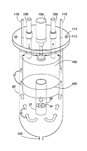
strength in a strong neutron flux, and (3) somewhat decreased proliferation
resistance
understood by those trained in the field since a "blanket÷ is employed. As an
example, a two
fluid reactor design was studied by ORNL from 1960 to 1968.
[0006] 1 and 'A Fluid reactor design (one and a half fluid reactor
design): A hybrid
design in which a central fuel salt containing both fertile and fissile
material is surrounded
- 1 -
CA 2869561 2018-07-17
CA 02869561 2014-10-03
WO 2012/135957
1PCT/CA2012/050218?1 8
by a fertile only blanket salt. This has the advantage of decreased leakage of
neutrons
but fission product removal remains difficult and there is still a barrier
material needed
between the central region and the blanket region, albeit potentially in a
weaker neutron
flux than the Two Fluid design. There is also the blanket salt proliferation
issue.
Examples include ORNL 1954 to 1960, and the French TMSR/MSFR 2005 to present.
[0007] In the prior art, the use of a bulk moderator throughout the
core (neutron
moderator material formed throughout the volume of the nuclear core) can
affect reactor
design in many ways. Graphite has been by far the most commonly proposed
moderator
in the core but clad beryllium and/or heavy water has also been investigated.
The main
effect of having a moderator is a softening of the neutron spectrum, which can
allow
operation with far less fissile material. A second very important ability
enabled by the use
of bulk moderator is that it limits neutron leakage by a method referred to as
an under
moderated outer zone, which is described below.
[0008] A Single Fluid design has the drawback that significant numbers
of
.. neutrons can be lost to leakage and these same neutrons can damage the
outer vessel
(typically a nickel alloy such as Hastelloy N). Adding reflector material
between the core
and vessel wall (i.e., adding a graphite lining to the vessel wall) has only a
limited effect
as would be understood by workers in the field.
[0009] With graphite or other moderator throughout the core, Oak Ridge
National
Labs proposed an under moderated outer zone in the mid 1960s. They first
calculated
the ideal ratio of fuel salt to graphite for an infinite core (i.e., no worry
of leakage). This
led to a specific neutron spectrum, softened by the graphite, which implies
that a
particular ratio of fertile (typically thorium) to fissile (typically U233)
will make the reactor
critical. This salt to graphite ratio (typically about 13% salt in most ORNL
work) is
employed only for the central core. In a thin outer zone (typically about a
meter or less in
thickness) they used a much higher ratio of salt to graphite (37% in ORNL
work). This
results in a harder neutron spectrum in this zone and, as would be understood
by workers
in the field, leads to a much greater absorption of neutrons in the fertile
(thorium) versus
production in fissile (U233). For an example, see Nuclear Applications &
Technology,
Vol. 8, February 1970, page 210, Fig. 1. In reactor physics terms this means
the inner
core has a K infinity of greater than one (net producers of neutrons) while
the outer zone
has K infinity much less than one (net absorber). The overall combination is a
K effective
of just over 1.0 as required to maintain criticality.
- 2 -
CA 02869561 2014-10-03
WO 2012/135957
1PCT/CA2012/050218?1 8
[0010] Three cases relating to an unreflected core, a reflected core
and a core
with an under moderated outer zone core are shown in Figures 1 and 2, which
are meant
only to show differences in neutron flux profiles for different types of
single fluid reactors.
In Figure 1, plot 1 shows the neutron flux for a single fluid molten salt
nuclear core being
free of any neutron reflector at the periphery of the nuclear core vessel
(i.e., in the
absence of reflector 4), and plot 2 shows the neutron flux for a nuclear core
having a 40
cm-thick neutron reflector 4 at the periphery of the nuclear core vessel. Also
shown at
Figure 1 is a wall 3 of the reflector 4. Figure 2 shows a neutron flux plot 5
(neutron flux
profile) for a single fluid molten salt reactor core without a reflector but
with an under
moderated outer zone 6. As shown in Figure 2, the neutron flux at the outer
periphery
(-200 cm) is greatly reduced in comparison to the unreflected "bare core" plot
1 of Figure
1.
[0011] There are significant drawbacks to using bulk graphite or other
moderators
(clad beryllium, heavy water). For example, graphite is known to have a
limited lifetime in
the core which has forced designers to either propose very low power density
and thus
very large cores or to plan for periodic graphite replacement which is a
difficult challenge.
As well, the overall safety of Molten Salt Reactors is outstanding but the
potential fire
hazard of graphite cannot be ignored. Finally graphite use represents a
significant
disposal. With clad beryllium used throughout the core, the losses of neutrons
to the
cladding are excessive.
[0012] Thus it has long been a desire to be able to design a practical
Single Fluid
reactor that does not employ bulk moderators such as graphite. However,
without an
under moderated outer zone, the issue of neutron leakage and damage to the
outer
vessel have always curtailed these efforts. As well, the less moderated
neutron spectrum
means a shorter prompt neutron lifetime which has negative implications on
reactor
control as would be known by those trained in the field. As an example, in the
MOSART
design of Russia which is a Single Fluid transuranic waste burner, they felt
the need to
propose two thick layers, a layer of graphite facing the salt to slow neutrons
down and
reflect some neutrons and then of steel blocks to absorb the unreflected
neutrons. This
20 tonne liner of graphite would still require periodic replacement which
limits the design's
utility. Finally, as would be known by those trained in the art, a graphite
reflector can in
many cases actually increase the overall leakage of neutrons due to a fission
power
peaking from more thermalized neutrons re-entering the core salt from the
graphite
reflector.
[0013] Therefore, improvements in molten salt nuclear reactors are
desirable.
- 3 -
CA 02869561 2014-10-03
WO 2012/135957
1PCT/CA2012/050218?1 8
SUMMARY
[0014] In a first aspect, the present disclosure provides a single
fluid molten salt
nuclear reactor that comprises: a vessel having a central region and a vessel
wall; a
support structure; a neutron moderator secured to the support structure and
located in the
central region of the vessel, the neutron moderator having at least one
through hole
defined therein; and a pump to circulate a molten salt in the vessel, the
support structure,
the neutron moderator, and the pump being arranged to circulate the molten
salt through
the at least one through hole of the neutron moderator and between the neutron
moderator and the vessel wall.
[0015] In a second aspect, the present disclosure provides a single fluid
molten
salt nuclear reactor that comprises: a vessel having a central region and a
vessel wall;
two opposite walls disposed at opposite ends of the vessel; a support
structure; a neutron
moderator secured to the support structure and located in the central region
of the vessel;
a molten salt inlet formed on one of the two opposite walls; a molten outlet
formed on the
other of the two opposite walls; and a pump operationally connected to the
molten salt
inlet and to the molten salt outlet, the pump to circulate a molten salt in
the vessel.
[0016] Other aspects and features of the present disclosure will
become apparent
to those ordinarily skilled in the art upon review of the following
description of specific
embodiments in conjunction with the accompanying figures.
BRIEF DESCRIPTION OF THE DRAWINGS
[0017] Embodiments of the present disclosure will now be described, by
way of
example only, with reference to the attached Figures.
[0018] Figure 1 shows plots of neutron flux as a function of distance
from the
core for a reflected core and for an unreflected core.
[0019] Figure 2 shows a plot of neutron flux as a function of distance from
the
core for a reactor having an under-moderated zone.
[0020] Figure 3 shows plots of neutron flux as a function of distance
form the
core for a molten salt nuclear reactor having a moderated central zone and for
the same
molten salt nuclear reactor without the moderated zone.
[0021] Figure 4 shows a generalized embodiment of a Single Fluid Molten
Salt
Nuclear Reactor of the present disclosure.
[0022] Figure 5 shows an embodiment of a Single Fluid Molten Salt
Nuclear
Reactor of the present disclosure that includes a support structure.
- 4 -
CA 02869561 2014-10-03
WO 2012/135957
1PCT/CA2012/050218?1 8
[0023] Figure 6 shows an embodiment of a Single Fluid Molten Salt
Nuclear
Reactor of the present disclosure that includes a salt flow guide structure.
[0024] Figure 7 shows another embodiment of a Single Fluid Molten Salt
Nuclear
Reactor of the present disclosure.
[0025] Figure 8 shows yet another embodiment of a Single Fluid Molten Salt
Nuclear Reactor of the present disclosure.
[0026] Figure 9 shows atop down view of an embodiment of the present
disclosure used in modeling.
[0027] Figure 10 shows a side view of the embodiment of Figure 9.
[0028] Figure 11 shows a top down view of the central core shown at Figure
9.
[0029] Figure 12 shows plots of relative neutron flux as a function of
energy.
DETAILED DESCRIPTION
[0030] The present disclosure provides an improved Single Fluid Molten
Salt
Nuclear Reactor (also referred to as a Single Fluid Reactor). In some
embodiments, the
core diameter of the Single Fluid Reactor can range from 2 to 4 meters. The
Single Fluid
Reactor has an inner zone that includes a solid neutron moderator, which can
have salt
coolant channels (through holes) defined therein. In some embodiments, the
solid
neutron moderator can be replaced when required. This solid neutron moderator
can
have a relatively small diameter, which can range, in some embodiments, from
less than
one meter to about 1.5 meter. The solid neutron moderator effectively creates
an inner
zone with a neutron spectrum (profile) that is far more thermalized than if
the solid
neutron moderator were absent. The surrounding layer of salt surrounding this
modest
sized inner zone (the inner zone can also be referred to as a central zone)
will have a
much harder neutron spectrum. The inner zone to which the present disclosure
refers is
the volume of the solid neutron moderator plus the volume of any through holes
or
apertures defined by the solid neutron moderator. By choosing a single fuel
salt with an
appropriate ratio of fertile (e.g., thorium or U238) to fissile (e.g., U233,
U235, or Pu) one
can assure that the inner zone has a k infinity of much greater than 1.0 and
the outer
layer of pure salt a K infinity of less than 1.0, and that overall the k
effective is the needed
value of just over 1.0 as would be understood by a worker skilled in the art.
[0031] Figure 3 shows two plots of the neutron flux fora Single Fluid
Reactor.
Plot 7, labeled "no central zone", is when no central moderated zone (no
neutron
moderator at the central region) is present in the Single Fluid Reactor. As
shown by plot
- 5 -
CA 02869561 2014-10-03
WO 2012/135957
1PCT/CA2012/050218?1 8
7, in this situation there is still significant neutron flux at the outer edge
of the core which
is the vessel wall 8. The neutron flux at the wall 8 can lead to potential
damage and to
loss of neutrons to leakage. Plot 9, labeled "Two Zone Profile", is with the
central
moderated zone 10 present and, as the outer zone (the zone outside the
moderated zone
10) is under-moderated this leads to a much more rapid decline in the neutron
flux and
effectively a much lower neutron flux at the outer vessel wall. Plot 9 shows
that a Single
Fluid Reactor, in accordance with the present disclosure, can lead to
significantly less
damage at the wall 8 of the vessel containing the fuel salt.
[0032] Figure 4 shows a generalized depiction of an embodiment of a
Single
Fluid Reactor of the present disclosure. The Single Fluid Reactor includes an
outer
vessel 20, a central moderator 22 that defines through holes 24 (salt
channels) to allow
passage of molten salt (fertile/fissile salt) therethrough. The molten salt
traverses the
channels 24 in the direction of the arrow 26. The volume comprised between the
central
moderator 22 and the outer vessel 20 includes a salt zone 28, free of bulk
solid
moderator, in which the fissile/fertile salt also flows in the direction of
the arrow 26. For
clarity purposes, Figure 4 does not show entry and exit ports for the salt, or
other
ancillary elements.
[0033] The presence of the central neutron moderator 22 can result in
a similar
under moderated outer zone like the 1970 single fluide MSBR and will result in
the salt
zone 28 being a net absorber of neutrons (more absorbed by the fertile
elements (Th
and/or U238) versus produced by the fissile elements (U233, Pu239 etc). As a
result,
the power and neutron flux distribution should follow that shown in plot 9 of
Figure 3 and
lead to a greatly reduced leakage of neutrons and reduced neutron induced
damage to
the outer vessel wall. As will be understood by the skilled worker, the
dimensions of the
.. vessel and of the neutron moderator can be determined in accordance with
constituents
of the molten salt to maintain a flux of neutrons at the vessel wall below a
pre-determined
neutron flux, such as to avoid damage to the vessel wall.
[0034] This reduced neutron flux at the wall (periphery) of the outer
vessel 20
resulting from the present disclosure will allow a practical reactor without a
graphite
.. reflector. This significantly reduces the complexity of design and
operation as there is not
any graphite liner replacement required. Further, as there are essentially no
neutrons
reflected (there is no graphite reflector), there is no issue of power peaking
due to the
graphite reflector thermalizing neutrons. Having a simple steel liner as a
reflector/absorber before the final outer vessel wall is optional. The reduced
neutron flux
- 6 -
CA 02869561 2014-10-03
WO 2012/135957
1PCT/CA2012/050218?1 8
at the wall (periphery) also means far fewer neutrons lost to leakage and a
resultant
improvement in the conversion and/or breeding ratio.
[0035] This reduced neutron flux at the outer periphery of the reactor
core
(reduced neutron flux at the wall of the vessel 20) can have a significant
benefit on
reactor control. As is known in the art, if a reactor has a mix of thermal and
fast fissions,
with at least 5% of fissions coming from the thermal spectrum, then these
reactions that
stem from the thermal spectrum, with their longer prompt neutron lifetime,
will regulate
the reactor, which improves reactor control.
[0036] Different embodiments beyond the above generalized depiction of
Figure
4 are described below.
[0037] Another embodiment of the present invention is shown in Figure
5, where
a rigid support structure 40 that is connected to, and extends down from, the
top 21 of the
outer vessel 20. The embodiment of Figure 5 addresses the physical stability
of the
central zone, which includes the central moderator 22. The rigid support
structure 40 can
be made of material that includes, but is not limited to, graphite, molybdenum
or Hastelloy
N. In addition to being supported at the top of the outer vessel 20, the
rigid support
structure 40 can also be connected to any other suitable portion of the outer
vessel to
ensure that the central moderator 22 inserted in the support structure 40 does
not move
with respect to the outer vessel 20. Any suitable connection means between the
outer
vessel 20 and the support structure are within the scope of the present
disclosure.
Although not shown in Figure 5, the rigid support structure 40 can have
openings defined
therein to allow passage of molten salt through the rigid support structure
and through the
central moderator 22. In Figure 5, the salt flow from the top 21 of the
vessel, in the
direction indicated by arrows 23.
[0038] In the embodiment of Figure 5, the flow of salt through the through
holes
24 of the central moderator 22 will be limited as most salt will follow the
path of least
resistance around the core. However, it can be advantageous to physically
direct a
greater volume of salt flow in the direction of the central moderator 22 and
its through
holes 24. The embodiment of the present disclosure shown at Figure 6 addresses
this
issue. To direct a higher salt flow through the central moderator 22, a salt
flow guide
structure 60 can be used. The salt flow guide structure 60 can be tube shaped
(cylinder
shaped) and can extend from the bottom (bottom wall 2000) to the top (top wall
2002,
opposite the bottom wall) of the outer vessel 20 (the bottom wall and top wall
are
disposed at opposite ends of the vessel 20). The outer vessel 20 has salt
inlet ports 62
- 7 -
CA 02869561 2014-10-03
WO 2012/135957
1PCT/CA2012/050218?1 8
that can be configured (sized) to force a higher relative percentage of salt
through the salt
flow guide structure 60 and through the central moderator 22. Although not
shown in
Figure 6, the salt inlet ports 62 are connected to a pump system that pumps a
molten fuel
salt through the salt inlet ports 62. The pump system can be arranged to have
a different
.. pump rate for different salt inlet ports 62. The fuel salt having entered
by the inlet ports
62 leaves the outer vessel 20 through salt exit ports 64 to then travel on to
the primary
heat exchangers (not shown). The salt flow guide structure 60 can include, for
example,
a simple tube of graphite itself or Molybdenum and/or Molybdenum alloy such as
TZM or
Hastelloy N. Arrows 23 indicate the direction of molten salt flow. In some
embodiments,
the salt flow guide structure 60 can also be used as a guide for control rod
or rods (an
option not depicted). Control or shutdown rods are often considered optional
but this new
core feature may allow them to function practically. As would be understood by
a skilled
worker, control rods have much greater net worth in a softer neutron spectrum
and are a
challenge to provide enough neutron absorption for faster neutron spectrums.
In the case
of the present disclosure, a control rod can be inserted into the central core
zone where
the spectrum is softer or more thermalized.
[0039] Another embodiment of the present disclosure is shown at Figure
7, which
shows salt entry and exit being accomplished from the top 21 of the outer
vessel 20.
The incoming cooler salt enters the reactor core through a salt flow guide
structure 80
leading to the central core after which the salt loops back to exit tubes
(salt exit piping 82)
on the top of the vessel, for example, adjacent the periphery of the outer
vessel 20. The
now hotter fuel salt exits the reactor core through salt exit piping 82 and
apertures 25,
and travels to the primary heat exchanger (not depicted). Although not shown
in the
Figure, salt exit piping 82 can be present at all apertures 25. The molten
salt flow
direction is indicated by arrows 23. Although not shown, the flow direction of
the molten
salt could be reversed from that shown in Figure 7. That is, the molten salt
could enter
from piping 82 (in this embodiment the piping would be referred to as salt
inlet piping) and
exit through the guide structure 80. Regardless of the flow direction of the
molten salt, in
the embodiment of Figure 7, the molten salt circulates through the holes of
the central
moderator 22 (neutron moderator) and between the central moderator and the
vessel wall
of the vessel 20.
[0040] Another embodiment to discuss is the moderator itself. Graphite
is a
possible choice of material for the central moderator 22. Graphite is known to
expand
beyond its original dimensions after a certain amount of fast neutron flux.
Such
expansion may prove allowable although in some cases, a graphite central
moderator will
- 8 -
CA 02869561 2014-10-03
WO 2012/135957
1PCT/CA2012/050218?1 8
require periodic replacement. The small size of the central moderator 22 can
facilitate
this replacement during for example, planned shutdowns for general maintenance
or
inspection. Alternatively, Beryllium compounds such as, for example, Beryllium
Oxide
and Beryllium Fluoride, powdered graphite, or any other suitable moderator
material
could be used within a cladding without departing from the scope of the
present
disclosure. Cladding could include but not be limited to, Molybdenum, TZM or
Hastelloy
N. The combination of molybdenum and beryllium compound for example could be
such
that very long core residency times could be reached as both materials are
expected to
have a very long potential residency time, potentially a full reactor lifetime
of 30 to 60
.. years. The support structure 40 (Figure 5), the guide structure 60 (Figure
6), and the
guide structure 80 (Figure 7) can also be made from the same list of potential
cladding
materials.. As any cladding or support structure is only a minor fraction of
the overall core,
the neutron losses to this material should not be significant and there is the
option of
using isotopically enriched materials to further reduce losses as would be
understood by
someone trained in the art.
[0041] The embodiments shown at Figures 4, 5, 6 and 7 are meant as
generalized depictions uncomplicated by the associated components needed
outside the
reactor core. Figure 8 represents another embodiment showing a more detailed
system.
[0042] The bottom portion of Figure 8 is similar to the generalized
depiction of
Figure 7. The central moderator 22 is held in place by the salt flow guide
structure 80,
which passes through an aperture in a top reflector 100 that connects to the
output of the
primary heat exchanger (PHX) 102. The top reflector 100 can limit or prevent
neutrons
from reaching the primary heat exchanger. As an example, stainless steel 316
SS can be
used as a material for the top reflector 100. The PHX 102 can be, but is not
limited to, a
tube within shell heat exchanger. The salt is driven through the PHX 102 by a
main pump
104. The fuel salt thus travels through the PHX 102, through the salt flow
guide structure
80, through the central moderator 22, and then loops back along the periphery
of the
outer vessel 20 outside the PHX 102 to just above the PHX where it is then
pumped back
through the PHX 102. The molten salt flow direction is indicated by arrows 23.
[0043] The outer vessel 20 is connected to a reactor lid 110 by connecting
bolts
114. Inlet coolant salts enter through piping 106 to the PHX 102 and then exit
through
piping 108. This coolant salt delivers the usable heat to an Intermediate Heat
Exchanger
(not depicted) which heats a turbine working media (Steam, He, Supercritical
CO2, N2,
Air etc). Small extra penetrations include helium gas bubbling tube(s) 116 and
exit
plenum gas tube(s) 118. As understood by those in the field, this system is to
help
- 9 -
CA 02869561 2014-10-03
WO 2012/135957
1PCT/CA2012/050218?1 8
remove fission gases Xenon and Krypton along with other volatile and noble
fission
products. Finally, at the bottom of the core is a drain line 120 leading to a
freeze plug and
decay heat tanks as is standard in molten salt reactor design. Although not
shown, the
main pump 104 could be arranged such that the flow direction of the molten
salt could be
reversed from that shown in Figure 8. In the embodiment of Figure 8, the guide
structure 80, the central moderator 22, and the main pump 104 are arranged to
circulate
the molten salt through the through holes of the central moderator 22 and
between the
central moderator 22 and the vessel wall of the vessel 20.
[0044] In the embodiments presented herein, the guide structures 60
and 80 can
also be referred to as support and guide structures, as they also support the
central
moderator 22. The support structure 40 of Figure 5 can also be referred to as
a support
and guide structure, as is also guides molten salt towards the central
moderator 22.
[0045] In the embodiments presented herein, the central moderator is
shown as
being cylindrical with cylindrical through holes parallel to the height of the
cylinder.
However, as will be understood by the skilled worker, any other suitable shape
of central
moderator and through holes is also within the scope of the present
disclosure. Further,
even though the central moderators depicted herein define through holes, this
need not
be the case.
[0046] To give examples of sizes, the entire reactor vessel may be
some 7.5
meters in height and 3.5 meters in diameter. The central moderator 22 can have
a
diameter of the order of one meter. The top reflector 100 can have 50 cm of
thickness
and the PHX 102 can be 3 meters tall and 3 meters in diameter. Such a PHX 102
could
provide approximately 21 cubic meters of heat exchanger and adequate for 2250
MWth
and thus roughly 1000 MWe. The active fuel salt volume in the lower core
region would
be a cylinder roughly 3.5 m high and 3.5 m in diameter or roughly 34 cubic
meters. A
further 16 cubic meters of fuel salt may be found in the outer periphery
around the PHX
102, the top collection plenum and within the PHX 102. A total salt volume of
50 cubic
meters gives a quite conservative power density within the core (other prior
art ranged
from a fuel salt volumes of 15 to 100 cubic meters per 1000 MWe).
[0047] The advantages of this integrated system include the fact that the
entire
primary fuel loop is within the primary reactor vessel. After disconnecting
coolant salt
entry 106 and exit 108 piping and unfastening the bolted 114 reactor lid 110,
the entire
assembly of pump, PHX, reflector, guide structure and inner core can be
removed for
inspection and/or maintenance by an overhead crane (not depicted). Again, as a
- 10-
CA 02869561 2014-10-03
WO 2012/135957
1PCT/CA2012/050218?1 8
reminder, without the central moderator 22 modifying the neutron flux profile
and greatly
lowering the neutron flux at the outer vessel wall 20 and internal reflector
100 such a
reactor could not expect any significant lifetime out of the Hastelloy N
components. As
well, leakage of neutrons would both greatly lower the conversion or breeding
ratio. As
such, the present disclosure provides a practical Single Fluid Molten Salt
Nuclear Reactor
without any bulk moderator material.
[0048] The following presents modeling results of embodiments of the
present
disclosure. The modeling was done using Monte-Carlo N-Particle (MNCP) code.
The
modeling was focused on systems with U235 as the primary fissile (as it would
be a likely
startup fissile material) and U238 as the primary fertile material. The
modeled reactor
geometry shown is that of Figure 9.
[0049] Figure 9 shows a top down view that shows the outer reactor
vessel wall
900 of diameter D 902 and having a central moderator 904 with salt flow
channels
(through holes) of diameter d 910 and pitch L 908. The central moderator zone
being a
distance S 906 from the outer vessel wall with the space between being filled
with fuel
salt.
[0050] Figure 10 shows a side view of the system modeled. The outer
vessel
wall 900 has a thickness t 918. The inner moderator core 904 has a width w 912
and a
height h 916 and is centered such that the distance H 914 from the top and
bottom of the
.. vessel are the same.
[0051] Figure 11 shows a top down view of the moderator core itself
which has a
radius R 920 and a minimum spacing r 922 from the outer most salt channel to
the
outside of the moderator core.
[0052] For initial modeling runs a wall thickness t 918 of 1 cm of
Hastelloy N (high
nickel alloy) is used and the reactor vessel 904 is a right cylinder of 4
meters inside
diameter and 4 meters in height. Several diameters and heights of the inner
moderator
zone 904 have been modeled, all with the same arrangement of nineteen salt
channels
with a 20 cm pitch L. For simulation purposes, the diameter Wand height h have
been
kept equal and values of 1 meter, 1.5 meter and 2.0 meters have been modeled.
Nuclear
grade graphite is assumed for these models and a temperature of about 650 C
assumed
for the molten salt temperature.
[0053] As discussed below, the modeling of embodiments of the present
disclosure shows an increased benefit from the fast neutrons and, a decrease
of neutron
flux at the vessel wall. Modeling results also indicate that, in some cases, a
low ratio of
fissile to fertile material can achieve criticality. This is especially
important when starting
- 11 -
CA 02869561 2014-10-03
WO 2012/135957
1PCT/CA2012/050218?1 8
reactors on Low Enriched Uranium where up to 20% U235 enrichment is possible
on
proliferation grounds but above 5% enrichment is more difficult to obtain
commercially.
Results of three modeling runs are as follow.
[0054] The first modeling run involved a simple 1 meter diameter (w
912, Figure
10) by 1 meter high (h 916, Figure 10) cylindrical graphite core with 19
channels of 10 cm
diameter d(910, Figure 9), a minimum spacing r(922, Figure 11) of 5 cm, and a
pitch L
(908, Figure 10) for a salt flow giving a salt to graphite ratio of
approximately 19% in the
central core. Fuel salt was a 73%LiF-27 /0UF4 eutectic with a 470 C melting
point. Just
under 12% U235 enrichment was required to be critical. This initial modeling
attempt was
.. not ideal as the calculated (modeled) leakage of neutrons was still
relatively high at 4%
but this is already a large improvement over what would be expected without
the central
core. The modeling results included a very large fast fission bonus from U238
of 7.23%
of all fissions. As well, parasitic losses of neutrons to the enriched lithium
(0.09%),
fluorine (1.2%), carbon atoms (0.04%) and the outer vessel wall were very low,
totaling
1.4% of absorptions. Just over 5% of fissions came from neutrons of thermal
energy
(below 0.625 eV).
[0055] In a second modeling run, the same inner core arrangement of 19
fuel salt
channels was used as in the first modeling run described above. That is, the
interspacing
(or pitch L 908)of the through holes and the diameter of the through holes was
unchanged. However, the diameter wand the height h of the moderator core 904
were
increased to 2 meters each, and the minimum spacing r(922, Figure 11) was
increased
to 55 cm.
[0056] The results of this second modeling run show quite high losses
to graphite
(3.4%) which is not surprising as the pure graphite radial layer is 55 cm
thick. The results
.. of the second modeling run also show a lowering of losses to neutron
leakage to 1.0% as
well as having a surprisingly low requirement of U235 enrichment of only 3.2%
(lower
than current light water reactors). Most fissions in the second modeling run
were thermal
(68%) and the fast fission bonus dropped to 5.2%.
[0057] In a third modeling run, the same inner core arrangement of 19
fuel salt
.. channels was used as in the first and second modeling runs described above.
That is,
the interspacing of the through holes and the diameter of the through holes
was
unchanged. However, the diameter wand the height h of the moderator core 904
were
set to 1.5 meter each, and the minimum spacing r(922, Figure 11) was set to 30
cm.
The modeling results show a somewhat higher U235 enrichment (4.44%) than in
the
second modeling run, a 5.63% U238 fast fission bonus, losses to graphite of
1.2% and
neutron leakage of only 0.74% of neutrons (lower than any molten salt reactor
design
- 12-
CA 02869561 2014-10-03
WO 2012/135957
1PCT/CA2012/050218?1 8
work of ORNL, even including their Two Fluid studies which had 0.8% lost to
neutron
leakage and reflector loses, (e.g., see ORNL 4528)).
[0058] Figure 12 shows plots of relative neutron flux as a function of
neutron
energy, the plots resulting from the third modeling run described above. Plot
1000
represent the aforementioned flux at the center of the central moderator 904
and the plot
1002 represents the neutron flux at the wall of the nuclear reactor. As
evidenced by
Figure 12, there is a decrease in relative neutron flux from the center to the
outer
periphery (wall) as it drops by 3 to 4 orders of magnitude.
[0059] These combinations of very low parasitic losses and substantial
U238 fast
fission bonus result in an initial conversion ratio of 0.90 which is much
higher than the
initial ratio of roughly 0.80 that ORNL modeled for the denatured molten salt
reactor
(DMSR) described in ORNL TM 7207 that started on a mix of 20% LEU and thorium
but
with bulk graphite throughout the core. As well, there was almost no fast
fission bonus of
U238 in the DMSR study. Thermal fissions accounted for 55% of all fissions.
[0060] For the 1.5 m by 1.5 meter third modeling run, comparing parasitic
absorptions to other reactors (not including fission products or nonfertile
and nonfissile
actinides such as U236 and Np237) there is a total of just over 3% loses.
Compared to
this is 4.8% in the DMSR (ORNL TM 7207) and 5.5% in the MSBR (ORNL 4541). Much
higher of course are conventional reactors with 11.7% in heavy water CANDUs
and
roughly 22% in Light Water Reactors. The latter reactors are predominantly in
control
poisons not required in MSR designs.
[0061] The most recent modeling returned to the small 1m diameter w by
lm high
h core but changed to smaller channel diameter d of 8 cm. The higher ratio of
graphite to
fuel salt had the desired effect of increasing the k inf in the inner core and
greatly
decreasing neutron leakage from the vessel while retaining more benefits of
the fast
spectrum. For criticality the needed enrichment of U235 was 9.9%. The leakage
was a
very low 0.66% and reactor vessel wall absorptions only 0.14% (with now a more
practical wall thickness t of 5 cm). Carbon absorptions were only 0.12% and
total
parasitic absorptions the lowest to date at 2.4%. The fast fission bonus
remained a very
high 7.1% of all fissions.
[0062] In the preceding description, for purposes of explanation,
numerous details
are set forth in order to provide a thorough understanding of the embodiments.
However,
it will be apparent to one skilled in the art that these specific details are
not required.
[0063] The above-described embodiments are intended to be examples
only.
Alterations, modifications and variations can be effected to the particular
embodiments by
- 13-
CA 02869561 2014-10-03
WO 2012/135957
1PCT/CA2012/050218?1 8
those of skill in the art without departing from the scope, which is defined
solely by the
claims appended hereto.
- 14-