Note: Descriptions are shown in the official language in which they were submitted.
CA 02869711 2014-10-06
WO 2013/165528
PCT/US2013/026831
BRAKE MONITORING SYSTEM FOR AN AIR BRAKE ARRANGEMENT
BACKGROUND OF THE INVENTION
Field of the Invention
[0001] The present invention relates generally to brake monitoring systems and
arrangements for use in connection with an air brake arrangement, and in
particular to
a brake monitoring system and an air brake arrangement for a train, railcar,
railway
vehicle, and similar vehicles, and preferably an electronically-controlled
pneumatic
air brake arrangement for a railway vehicle.
Description of the Related Art
[0002] As is known, braking systems and arrangements are required for slowing
and stopping vehicles, such as cars, trucks, trains, railcars, railway
vehicles, and the
like. With specific respect to trains and other railway vehicles, the braking
system is
normally in the form of a pneumatically-driven arrangement (or "air brake
arrangement") having mechanisms and components that interact with each
railcar. A
known air brake arrangement BA is illustrated in schematic form in Fig. 1.
[0003] With reference to Fig. 1, the operator of a train TR also has control
over the
braking arrangement BA through the use of an operator control valve CV.
Through
the movement of a handle associated with the control valve CV, the operator
can
adjust the amount of braking to be applied in the air brake arrangement BA.
The
higher the braking force selected, the faster the braking arrangement BA will
attempt
to slow and stop the train TR. Alternatively, and as discussed in more detail
hereinafter, the air brake arrangement BA for each railcar may also be
controlled by
the operator from an on-board controller OBC that transmits data signals over
a
trainline TL (or cable extending between the locomotive and the railcars),
which may
be referred to as an electronically-controlled pneumatic (ECP) air brake
arrangement.
[0004] In order to provide the appropriately compressed air to the system, and
in
certain conventional air brake applications, the air brake arrangement BA also
includes a compressor C for providing compressed air to a main reservoir MR,
which
is in communication with the control valve CV. Further, an equalizing
reservoir ER is
also in communication with the control valve CV. Whether through the main
reservoir MR or the equalizing reservoir ER, compressed air is supplied
through the
control valve CV to a brake pipe BP that extends along and is associated with
each
railcar. Each railcar includes an arrangement that allows an auxiliary
reservoir AR to
be charged with air via a valve V, as well as a braking assembly or unit BU,
such as a
1
CA 02869711 2014-10-06
WO 2013/165528
PCT/US2013/026831
brake cylinder BC, which is in communication with the valve V. The brake
cylinder
BC is operable to urge a brake shoe mechanism BS against a surface of the
wheel W.
[0005] In operation, the brake pipe BP is continually charged to maintain a
specific
pressure, e.g., 90 psi, and each auxiliary reservoir AR and emergency
reservoir ER
(which may be combined into a single volume, or main reservoir) are similarly
charged from the brake pipe BP. In order to brake the train TR, the operator
actuates
the control valve CV and removes air from the brake pipe BP, thereby reducing
pressure to a lower level, e.g., 80 psi. The valve arrangement V quits
charging the
auxiliary reservoir AR and transfers air from the auxiliary reservoir AR to
the brake
cylinder BC. Normally using piston-operable arrangement, the brake cylinder BC
urges the brake shoe mechanism BS against the wheel W. As discussed, in
conventional, non-ECP air brake systems, the operator may adjust the level of
braking
using the control valve CV, since the amount of pressure removed from the
brake pipe
BP results in a specific pressure in the brake cylinder BC, which results in a
specific
application force of the brake shoe mechanism BS against the wheel W.
Alternatively, in the ECP air brake arrangements, the brake commands are
electronic
over the ECP trainline TL to each railcar.
[0006] Using the above-described air brake arrangement BA, the train can be
slowed and/or stopped during operation and as it traverses the track. Further,
each
railcar is typically equipped with a manual parking brake PB for securing each
car
when parked or stopped, and in order to ensure that the train does not move or
shift.
Still further, certain railcars may be equipped with a hatch reservoir HR to
provide air
to a pneumatically-operable hatch or door of the railcar.
[00071 In order to provide further control to the air brake arrangement BA,
ECP
brake arrangements can be used. As discussed, control signals can be
transmitted
from the on-board controller OBC, typically located in the cabin of the
locomotive, to
one or more of the railcars over the trainline TL. Each railcar is normally
equipped
with a local controller LC, which is used to monitor and/or control certain
operating
parameters in the air brake arrangement BA, such as the air reservoirs and/or
the
valve arrangement V. In this manner, the operator can broadcast brake commands
to
the railcars to ensure a smooth, efficient, and effective braking operation.
This local
controller LC typically includes the appropriate processor and components to
monitor
and/or control various components of the air brake arrangement BA.
2
CA 02869711 2014-10-06
=
WO 2013/165528
PCT/US2013/026831
[0008] As discussed above, conventional freight cars have manual parking
brakes
PB, which provide a mechanical locking of brakes, based upon user operation of
a
wheel to apply force to a chain connected to a brake lever system. Actuation
of these
manual parking brakes PB causes the brake shoe mechanisms BS to contact the
wheel
W. Operating rules are established by railroads, which require application of
the
parking brake PB under a variety of conditions. The most common condition is
when
"setting a car off' from the train TR, in order to park it in a yard or siding
track.
However, as referred to above, the manual parking brakes PB are also used to
secure a
train TR under failure (or emergency) conditions when in mainline operation.
For
example, these manual parking brakes PB may be used when a train TR failure
exists,
where the locomotives are no longer able to maintain brake pipe BP pressure.
Another such condition exists when a crew needs to secure the train TR and
leave the
locomotive unmanned. A still further condition arises when the train TR
suffers a
"break-in-two" event, leaving a group of cars without a locomotive.
[0009] The "break-in-two" event and other conditions requiring the stopping of
a
train TR are addressed through exhausting the brake pipe BP, which will lead
to an
emergency brake application. Typical air brake systems, even if maintained to
AAR
standards, can have a brake cylinder leak rate of up to 1 psi per minute,
which are
considered to be within acceptable leakage rates. This level is normally used
to
provide a time guideline for train crews to gauge when to manually apply the
manual
parking brakes PB and secure the train TR. The number of cars that require
this
parking brake application may vary based on the number of cars in the train
consist,
as well as the average grade of the track. Crews normally need to apply the
manual
parking brakes PB within about a half hour after the condition arises, and
after the
parking brakes PB are applied, the brake cylinder BC can leak to zero, such
that the
car will be secured.
[0010] There exists a need in the industry to reduce the need for the crew to
manually apply the parking brakes PB. This is primarily based upon the desire
to
reduce the risk of injury to the crew involved in such manual field
operations. This
need is also rising with the trend towards single person-operated trains, with
some
railroads planning for future unmanned operations. While some potential
solutions
may involve locking schemes in the brake cylinder BC and powered hand brakes,
such arrangements represent complex and costly solutions.
3
CA 02869711 2014-10-06
1
WO 2013/165528
PCT/US2013/026831
SUMMARY OF THE INVENTION
[0011] Generally, provided is a brake monitoring system and an air brake
arrangement that address and/or overcome some or all of the drawbacks and
deficiencies that exist in braking systems, particularly with respect to the
use of hand,
parking, and/or emergency brakes. Preferably, provided is a brake monitoring
system
and an air brake arrangement that are useful in connection with an air brake
arrangement of a train and/or railway vehicle. Preferably, provided is a brake
monitoring system and an air brake arrangement that are useful in connection
with an
electronically-controlled pneumatic (ECP) braking system of a train.
Preferably,
provided is a brake monitoring system and an air brake arrangement that
monitor
and/or control one or more components of an air brake arrangement of a
railcar.
Preferably, provided is a brake monitoring system and an air brake arrangement
that
monitor air leakage in one or more components of an air brake arrangement for
use in
determining the need for or time before which manual parking brakes should be
applied.
[0012] Therefore, in one preferred and non-limiting embodiment, provided is a
brake monitoring system for an air brake arrangement including at least one
reservoir
configured to deliver air to at least one air-operable braking assembly for
braking at
least one wheel (and, typically, a truck consisting of 4 wheels) of a vehicle.
The
brake monitoring system includes: at least one sensor configured to measure
air
pressure in at least one component of the air brake arrangement; at least one
local
controller configured to determine air brake data comprising at least one of
the
following: air pressure in the at least one component of the air brake
arrangement, air
pressure over time in the at least one component of the air brake arrangement,
air
leakage in the air brake arrangement, air leakage rate in the air brake
arrangement, air
leakage in the at least one component of the air brake arrangement, air
leakage rate in
the at least one component of the air brake arrangement, brake holding
prediction
data, air level data, or any combination thereof; and at least one
communication
device configured to transmit at least a portion of the air brake data to at
least one of
the following: a remote controller, a central controller, a vehicle
controller, an on-
board controller of a locomotive, a central dispatch system, or any
combination
thereof.
[0013] In another preferred and non-limiting embodiment, and in an air brake
arrangement including at least one reservoir configured to deliver air to at
least one
4
CA 02869711 2014-10-06
WO 2013/165528
PCT/US2013/026831
air-operable braking assembly for braking at least one wheel of a vehicle,
provided is
a brake monitoring system including: at least one sensor configured to measure
air
pressure in at least one component of the air brake arrangement; at least one
local
controller configured to determine air brake data comprising at least one of
the
following: air pressure in the at least one component of the air brake
arrangement, air
pressure over time in the at least one component of the air brake arrangement,
air
leakage in the air brake arrangement, air leakage rate in the air brake
arrangement, air
leakage in the at least one component of the air brake arrangement, air
leakage rate in
the at least one component of the air brake arrangement, brake holding
prediction
data, air level data, or any combination thereof; and at least one
communication
device configured to transmit at least a portion of the air brake data to at
least one of
the following: a remote controller, a central controller, a vehicle
controller, an on-
board controller of a locomotive, a central dispatch system, or any
combination
thereof.
[0014] In a still further preferred and non-limiting embodiment, provided is a
computer-implemented method of determining air brake data in an air brake
arrangement including at least one reservoir configured to deliver air to at
least one
air-operable braking assembly for braking at least one wheel of a vehicle. The
method includes: sensing air pressure in at least one component of the air
brake
arrangement; determining air brake data comprising at least one of the
following: air
pressure in the at least one component of the air brake arrangement, air
pressure over
time in the at least one component of the air brake arrangement, air leakage
in the air
brake arrangement, air leakage rate in the air brake arrangement, air leakage
in the at
least one component of the air brake arrangement, air leakage rate in the at
least one
component of the air brake arrangement, brake holding prediction data, air
level data,
or any combination thereof; and transmitting at least a portion of the air
brake data to
at least one of the following: a remote controller, a central controller, a
vehicle
controller, an on-board controller of a locomotive, a central dispatch system,
or any
combination thereof,
[0015] These and other features and characteristics of the present invention,
as well
as the methods of operation and functions of the related elements of
structures and the
combination of parts and economies of manufacture, will become more apparent
upon
consideration of the following description and the appended claims with
reference to
the accompanying drawings, all of which form a part of this specification,
wherein
CA 02869711 2014-10-06
=
WO 2013/165528
PCT/US2013/026831
like reference numerals designate corresponding parts in the various figures.
It is to
be expressly understood, however, that the drawings are for the purpose of
illustration
and description only and are not intended as a definition of the limits of the
invention.
As used in the specification and the claims, the singular form of "a", "an",
and "the"
include plural referents unless the context clearly dictates otherwise.
BRIEF DESCRIPTION OF THE DRAWINGS
[0016] Fig. 1 is a schematic view of an air brake arrangement for a train
according
to the prior art;
[0017] Fig. 2 is a schematic view of one embodiment of a brake monitoring
system
for an air brake arrangement according to the principles of the present
invention;
[0018] Fig. 3 is a schematic view of another embodiment of a brake monitoring
system for an air brake arrangement according to the principles of the present
invention; and
[0019] Fig. 4 is a schematic view of a further embodiment of a brake
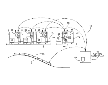
monitoring
system for an air brake arrangement according to the principles of the present
invention.
DETAILED DESCRIPTION OF THE PREFERRED EMBODIMENTS
[0020] It is to be understood that the invention may assume various
alternative
variations and step sequences, except where expressly specified to the
contrary. It is
also to be understood that the specific devices and processes illustrated in
the attached
drawings, and described in the following specification, are simply exemplary
embodiments of the invention.
[0021] According to one preferred and non-limiting embodiment of the present
invention, provided is a brake monitoring system 10 and method for an air
brake
arrangement 12 used in connection with a railcar R, which is part of a consist
making
up a train TR. Certain preferred and non-limiting embodiments of the brake
monitoring system 10 and air brake arrangement 12 are illustrated in schematic
form
in Figs. 2-4.
[0022] It should be noted that while the system 10, method, and arrangement 12
of
the present invention are specifically discussed herein with connection to a
pneumatically-driven brake arrangement (air brakes) for a train TR or railway
vehicle,
they are equally applicable and useful in connection with a variety of braking
arrangements and applications involving vehicles with air-based braking
systems.
Accordingly, the system 10, method, and arrangement 12 may also be used in
6
CA 02869711 2014-10-06
=
WO 2013/165528
PCT/US2013/026831
connection with roadway vehicles, such as cars, trucks, buses, etc. For
example,
many of these vehicles include similar braking arrangements that use pneumatic-
driven braking systems for slowing or stopping the vehicle. Accordingly, while
predominantly discussed in connection with railway vehicles, all similar
applications
are envisioned and may be used in connection with the system 10, method, and
arrangement 12 of the present invention.
[0023] Similarly, the system 10, method, =and arrangement 12 of the present
invention can be used in a variety of types of braking arrangements and
braking
systems used in the railroad industry. In particular, the presently-invented
system 10,
method, and arrangement 12 are equally useful in connection with the brake
arrangement of a railcar, as well as the brake arrangement of the locomotive
or
engine. Still further, while the system 10, method, and arrangement 12 of the
present
invention is preferably used in connection with electronically-controlled
pneumatic
(ECP) air brake systems, it can also be used in connection with dynamic
braking
systems, blended or combination braking systems, emergency braking systems,
and
the like.
[0024] As illustrated in Fig. 2, and in one preferred and non-limiting
embodiment
of the present invention, the system 10 includes one or more sensors 18 that
are
attached to, integrated with, or in fluid communication with at least one
component of
the air brake arrangement 12 and/or braking assembly 16. In this embodiment,
one or
more sensors 18 are operatively positioned and used to measure air pressure in
or
around one or more of the components of the air brake arrangement 12 and/or
the
braking assembly 16. While discussed specifically in connection with a
measurement
of air pressure, the sensor 18 may also be configured or adapted to measure
other air-
based or air-related data, such as flow and the like.
[0025] In this embodiment, the system 10 also includes a local controller 20
configured, adapted, or programmed to determine air brake data 22. In one
preferred
and non-limiting embodiment, the local controller 20 is used to determine air
brake
data 22 based at least partially on the air pressure measured or detected by
the sensor
18. Still further, this air brake data 22 may include a variety of data points
and
information, including, but not limited to, air pressure in at least one
component of the
air brake arrangement 12 and/or braking assembly 16, air pressure over time in
at
least one component of the air brake arrangement 12 and/or braking assembly
16, air
leakage in the air brake arrangement 12 and/or braking assembly 16, air
leakage rate
7
CA 02869711 2014-10-06
=
WO 2013/165528
PCT/US2013/026831
in the air brake arrangement 12 and/or braking assembly 16, air leakage in one
or
more of the components of the air brake arrangement 12 and/or the braking
assembly
16, brake holding prediction data, air level data, and the like. Accordingly,
this air
brake data 22 provides valuable data and information for further processing or
use in
making determinations for effective and controlled train operation.
[0026] For example, some or all of this air brake data 22 can be used in
determining how long air or air pressure can be supplied to one or more of the
components of the air brake arrangement 12 and/or braking assembly 16, which
is
particularly useful in certain emergency events where the main supply of air
has been
terminated or affected. Specifically, the system 10 of the present invention
can
determine how long air from one or more of the other air reservoirs 14 will be
available to hold the braking assembly 16 in the braked position. This, in
turn, will
provide the operator with a timeline or guidance regarding how much time the
crew
has to deploy or start deploying one or more of the manual parking brakes PB
or
mechanical brakes on one or more of the railcars of the train TR.
[0027] As also illustrated in Fig. 2, the system 10 of this embodiment
includes at
least one communication device 24 that is configured, adapted, or programmed
to
transmit at least a portion of the air brake data 22 to a further computer or
control
system, such as a remote controller, a central controller, a vehicle
controller, an on-
board controller of a locomotive, a central dispatch system, or the like. This
communication device 24 may use a variety of architectures and communication
techniques, in both a wireless and hard-wired format. For example, the
communication device 24 may communicate over a hard-wired cable (the trainline
TL) that extends through and between the various railcars of train TR, over
the rails of
the track, and/or over a wireless connection or link either between railcars
or between
the railcar and the locomotive.
[0028] As discussed hereinafter, the local controller 20 may be in a variety
of
forms, including a separate computer or computerized system or component, or a
computerized system or component that is integrated with existing hardware
and/or
software. Further, the local controller 20 includes the appropriate hardware,
software,
firmware, and the like in order to receive, process, and/or transmit data,
such as some
or all of the air brake data 22 (as well as the raw data obtained from the
sensor 18).
Any known computing device and/or interface can be used in connection with,
integrated with, or in replacement of the local controller 20. Further, and as
also
8
CA 02869711 2014-10-06
WO 2013/165528
PCT/US2013/026831
shown in Fig. 2, some or all of the air brake data 22 (and/or the raw data
from the
sensor 18) may be stored in a local database 26, which may be resident on or
present
at the local controller 20. However, and again, this database 26 may be
established as
part of an existing database, e.g., the train or track database in the on-
board controller
of the locomotive, the central databases at central dispatch, and the like.
[0029] As discussed above in connection with Fig. 2, and in one preferred and
non-
limiting embodiment, the component with which the sensor 18 is interacting or
observing is in the form of an air reservoir 14. Of course, in many situations
and
environments, multiple air reservoirs are provided in connection with the air
brake
arrangement 12 and/or braking assembly 16, including, but not limited to, one
or more
auxiliary reservoirs 28, one or more emergency reservoirs 30, and one or more
hatch
reservoirs 32. Further any two or more of these reservoirs 14 may be combined
and/or in fluid communication to create a specified storage volume, such as a
main
reservoir. Any one or more of these reservoirs 28, 30, 32 may be placed in
fluid
communication with or configured to deliver air to any component of the air
brake
arrangement 12, such as the braking assembly 16. Accordingly, when air can no
longer be delivered from the brake pipe BP, air is instead provided through
one or
more of these air reservoirs 28, 30, 32.
[0030] In this manner, and as discussed, the braking assembly 16 is provided
with
the appropriate air and air pressure to maintain the brakes in a closed
position.
However, and as expected in such air brake arrangements 12, leakage occurs in
these
air reservoirs 14. While certain leakage is acceptable, it is desirous to
better
understand the air brake data 22 associated with one or more or these
reservoirs 14 in
order to calculate or determine with more accuracy how long the air brakes
will be
functional (after which the manual parking brakes PB must be used.
Accordingly,
some or all of the air brake data 22 discussed above can be used in making
such a
determination, as well as making further determinations about holding times,
braking
predictions, and other important parameters.
[0031] As seen in Fig. 3, and in one preferred and non-limiting embodiment,
sensors 18 are used in connection with one, a portion of, or all of these
reservoirs 28,
30, 32 for each particular railcar R. Accordingly, the air brake data 22 can
be
collected or obtained from certain specified or all of the railcars R in order
to make
braking determinations and decisions for the entire train TR. This allows for
a more
effective plan to be implemented regarding the use of the manual parking
brakes PB,
9
CA 02869711 2014-10-06
WO 2013/165528
PCT/US2013/026831
as well operation in other emergency situations. Again, some or all of this
air brake
data 22 can be transmitted or delivered over existing cables (trainline TL)
extending
between railcars R, rails of the track, and/or or existing communication
channels in a
wireless format.
100321 In a further preferred and non-limiting embodiment, one or more of the
sensors 18, local controllers 20, and/or communication devices 24 are
partially or
wholly combined or integrated into a unified system. Accordingly, it is
envisioned
that the combined system is capable of measuring or sensing information or
parameters about air in the air brake arrangement 12 and/or braking assembly
16,
processing this data and information to obtain, provide, and/or determine the
air brake
data 22, and transmit or otherwise communicate this information to other
systems 10,
and/or to other remote controllers, such as the on-board controller OBC,
central
dispatch, and the like. The system 10 may include a variety of communicating
components, whether remote or local, where the system 10 determines the
appropriate
air brake data 22 in order to make the above-discussed control systems
regarding
operation of the train TR.
[0033] In another preferred and non-limiting embodiment, the local controller
20 is
integrated with or in the form of an existing controller 34. Accordingly, the
local
controller 20 may be in communication with such an existing controller 34,
incorporated with the existing controller 34, programmed as part of the
existing
controller 34, and/or integrated with the existing controller 34. In this
embodiment,
the presence of the existing controller 34 on or within the air brake
arrangement 12 of
one or more of the railcars R is leveraged for use within the presently-
invented system
10. For example, and when used in connection with an electronically-controlled
pneumatic (ECP) braking arrangement, the air brake arrangement 12 of each
railcar R
normally includes a local controller LC (or control components) that control
and/or
monitor various of the parts and components within the air brake arrangement
12
and/or braking assembly 16. Therefore, this existing controller 34 can be
configured,
adapted, or programmed to further interact with the sensors 18 and determine
the air
brake data 22. Of course, this existing controller 34 may be any remote
controller or
computer on or in communication with the train TR.
[0034] This same concept applies for the communication device 24, which may be
integrated with, in communication with, incorporated with, or programmed as
part of
an existing communication device or communication medium/architecture of the
train
CA 02869711 2014-10-06
WO 2013/165528
PCT/US2013/026831
TR. Still further, and with respect to the air brake data 22, at least a
portion of this air
brake data 22 may be determined on a dynamic basis, a periodic basis,
continually, on
a pre-determined basis, prior to departure, during operation, and/or during an
emergency event. Therefore, this air brake data 22 could be utilized to make
important operational and control decisions before, during, and/or after train
operation
and/or emergency event.
[0035] In a still further preferred and non-limiting embodiment, and as
illustrated in
Fig. 4, the system 10 may also include at least one positioning system 36 that
is
configured to generate position data relating to the train TR, a portion of
the train TR,
one or more of the railcars R, and the like. Accordingly, while a positioning
system
36 is normally used at one or both of the end-of-train or head-of-train, it is
envisioned
that such a positioning position 36 can be used and/or integrated with any of
the
railcars R of the train TR. Further, any one or more of these positioning
systems 36,
such as in the form of a Global Positioning System (GPS) unit, can be
configured,
adapted, or programmed to determine the position of a vehicle, the position of
a train
TR in a track network, the position of at least one railcar R of a train TR in
a track
network, the position of at least one locomotive of a train TR in a track
network, the
grade of a road, and/or the grade of a track T.
[0036] In one preferred and non-limiting embodiment, the grade of the track T
is
used in making a braking decision, along with or as part of the air brake data
22. In
particular, when making a determination of how long one or more of the air
reservoirs
14 can supply or deliver air to the braking assembly 16 (and, thus,
appropriately apply
the brakes), the grade of the track T can be used as an additional factor in
making an
accurate determination. As seen in Fig. 4, certain railcars R of the train TR
are in a
substantially flat grade of the track T, while others are in a substantially
sloped grade
of the track T. Among other considerations, the slope or grade of the track T
can be
used (as part of or calculated using part of the air brake data 22) to make
decisions
about how long the brakes can hold, and when the mechanical or manual parking
brakes PB must be utilized. Further, information from the positioning systems
36
and/or other train data can used to make determinations regarding the use of
the
manual parking brakes PB of specific railcars R. This provides a more managed
approach to be used as to which of the manual parking brakes PB of which
railcar R
should be deployed and when. Furthermore, deciding between the manual parking
11
CA 02869711 2014-10-06
WO 2013/165528
PCT/US2013/026831
brakes PB of different cars can also be part of the decision-making process
based
upon the grade of the track T.
[0037] With continued reference to Fig. 4, and in this preferred and non-
limiting
embodiment, at least a portion of the air brake data 22 is directly or
indirectly
transmitted to or communicated to an on-board controller 38 of a locomotive L
of the
train TR. In this embodiment, the on-board controller 38 (which represents an
existing unit (OBC) used in connection with at least partially automated
trains TR)
determines at least one air brake arrangement condition based at least
partially on the
air brake data 22. Further, at least a portion of the air brake data 22 and/or
at least one
air brake arrangement condition may be directly or indirectly transmitted or
communicated to a central controller 40, such as a central dispatch system.
[0038] Further, in this preferred and non-limiting embodiment, and based at
least
partially on at least a portion of the air brake data 22 of the local
controller 20 and/or
at least one air brake arrangement condition, the central controller 40 is
configured to
determine further air brake data and/or air brake arrangement condition data
or
information. For example, this additional information may include air pressure
in at
least one component of the air brake arrangement 12 and/or braking assembly
16, air
pressure over time in at least one component of the air brake arrangement 12
and/or
braking assembly 16, air leakage in the air brake arrangement 12 and/or
braking
assembly 16, air leakage rate in the air brake arrangement 12 and/or braking
assembly
16, brake holding prediction data, air level data, and the like. This allows
this central
controller 40 to assist in the management and operation of the train TR within
a track
network, as well as the control of multiple trains TR traversing the track
network.
Still further, at least a portion of this additional information, such as in
the form of air
brake data, air brake arrangement condition, control data, operational data,
and the
like may be transmitted or communicated to the local controller 20, a remote
controller, at least one other central controller, a vehicle controller, the
on-board
controller 38 of a locomotive L, a central dispatch system, and the like.
[0039] With continued reference to Fig. 4, the on-board controller 38 of the
locomotive L may be in further communication with a visual display device 42,
which
is used to present data and information to the operator of the train TR. For
example,
in one embodiment, a message or other visual indicia is displayed to the
operator on
the visual display device 42, and the content of this message or visual
indicia may
include some or all of the air brake data 22 and/or an air brake arrangement
condition.
12
CA 02869711 2014-10-06
WO 2013/165528
PCT/US2013/026831
Further any of this data can be stored on a locomotive database 44 integrated
with or
in communication with the on-board controller 38.
[0040] Still further, this message or visual indicia may provide information
and
data to the operator of the train TR regarding the status of the air brake
arrangement
12 of any particular railcar R, the status of the braking assembly 16 of any
particular
railcar R, the condition surrounding any of these air brake arrangements 12
and/or
braking assemblies 16, air brake data 22, and/or any data and information,
such as
timelines, guidance, control decisions, and the like, which could be used in
making
determinations for control of the train TR. For example, the operator may be
provided with timing information or guidelines as to when and which of the
manual
parking brakes PB should be deployed. Accordingly, the operator may use some
or
all of the air brake data 22 or other information provided by the system 10 to
control
or operate the train TR in a safe manner, such as by operating at a specified
speed
limit, slowing the train TR, stopping the train TR, using a suggested air
brake
arrangement 12 and/or braking assembly 16, parking the train TR on a specified
location of the track TR (according to grade), communicating with the crew
about
deploying the manual parking brake PB on one or more of the railcars R, and
the like.
[0041] As further illustrated in Fig. 4, an alarm device 46 is provided in a
locomotive L and integrated with or in communication with the on-board
controller
38. The alarm device 46 is configured to provide some alarm or other
indication to
the operator of the train TR based upon some or all of the air brake data 22
and/or
some air brake arrangement condition. For example, the alarm may be in the
form of
an audio alarm, a visual alarm, a tactile alarm, and the like. Based upon the
nature
and content of the alarm, the operator can manually control the train TR to
achieve a
safe situation, or alternatively, the system 10 may be configured, adapted, or
programmed to automatically implement or enforce such control through the
control
system or on-board controller 38.
[0042] As discussed above, the local controller 20 may be in the form of,
integrated
with, or replaced with an existing controller 34, which, in another preferred
and non-
limiting embodiment, may be in the form of the on-board controller 38. As
discussed,
such on-board controllers 38 are known in the industry, and may be part of a
positive
train control (PTC) system, such as the Electronic Train Management System
(ETMS)
of Wabtec. Such systems often rely upon various databases and on-board
analyses to
provide the operator with accurate train control information, as well as to
confirm safe
13
CA 02869711 2014-10-06
WO 2013/165528
PCT/US2013/026831
train operation. Accordingly, the local controller 20 of the system 10 of the
present
invention may be integrated and/or replaced with such a known on-board
controller
38.
[0043] In a further preferred and non-limiting embodiment and in order to
obtain
appropriate data and information from remote locations, the communication
device 24
(whether local to the railcar R or local on the train TR (e.g., as part of the
on-board
controller 38)) may include a receiver 50. This receiver 50 receives data,
such as the
air brake data 22 and/or some other train or track data, thereby ensuring that
the most
accurate data is available to the overall train control system for determining
the
above-discussed brake control decisions. This receiver 50 may be a
transceiver, a
receiver capable of receiving and/or transmitting wireless signals, and/or a
receiver
capable of receiving hard-wired (e.g., trainline TL and/or rail-based
signals). This
receiver 50 may obtain data from a variety of sources, e.g., a central
dispatch system
(or central controller 40), a wayside unit, a wayside-based detection system,
an off-
board database 48, and the like.
[0044] As also discussed above, some or all of the air brake data 22 and/or
some air
brake arrangement condition (or other similar data), braking data, train data,
track
data, position data, and the like, may be provided to a remote central
controller 40,
and stored in a database 48. As discussed, this central controller 40 is in
communication with the on-board controller 38 and/or the local controllers 20
on one
or more of the railcars R of the train TR via the receiver 50 and/or the
communication
devices 24 discussed above. Therefore, any important braking information,
deployment of the manual parking brake PB, or other train control information
and
data can be communicated to the train TR for use in making train control
decisions.
Any number of communication paths and data transfer processes are envisioned
within the context and environment of the present invention, such that the
appropriate
train control decisions can be made based upon the measurements of the sensors
18
and/or the air brake data 22.
[0045] As discussed above, the presently-invented brake monitoring system 10
can
be used in connection with a variety of air brake arrangements 12 and/or
braking
assemblies 16. For example, and in one preferred and non-limiting embodiment,
the
braking assembly 16 is in the form of a known brake cylinder/piston
arrangement,
which is effective in urging the brake shoe mechanism BS against the wheel W
of the
railcar R of the train TR. However, in another embodiment, the braking
assembly 16
14
CA 02869711 2014-10-06
WO 2013/165528
PCT/US2013/026831
is in the form of a bladder that can be expanded and deflated through
injection of air,
which, as discussed above, urges the brake shoe mechanism BS against the wheel
W.
One example of this bladder-type braking assembly is the UBX-type braking
assembly of Wabtec. By using such a bladder-type braking assembly, the most
common source of air leakage, namely leakage in the brake cylinder BC during
operation, is eliminated. Further, this bladder-type braking assembly provides
the
ability to fully seal the air, in a manner similar to automobile tires and the
like. In
another preferred and non-limiting embodiment, the air brake arrangement 12
includes an ECP control valve manifold, which is designed to pneumatically
connect
the reservoir 14 to the braking assembly 16 following the loss of pressure in
the brake
pipe BP. This pneumatic connection is retained even after electrical power to
the
ECP manifold is removed. Further, it is envisioned that this ECP control valve
manifold functions in connection with or is integrated with the local
controller 20.
[0046] As discussed above, the system 10 of the present invention can
implement
or use a variety of measurements (as provided by the sensor 18). For example,
in one
preferred and non-limiting embodiment, two levels of air leak measurement are
provided. One level of air leak measurement is provided in the form of
departure
testing, which is a "low leak" measurement for determining air brake data 22,
such as
in the form of predicting the brake holding capacity or capability for each
railcar R in
the train TR. A second level of leak measurement is an ongoing "mid leak"
alarm
measurement, which provides air brake data 22 in the form of a warning if a
railcar R
is showing a change in holding capacity during normal brake applications.
Again,
such a measurement may produce information and data sufficient to trigger the
alarm
device 46 in the locomotive L. Further, it is envisioned that the system 10
can
provide any level of air leak measurement using air pressure, flow, or the
like, and
represents a pneumatic-control approach for determining air leakage and other
changes during normal brake applications.
[0047] As discussed above, and in another preferred and non-limiting
embodiment,
the brake monitoring system 10 provides a variety of ways of communicating air
leak
information (and/or air brake data 22). One means of communication is over the
ECP
trainline TL (such as by cable) to the controlling locomotive L to provide
information
to the crew if railcars R have leaks above a defined level. This information
can be
provided in the form of alarm activation or other indication to the operator.
This will
be useful in identifying railcars R where the manual parking brake (or hand
brake) PB
CA 02869711 2014-10-06
WO 2013/165528
PCT/US2013/026831
will need to be set within a defined time. Another manner of communication is
through the use of a data radio (as the communication device 24) positioned on
each
railcar R, which sends air brake data 22, such as alarm messages or similar
data, to a
maintenance back office application, such as in the form of a central
controller 40 (or
central dispatch system). Of course, this wireless communication may occur
through
a cellular format, a satellite format, and/or any other type of effective data
radio
transmission, with the ability to communicate to the central office
application. It is
further envisioned that the air brake data 22 can be sent to the locomotive L,
such as
over the trainline TL, and thereafter, relayed to the central controller 40,
as discussed
above. Similarly, the information and data from the positioning system 36
provided
on one or more of the railcars R and/or locomotive L can be sent directly or
indirectly
to the central controller 40, such as directly to the central controller 40
(or some other
remote controller), or as relayed by the on-board controller 38 in the
locomotive L.
[00481 In a still further preferred and non-limiting embodiment, the
maintenance
back office application (or central controller 40) is provided with the
appropriate
communication systems and devices to provide data back to the train TR in
order to
provide further air brake data 22, such as air holding prediction times for
certain
railcars R of interest. This communication may also be implemented using a
variety
of means and devices, such as direct wireless connections between the central
controller 40 and one or more of the railcars R of the train TR, or back to
the
locomotive L using the standard wireless communication techniques. Still
further, the
central controller 40 may be configured, adapted, or programmed to provide
periodically updated calculations of predicted railcar R holding times, at
least partially
based upon the air brake data 22, the data from the sensors 18, and/or
information or
data from the positioning systems 36. In addition to analyzing the airbrake
data 22 for
individual railcars R, this analysis and determination process may be on a car
consist
and/or train TR basis. For example, one railcar R out of a 10-railcar consist
may
completely lose its air-holding capacity without the need for maintenance
attention.
The logic at the central controller 40 (and/or the on-board controller 38) may
also be
enhanced by using the positioning system 36 information and data from the
railcars R,
as referenced to a track database 38, to determine the grade and minimum brake
cylinder pressure per railcar R consist as needed to safely hold the coupled
group of
railcars R.
16
CA 02869711 2014-10-06
WO 2013/165528
PCT/US2013/026831
[00491 As discussed above, and in another preferred and non-limiting
embodiment,
some railcars R may be equipped with pneumatically-operated door or hatch
systems,
which include a hatch reservoir 32 to support and operate these systems. Where
equipped, a small pneumatic line, with a choke and a check valve, can be
connected
between the hatch reservoir 32 and the auxiliary reservoir 28 and/or emergency
reservoir 30 (or any of the reservoirs 14 in the air brake arrangement 23).
This
provides the functional ability to increase the pneumatic capacity to hold air
and
compensate for small leaks for a long period of time. In this embodiment, this
line
may have a choke sized to be only slightly larger than the highest acceptable
brake
cylinder leak rate, such that there would be no significant impact to the
normal
emergency brake equalization pressure within the time needed for the railcar R
to
come to a stop. In a leak-free system, the brake cylinder BC pressure would
slowly
increase to equalize both the brake (auxiliary and/or emergency) reservoir and
the
hatch reservoir 32, as a combined system. Further, if there were a slow leak,
the
holding time could be extended by the combined reservoir system. A choke may
also
be used in the line connecting the reservoirs 14 to protect against a leak in
the hatch
reservoir 32, which would serve to isolate the impact to the other reservoirs
14. As
discussed above, a sensor 18 may also be used in connection with this hatch
reservoir
32 in order to further enhance the ability to detect holding capability, leak
rates, and
any other air brake data 22.
100501 As discussed above, eliminating or minimizing air leaks is important in
the
operation and control of an air brake arrangement 12 for a train TR. One way
of
minimizing such air leaks may be through the use of the above-discussed
bladder-type
braking assembly 16. Other leaks may be minimized based upon the upkeep and
maintenance of good pipe fittings, insulations, leak-free reservoirs, and
enhanced air
holding capabilities with the ECP control valve manifold. The brake monitoring
system 10 of the present invention allows for the detection of air pressure,
air flow,
and the like, in order to determine air brake data 22, such as leak rate. Such
a
determination provides a reliable prediction of the railcar R holding
capability
through the use of the local controller 20, the on-board controller 38, and/or
the
central controller 40. In addition, this air brake data 22, such as leak data,
may be in
the form of a slow-leak measurement (as part of the ECP train TR
initialization
process), and'or supplemented by routine leak detection during brake
applications or
at any other stage of operation of the train TR.
17
CA 02869711 2014-10-06
WO 2013/165528
PCT/US2013/026831
[0051] As discussed, the brake monitoring system 10 may facilitate or
implement
the communication of air hold pressure and leak rate information (or any other
air
brake data 22) to the central controller 40 (such as a central dispatch
system) to
provide ongoing updates of holding capacity on an individual railcar R basis,
a consist
basis, a train TR basis, and the like. Further, the system 10 of the present
invention
can use a variety of communication techniques and platforms, such as the
existing
ECP trainline TL, or independent hard-wired or wireless media, such as radio
data
communications and the like. Further, and as discussed, the central controller
40,
such as the maintenance back office server may be used to communicate further
air
brake data 22, such as alarms and the like, to maintenance crews, as well as
confirm
the holding time remaining for the railcar R, consist, and/or train TR. The
communication of this information may take a variety of forms, including
delivery by
voice from a person with access to a workstation connected to the central
controller
40, or directly by a variety of data radio alternatives, cellular
communication, text
messaging communication, smart phone communication, and the like.
[0052] In this manner, the brake monitoring system 10 and air brake
arrangement
12 of the present invention allows crews extended time before manual parking
brakes
PB need to be set, which, in many cases, may eliminate the need to set them at
all
before the railcars R are returned to normal operation in the train TR.
Similarly, the
brake monitoring system 10 may be used in connection with a variety of
different
types of air brake arrangements 12 and/or braking assemblies 16, such as the
above-
discussed bladder-type brake assembly 16, which will provide further air
holding
times based upon their construction. For example, a freight car equipped with
this
brake monitoring system 10 (whether or not in connection with ECP brake
control,
both overlay and standalone types) and bladder-type braking assembly 16 allows
the
use of certain existing hardware and programmable components to provide the
functionality of the brake monitoring system 10. For example, and as
discussed, the
local controller 20 may be in the form of an existing controller 34, which may
be
configured, adapted, or programmed to provide the air hold parking brake
function
and/or include a radio and/or data communications module. In particular, when
this
local controller 20 is in the form of an existing controller 34, it would
already have
the appropriate configuration or programming to access brake cylinder BC,
braking
assembly 16, and/or reservoir 14 pressures. Still further, the use of an
existing
communication device 24 and/or communications module (on the local controller
20
18
, CA 02869711 2014-10-06
WO 2013/165528
PCT/US2013/026831
and/or existing controller 34) can be configured, adapted, or programmed to
report
railcar R location and other air brake arrangement 12 and railcar R
information, in
addition to the air hold parking brake status. Such additional information or
data may
be obtained from other sensors equipped on the railcar R with interfaces to
the local
controller 20.
[0053] In a still further preferred and non-limiting embodiment, at
least one other ,
or separate air reservoir 14 may be in fluid communication with at least one
other air
reservoir 14 of or within the air brake arrangement 12, In this embodiment,
fluid
communication between these separate air reservoirs 14 can be controlled. In
addition, the fluid communication between these separate reservoirs may be
controlled based at least partially upon the air brake data 22. This provides
an
additional level of control for ensuring that the proper and appropriate air
reservoirs
14 are charged with air for use in an emergency or other application. For
example, if
the air leakage, air pressure, and/or air leakage rate is determined to be
outside of
acceptable limits with a specific air reservoir 14, it is envisioned that at
least one other
air reservoir 14 can be used then to transfer or otherwise provide air to this
compromised air reservoir 14, Of course, this only represents one useful
application
of the air brake data 22 in making braking and other operational decisions.
[0054] One primary benefit of the brake monitoring system 10 and air brake
arrangement 12 of the present invention is lowering of the recurring hardware
costs
for equipping freight cars to reduce the need for a manual application of the
manual
parking brake PB. Another advantage of the brake monitoring system 10 is that
it is
easily integrated with existing equipment on certain ECP-equipped railcars R,
which
include existing controllers 34 and existing communication devices 24. The
integrated brake monitoring system 10 of the present invention provides a much
preferable alternative to mechanical locking systems and arrangements. Still
further,
the brake monitoring system 10 and the air brake arrangement 12 of the present
invention facilitates the reduction of the risk of crew injuries related to
the manual
operation of the manual parking brake PB. A further advantage to the brake
monitoring system 10 and air brake arrangement 12 of the present invention is
through the use of the existing communication platforms and systems for daily
communication between the railcars R, the locomotive L, and/or the central
controller
40, which then may support predictive maintenance of freight cars and other
trains
TR.
19
CA 02869711 2014-10-06
WO 2013/165528
PCT/US2013/026831
[0055] In this manner, and in one preferred and non-limiting embodiment, the
brake monitoring system 10 and air brake arrangement 12 can be used to predict
leakage rates and communication this information to the locomotive L as a
first level
to predict railcar R holding time following an emergency brake application.
Further,
and in another preferred and non-limiting embodiment, the brake monitoring
system
and air brake arrangement 12 provide the ability to communicate revisions to
the
predicted brake holding times after a "break-in-two" event to provide the crew
with
an estimate of the railcar R brake holding time. Still further, and as
discussed in
connection with another preferred and non-limiting embodiment, the brake
monitoring system 10 and air brake arrangement 12 can extend the braking
assembly
16 holding time through the use of the hatch reservoir 32 to supplement the
main air
reservoir(s) to counter leakage conditions, and to extend the railcar R brake
holding
time. In addition, and as discussed in connection with a further preferred and
non-
limiting embodiment, the brake monitoring system 10 and air brake arrangement
12
can be used in connection with a bladder-type braking assembly 16 (as opposed
to a
known air cylinder-type braking assembly 16) to further minimize air leakage
in the
air brake arrangement 12, and extend the railcar R brake holding time.
[0056] Although the invention has been described in detail for the purpose of
illustration based on what is currently considered to be the most practical
and
preferred embodiments, it is to be understood that such detail is solely for
that
purpose and that the invention is not limited to the disclosed embodiments,
but, on the
contrary, is intended to cover modifications and equivalent arrangements that
are
within the spirit and scope of the appended claims. For example, it is to be
understood that the present invention contemplates that, to the extent
possible, one or
more features of any embodiment can be combined with one or more features of
any
other embodiment.