Note: Descriptions are shown in the official language in which they were submitted.
CA 02869789 2019-09-09
WO 2013/139461
PCT/EP2013/000816
1
10
System for the transmission of electrical current
The invention relates to a system for the transmission of electrical current
comprising at least two electrically conducting rigid conductors which are
connected with one another.
It is known for electrical current and in particular high current to be
transmitted
via conductors which are designed as large-volume, solid metal components,
i.e.
which are substantially rigid. The use of rigid conductors leads to the
problem
that electrical functional elements which are to be connected via these
conductors need to be positioned relatively exactly in relation to one
another,
since a compensation of positioning tolerances is not readily possible due to
the
rigidity of the conductors. This problem could be solved in that the at least
two
conductors of the system are connected together with a defined play. However,
in that case the contact surface area between the two conductors varies
depending on their relative location, which could be associated with an
unsatisfactory transmission behaviour for the current.
For example it is known, in the drive train of an electric motor vehicle, for
a power
distributor to be connected with the power electronics via a system of rigid
conductors.
Starting out from this prior art, the invention was based on the problem of
WO 2013/139461
PCT/EP2013/000816
2
providing a system of this generic category comprising at least two rigid
conductors, connected together in an electrically conducting manner, which,
despite the possibility of a tolerance compensation with regard to the
positioning
of electrical functional elements which are to be connected by means of this
system, guarantees reliable transmission behaviour.
According to the invention, a system of this generic category for the
transmission
of electrical current (both for the supply of energy and for the transmission
of
signals (including radio frequency signals)) and in particular of high current
48
V voltage of the current source) with at least two rigid conductors connected
together in an electrically conducting manner is further developed in that the
two
conductors are (indirectly) connected (in an electrically conducting manner)
via at
least one electrically conducting, deformable connecting element.
The deformable connecting element ensures a relative movability of the rigid
conductors, through which tolerances in terms of the positioning of electrical
functional elements which are to be connected via the system according to the
invention can be compensated,
The connecting element can particularly preferably comprise a (preferably
cylindrical) helical spring which is shaped like a closed ring in the
direction of the
longitudinal axis thereof and which grips a section of a first conductor under
pre-
tension. This gripping of the first conductor under pre-tansion ensures a
permanent contacting between the conductor and the helical spring.
A contact between the ring-formed helical spring and at least the second,
preferably both conductors, preferably takes place in a radial plane formed by
the
ring-formed helical spring; the helical spring thus contacts the conductor(s)
in a
CA 2869789 2018-01-18
CA 02869789 2019-09-09
WO 2013/139461
PCT/EP2013/000816
3
ring-formed manner and consequently over a relatively wide area. This allows a
good transmission behaviour for the current flowing via the system to be
achieved.
Particularly preferably, (at least) two helical springs can be provided which
each
grip a section of the first conductor under pre-tension and which each contact
the
second conductor in a radial plane formed by the relevant helical spring. This
allows the effective surface area for the transmission of the current to be
relatively large.
In order to ensure that the helical springs are in permanent contact with the
second conductor and thus ensure a good electrical transmission behaviour, it
can also be the case that these are pressed against the second conductor by
means of (in each case) a contact element.
Particularly preferably, the contact element(s) themselves are thereby
electrically
conducting in design and also connected in an electrically conducting manner
with the first conductor. As a result, the first conductor contacts the ring-
formed
helical spring(s) not only on their inner side (with which the latter grips
the first
conductor), but also, in addition, via the contact element(s). As a result,
the
effective surface area for transmission of the current can, again, be
increased.
Preferably, the second conductor, which can for example be designed in the
form
of a flat component, has an opening through which the first conductor, which
can
for example be pin-formed (at least in one section) extends. Particularly
preferably, at least one dimension of the opening of the second conductor is
greater than the corresponding external dimension of the first conductor in
the
section thereof accommodated in the opening. As a result, a relative
movability
of the conductors in a plurality of directions is guaranteed.
Preferably, it can also be the case that the opening as well as the section of
the
first conductor accommodated therein are circular in cross section, wherein
the
difference in diameter amounts to between 0.1 mm and 0.2 mm.
CA 02869789 2019-09-09
WO 2013/139461
PCT/EP2013/000816
4
The invention is described in more detail in the following with reference to
an
embodiment illustrated in the drawings, in which:
Fig.1: shows an isometric exploded representation of a system according to the
invention; and
Fig. 2: shows a cross section through the system according to the invention as
shown in Fig. 1.
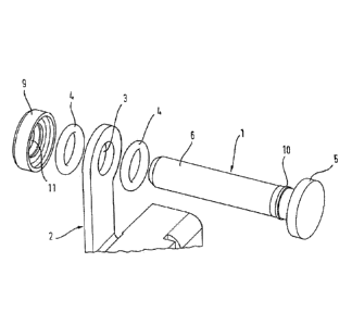
Figs. 1 and 2 show different views of a system according to the invention for
the
transmission of high current, such as can be used, for example, in the drive
train
of an electric motor vehicle.
The system comprises two conductors 1, 2, which are designed as relatively
large-volume, solid metal components and are therefore substantially rigid. A
deformation of the conductors 1, 2 during installation, for example in order
to
compensate positioning tolerances of electrical functional elements which are
to
be connected by means of the system is not therefore possible. The conductors
1, 2 are large-volume and solid in design in order to minimise their
electrical
resistance and consequently power loss during the transmission of high
currents.
The first of two conductors 1 is pin-formed and the second conductor 2 is
designed as a contact rail, i.e. as a flat component. The second conductor 2
has
an opening 3 through which the first conductor 1 projects when the system is
in
its installed state. As can be seen from Fig. 2, the diameter of the opening 3
is
greater than the external diameter of the first conductor 1 in the section in
which
the latter is accommodated in the opening. Through this difference in
diameter,
which can for example amount to between 0.1 mm and 0.2 mm, a defined
movability between the two conductors 1, 2 can be achieved, not only along the
longitudinal axis of the first conductor 1 but also in a radial direction
thereto. This
also permits a tilting (where the longitudinal axis of the first conductor is
no
longer aligned perpendicular to the large lateral surfaces of the second
CA 02869789 2019-09-09
WO 2013/139461
PCT/EP2013/000816
conductor) of the first conductor 1 relative to the second conductor 2.
The relative movability of the two conductors 1, 2 in relation to one another
guarantees a compensation of positioning tolerances in the electrical
functional
5 elements which are to be connected by means of the system according to
the
invention.
In order to guarantee a reliable transmission of the high current via the
system,
irrespective of the relative position of the two conductors 1, 2, the
transmission
path for the high current from the first conductor 1 to the second conductor 2
is
formed via two deformable connecting elements. As a result it is possible to
prevent the effective surface area of the transmission path for the high
current
from changing depending on the relative position of the two conductors 1, 2 in
relation to one another. Instead, due to the deformability of the connecting
elements, the contact surface areas between the connecting elements on the
one hand and the two conductors on the other substantially remain the same
size, irrespective of the relative position of the conductors 1, 2 in relation
to one
another.
The connecting elements are designed in the form of helical springs 4 which
form
a closed ring in relation to the longitudinal axis defined by the coils (in
relation to
the coils). The internal diameters of the two ring-formed helical springs 4
(in their
unloaded state) are thereby slightly smaller than the external diameter of the
first
conductor 1 in those sections in which it grips the first conductor 1
following
installation of the system. This leads to the helical springs 4 expanding
radially
when these grip the corresponding sections of the first conductor 1, which as
a
result of the elastic reaction forces ensures that the helical springs 4
contact the
first conductor 1 securely around its entire circumference.
The second conductor 2 is contacted on its two large lateral surfaces by in
each
case one of the helical springs 4 in a radial plane formed by the relevant
helical
spring 4, i.e. in a ring-formed manner.
CA 02869789 2019-09-09
WO 2013/139461
PCT/EP2013/000816
6
In order to ensure a permanent contact between the two helical springs 4 and
the
second conductor 2, these are pressed against the second conductor 2 in each
case via an electrically conducting contact element. One contact element is
thereby formed as the head part 5 of the first conductor 1, which has a larger
diameter in comparison with a pin-formed base body 6 of the first conductor 1.
The head part 5 forms a ring-formed recess 7 in which the associate helical
spring 4 is accommodated. The ring-formed recess 7 is formed by a ring-formed
collar 8, the longitudinal extension of which is chosen such that the
(unloaded)
helical spring 4 still projects from this slightly. As a result it is ensured
that when
the head part 5 only presses gently against the helical spring 4 a defined
distance still remains between the collar 8 and the second conductor 2, which
ensures the desired movability of the first conductor 1 and the second
conductor
2 in relation to one another.
The second contact element is in the form of a contact sleeve 9 which also
possesses a collar 8 which forms a ring-formed recess 7 into which the
associated helical spring 4 is almost completely received. This collar 8 is
also so
dimensioned that when the contact sleeve 9 only exerts a gentle pressure on
the
helical spring 4 a distance remains between the collar 8 and the second
conductor 2.
The minimal distance between the two contact elements is defined
constructively, for which purpose a ring-formed projection 10 is provided
against
which the contact sleeve 9 comes to rest. As a result it is ensured that
during
installation of the system the contact sleeve 9 cannot pushed too far in the
direction of the head part 5, which could otherwise lead to the distances
between
the contact elements and the second conductor 2 being too short.
The connection of the contact sleeve 9 with the first conductor 1 is force-
locking,
in that the internal diameter of the central opening 11 of the contact sleeve
9 is
slightly less than the external diameter of a fixing section 12 of the first
conductor
1. However, the difference in diameter is preferably so small that the contact
sleeve 9 can be pushed onto the fixing section 12 manually or with the
CA 02869789 2019-09-09
WO 2013/139461
PCT/EP2013/000816
7
assistance of a hand tool. However, the possibility also exists of forming a
press
fit by heating the first conductor 1 and the contact sleeve 9 to different
temperatures.
The fixing section 12 of the first conductor 1 has a slightly larger diameter
than
the section of the base body 6 preceding it in the plugging direction. As a
result,
the contact sleeve 9 can, without significant application of force, be plugged
onto
the base body 6 of the first conductor 1 and pushed as far as the fixing
section
12.
The system according to the invention is assembled in that one of the helical
springs 4 is first pushed onto the base body 6 of the first conductor 1 until
this is
received in the ring-formed recess 7 of the head part 5. The base body 6 of
the
first conductor 1 is then inserted through the opening 3 of the second
conductor
2. The other helical spring 4 is then pushed onto the base body 6 of the first
conductor 1 and finally the contact sleeve 9 is pushed onto the fixing section
12
of the first conductor 1.
The design of the system according to the invention enables the two conductors
1, 2 to be relatively movable (within limits) in relation to one another, both
along
the longitudinal axis of the first conductor 1 and also in a radial direction
to this. A
tilting of the first conductor 1 and second conductor 2 in relation to one
another is
also possible. The effective surface area for the transmission of the high
current
thereby substantially always remains the same, since the relative movement of
the two conductors 1, 2 is absorbed by the elastically deformable helical
springs
4 without the size of the contact surface areas between the two conductors 1,
2
and the two helical springs 4 changing significantly.