Note: Descriptions are shown in the official language in which they were submitted.
CA 02869996 2014-10-08
-1-
DESCRIPTION
A VACUUM INSULATING GLAZING, A SEALING, AND A
METHOD OF PRODUCING VACUUM INSULATING GLAZING
TECHNICAL FIELD
The present invention relates to a vacuum
insulating glazing, a sealing for a vacuum insulating
glazing, and a method of producing a vacuum insulating
glazing.
BACKGROUND ART
"Vacuum insulating glazing" is formed by
stacking a pair of glass substrates leaving a gap
between them and maintaining the gap at a low pressure
or in a vacuum state. A vacuum insulating glazing has
excellent heat insulating properties, and is therefore
widely used for windowpanes of, for example, buildings
and residential houses.
The heat insulating properties of entire
vacuum insulating glazing is greatly affected by a
sealing performance of a sealing provided peripherally
between glass substrates to maintain a gap in a vacuum
state. When the sealing performance of the sealing is
low, components of an atmospheric gasses, such as air
and/or moisture easily enter into the gap, and the
degree of vacuum of the gap is deteriorated. For this
reason, research on a sealing having higher sealing
performance is being conducted.
Particularly, "hybrid sealings", which are
composed of a metal component and a non-metal component,
are under development. For example, Patent Document 1
discloses using a "hybrid sealing" composed of a metal
component and a low-melting ceramic frit for vacuum
CA 02869996 2014-10-08
-2-
insulating glazing.
[RELATED-ART DOCUMENT]
[Patent Document]
[Patent Document 1] European Patent No. 2099997
DISCLOSURE OF INVENTION
PROBLEMS TO BE SOLVED BY THE INVENTION
As described above, Patent Document 1
discloses a "hybrid sealing" composed of a metal
component and a low-melting ceramic frit.
However, to actually use the hybrid sealing
disclosed by Patent Document 1 for vacuum insulating
glazing, the bonding force between the metal component
and the low-melting ceramic frit needs to be strong.
When the bonding force between the metal component and
the low-melting ceramic frit is weak, the "hybrid
sealing" cannot provide an excellent sealing performance.
In Patent Document 1, no consideration is
given to the bonding force between the metal component
and the low-melting ceramic frit of the "hybrid sealing".
Therefore, depending on a combination of materials of
the metal component and the low-melting ceramic frit,
the bonding force may become insufficient. Also, if such
an insufficient combination is selected, it is not
possible to form a "hybrid sealing" with an excellent
sealing performance.
The present invention is made by taking into
account the above mentioned background. One object of
the present invention is to provide vacuum insulating
glazing including a "hybrid sealing" including a metal
component and a glass layer that bond well to each other.
Another object of the present invention is to provide
CA 02869996 2014-10-08
-3-
such a "hybrid sealing". Still another object of the
present invention is to provide a method of producing a
vacuum insulating glazing including such a "hybrid
sealing".
MEANS FOR SOLVING THE PROBLEMS
The present invention provides a vacuum
insulating glazing including first and second glass
substrates that are stacked leaving a gap through a
"hybrid sealing" at a pressure less than an atmospheric
pressure. The "hybrid sealing" includes a metal
component and a glass layer that bonds the metal
component and the glass substrates. A material for the
metal component is selected from materials whose tensile
strength X (N/mm2) and breaking elongation Y (%) satisfy
a relationship Y 0.10X
by a room temperature tensile
test (tensile speed: 1 ram/min) that is performed after
the materials are kept at 490 t for 40 minutes in an
atmosphere.
In the vacuum insulating glazing of the
present invention, the metal component may have a
thickness between 0.03 mm and 0.5 mm.
In the vacuum insulating glazing of the
present invention, the material as the metal component
may be selected from materials whose tensile strength x
(N/mm2) and breaking elongation Y (%) do not satisfy the
relationship Y 0.10X
by a room temperature tensile
test (tensile speed: 1 ram/min) that is performed before
the materials are kept at 490 C for 40 minutes in the
atmosphere.
In the vacuum insulating glazing of the
present invention, the metal component may include at
least one component selected from the group consisting
CA 02869996 2014-10-08
-4-
of pure aluminum, an aluminum alloy, pure titanium, and
a titanium alloy.
In the vacuum insulating glazing of the
present invention, the glass layer includes a glass
component whose thermal expansion coefficient maybe
greater than or equal to 70x10-7/K and less than or equal
to 120x10-7/K.
In the present application, the thermal
expansion coefficients indicate values at a temperature
of between 50 t and 250 t.
In the vacuum insulating glazing of the
present invention, the glass layer may include a glass
component that is ZnO-Bi203-B203 glass.
In this case, the glass component included in
the glass layer may have the following composition in
terms of mass percentage of oxide:
3i203 70%-90%, ZnO 5%-15%, B203 2%-8%, A1203
0.1%-5%, Si02 0.1%-2%, Ce02 0.1%-5%, Fe203 0.01%-0.2%,
and CuO 0.01%-5%.
In the vacuum insulating glazing of the
present invention, the glass layer includes a glass
component that may be ZnO-SnO-P205 glass.
In this case, the glass component included in
the glass layer may have the following composition in
terms of mass percentage of oxide:
P205 27%-35%, SnO 25%-35%, ZnO 25%-45%, 3203
0%-5%, Ga203 0%-3%, CaO 0%-10%, Sr0 0%-10%, A1203 0%-3%,
In203 0%-3%, La203 0%-3%, and A1203+In203+La203 0%-7%.
In the vacuum insulating glazing of the
present invention, the metal component may include a
first portion and a second portion. The first portion of
the metal component may be bonded to a first glass layer
formed on the first glass substrate and the second
CA 02869996 2014-10-08
A
-5-
portion of the metal component may be bonded to a second
glass layer formed on the second glass substrate to form
the peripheral seal.
The present invention also provides a sealing
of a vacuum insulating glazing including first and
second glass substrates stacked leaving with a gap that
is set at a pressure less than an atmospheric pressure
through the peripheral sealing. The sealing includes a
metal component and a glass layer that bonds the metal
component and the glass substrates. A material as the
metal component is selected from materials whose tensile
strength X (N/mm2) and breaking elongation Y (%) satisfy
a relationship Y 0.10X by a room temperature tensile
test (tensile speed: 1 mm/min) that is performed after
the materials are kept at 490 t for 40 minutes in an
atmosphere.
The present invention also provides a method
of producing a vacuum insulating glazing including first
and second glass substrates stacked leaving with a gap
that is set at a pressure less than an atmospheric
pressure. The method includes forming a first glass
layer on the first glass substrate and forming a second
glass layer on the second glass substrate; forming an
assembly including the gap formed therein by combining a
metal component with the first and second substrates
such that the metal component contacts the first and
second glass layers; heating at least the first and
second glass layers of the assembly to bond the first
and second glass layers and the metal component; and
depressurizing the gap. A material as the metal
component is selected from materials whose tensile
strength X (N/mm2) and breaking elongation Y (%) satisfy
a relationship Y 0.10X by a room temperature tensile
CA 02869996 2014-10-08
-6-
test (tensile speed: 1 mm/min) that is performed after
the materials are kept at 490 t for 40 minutes in an
atmosphere.
In the heating process, at least the first and
second glass layers of the assembly may be kept at a
temperature between 470 t and 530 t for a period of
time between one minute and one hour, and then cooled to
a room temperature.
ADVANTAGEOUS EFFECT OF THE INVENTION
The present invention makes it possible to
provide vacuum insulating glazing including a "hybrid
sealing" including a metal component and a glass layer
that bond well to each other. The present invention also
makes it possible to provide such a "hybrid sealing".
The present invention also makes it possible to provide
a method of producing a vacuum insulating glazing
including such a "hybrid sealing".
BRIEF DESCRIPTION OF THE DRAWINGS
FIG. 1 is a schematic diagram illustrating an
exemplary configuration of vacuum insulating glazing
according to the present invention;
FIG. 2 is a drawing illustrating a problem
that is likely to occur when forming a hybrid sealing on
a glass substrate by bonding a metal component and a
glass layer by a heat treatment;
FIG. 3 is a flowchart illustrating an
exemplary method of producing vacuum insulating glazing
according to the present invention;
FIG. 4 is a graph plotting relationships
between tensile strength and breaking elongation of
metal materials of samples 1-17 measured by a tensile
CA 02869996 2014-10-08
-7-
test in a first example;
FIG. 5 is a schematic plan view of an
evaluation specimen used in a second example;
FIG. 6 is a schematic diagram illustrating a
configuration of a test apparatus used for a bonding
force evaluation test;
FIG. 7 is a graph illustrating a relationship
between a displacement (mm) and a load (N) in a bonding
force evaluation test using an evaluation specimen No.
1; and
FIG. 8 is a graph illustrating a relationship
between displacement (mm) and a load (N) in a bonding
force evaluation test using an evaluation specimen No. 4.
DESCRIPTION OF EMBODIMENTS
Embodiments of the present invention are
described below with reference to the accompanying
drawings.
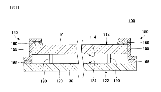
FIG. 1 is a schematic diagram illustrating an
exemplary configuration of vacuum insulating glazing
according to the present invention.
As illustrated by FIG. 1, vacuum insulating
glazing 100 of the present invention includes a first
glass substrate 110, a second glass substrate 120, a gap
130 formed between the first glass substrate 110 and the
second glass substrate 120, and a sealing 150 for
sealing the gap 130.
The first glass substrate 110 includes a first
surface 112 and a second surface 114. The first glass
substrate 110 is disposed such that the first surface
112 forms an outer surface of the vacuum insulating
glazing 100. Similarly, the second glass substrate 120
includes a first surface 122 and a second surface 124.
CA 02869996 2014-10-08
-8-
The second glass substrate 120 is disposed such that the
first surface 122 forms an outer surface of the vacuum
insulating glazing 100. Accordingly, the gap 130 is
formed between the second surface 114 of the first glass
substrate 110 and the second surface 124 of the second
glass substrate 120.
Normally, the gap 130 is maintained in a
vacuum state. The vacuum pressure in the hap 130 may be
any value that is lower than the atmospheric pressure.
Generally, the pressure in the gap 130 is between about
0.001 Pa and about 0.2 Pa.
The gap 130 may be filled with an inert gas
such as argon at a pressure lower than the atmospheric
pressure. Thus, in the present application, a gap in
"vacuum insulating glazing" may not necessarily be in a
vacuum state, and the term "vacuum insulating glazing"
indicates any insulating glazing including a gap whose
pressure is less than the atmospheric pressure.
When necessary, the vacuum insulating glazing
100 may include one or more spacers 190 in the gap 130.
The spacers 190 maintain the gap 130 with the desired
separation. However, the spacers 190 may be omitted when
the gap 130 can be maintained with the desired
separation without the spacers 190. For example, the
spacers 190 may be omitted when the degree of vacuum in
the gap 130 is low, or when the gap 130 is filled with
an inert gas at a certain pressure.
The sealing 150 is a part for sealing the gap
130. In the example of FIG. 1, the sealing 150 is
provided along the entire circumference of the gap 130
peripherally.
The sealing 150 is a "hybrid sealing" that
includes a metal component 155 and first and second
CA 02869996 2014-10-08
-9-
glass layers 160 and 165. As described later in more
detail, the glass layers 160 and 165 which include a
glass component are formed by heat-treating glass frit
paste and bulk glass (e.g., glass fibers or glass
ribbons).
As described above, Patent Document 1
discloses a "hybrid sealing" composed of a metal
component and a low-melting ceramic frit as a sealing
for vacuum insulating glazing. However, in Patent
Document 1, no consideration is given to the bonding
force between the metal component and the low-melting
ceramic frit.
However, in considering whether to actually
use the "hybrid sealing" for vacuum insulating glazing,
the bonding force between the metal component and the
low-melting ceramic frit is a very important factor.
Particularly, depending on a combination of materials of
the metal component and the low-melting ceramic frit,
the bonding force between them may become insufficient
and the "hybrid sealing" may become unusable as a
sealing for vacuum insulating glazing.
For example, Patent Document 1 discloses a
chromium metal and a stainless steel as metal materials
for the "hybrid sealing". However, chromium metal is not
generally used as a part of a structural component. Also,
as described later in more detail, the inventors of the
present invention have found out that a metal component
and a low-melting ceramic frit do not bond together when
a stainless steel is used as a metal material for a
"hybrid sealing".
Thus, to use the "hybrid sealing" for vacuum
insulating glazing, the bonding force between the metal
component and the low-melting ceramic frit is very
CA 02869996 2014-10-08
-10-
important.
On the other hand, according to the present
invention, a metal component of a "hybrid sealing" is
composed of a material selected from materials whose
tensile strength X (N/mm2) and breaking elongation Y (%)
satisfy a relationship Y 0.10X
by a room temperature
tensile test (tensile speed: 1 mm/min) that is performed
after the materials are kept at 490 ct for 40 minutes in
the atmosphere.
As described later in detail, the above heat
treatment conditions for the metal component correspond
to typical heat treatment conditions employed when
forming a "hybrid sealing".
Next, advantageous effects of the present
invention are described with reference to FIG. 2.
FIG. 2 is a drawing illustrating steps of
forming a hybrid sealing on a glass substrate by bonding
a metal component and a glass layer through heat
treatment.
To form a hybrid sealing, a metal component
210 and a glass substrate 250 are first prepared as
illustrated by FIG. 2 (a). The metal component 210 is
placed on the glass substrate 250 such that the metal
component 210 at least partially overlaps the glass
substrate 250. As a result, an assembly 260 is formed.
Although invisible in FIG. 2 (a), a glass
layer 270 is placed beforehand on a part of a surface of
the glass substrate 250. The glass layer 270 is covered
by the metal component 210 placed on the glass substrate
250.
Next, as illustrated by FIG. 2 (b), the
assembly 260 is kept at a high temperature for a heat
treatment. The heat treatment is performed to bond the
CA 02869996 2014-10-08
-11-
metal component 210 via the glass layer 270 to the glass
substrate 250. In a normal case, the temperature for the
heat treatment is between 430 t and 530 t (e.g.,
490 t).
As a result of the heat treatment, the glass
layer 270 becomes fluid. Also, the metal component 210
is temporarily bonded via the "fluid" glass layer 270 to
the glass substrate 250.
Generally, thermal expansion coefficients of
metal and glass differ greatly from each other.
Therefore, when the assembly 260 is heated, while the
metal component 210 expands particularly in a Y
direction in FIG. 2 and deforms greatly, the glass
substrate 250 does not expand substantially.
Then, as illustrated by FIG. 2 (c), the
temperature of the assembly 260 starts to decrease from
the temperature of the heat treatment. Along with the
decrease of the temperature, the fluidity of the glass
layer 270 starts to decrease, and the glass layer 270
hardens. As a result, the metal component 210 is bonded
via the glass layer 270 to the glass substrate 250, and
a hybrid sealing is formed.
Thereafter, the temperature of the assembly
260 further decreases. At this stage, because the metal
component 210 is already bonded to the glass layer 270
as illustrated by FIG. 2 (c), the metal component 210
cannot contract freely in the Y direction even when the
temperature decreases. That is, areas of the metal
component 210 bonded to the glass layer 270 are
restrained by the glass layer 270 and therefore can
deform only to the same extent as the amount of
contraction of the glass substrate 250 even when the
temperature further decreases.
CA 02869996 2014-10-08
-12-
Here, when the metal component 210 has a
sufficient deformation tolerance, i.e., has a relatively
good elongation characteristic (elasticity), the metal
component 210 can follow the contraction behavior of the
glass substrate 250 even when the metal component 210 is
restrained by the glass layer 270. For this reason, when
the assembly 260 is cooled to the room temperature, a
firm bond is obtained between the metal component 210
and the glass layer 270 as illustrated by the upper part
of FIG. 2 (d). As a result, a hybrid sealing with an
excellent sealing performance is formed.
On the other hand, when the metal component
210 has an insufficient deformation tolerance, i.e.,
does not have a good elongation characteristic
(elasticity), the metal component 210, particularly the
areas of the metal component 210 restrained by the glass
layer 270, cannot follow a small contraction behavior of
the glass substrate 250. For this reason, when the
assembly 260 is cooled to the room temperature, the bond
between the metal component 210 and the glass layer 270
dissociates and the metal component 210 is separated
from the glass layer 270 as illustrated by the lower
part of FIG. 2 (d). Thus, in this case, it is not
possible to obtain a hybrid sealing.
As described above, the elongation
characteristic of the metal component 210 can be an
important factor that decides the
bonding
characteristics between the metal component 210 and the
glass layer 270.
Based on the above consideration, the
inventors of the present invention have conducted
research on optimal combinations of materials as metal
component and glass layers. The inventors have found out
CA 02869996 2014-10-08
-13-
that when a metal component is composed of a material
selected from materials whose tensile strength X (N/mm2)
and breaking elongation Y (%) satisfy a relationship Y
0.10X by a room temperature tensile test (tensile
speed: 1 mm/min) performed after the materials are kept
at 490 (.7, for 40 minutes in the atmosphere, the metal
component has a sufficient deformation tolerance, and a
firm bond as illustrated by the upper part of FIG. 2 (d)
is obtained between the metal component and a glass
layer after heat treatment (hereafter, this material
selection criterion is simply referred to as a
"criterion A").
Thus, according to the present embodiment, a
material satisfying the criterion A is selected for a
metal component of a "hybrid sealing" so that the metal
component and a glass layer bond well to each other.
Accordingly, the present invention makes it
possible to achieve a strong bonding force between the
metal component 155 and the glass layer 250 even after
the heat treatment, and makes it possible to provide a
"hybrid sealing" that is suitable for vacuum insulating
glazing.
<<CONFIGURATION OF SEALING>>
Next, a configuration of the sealing 150 is
described in more detail.
The sealing 150 includes the metal component
155 and the first and second glass layers 160 and 165.
As described above, a material satisfying the
criterion A by a room temperature tensile test, which is
performed after the material is kept at 490 t for 40
minutes in the atmosphere, is selected for the metal
component 155.
CA 02869996 2014-10-08
-14-
The glass layers 160 and 165 are formed by
calcining glass frit paste which includes a glass frit
or bulk glass (e.g., glass fibers or glass ribbons). The
glass layers 160 and 160 include a glass component, and
may also include ceramic particles.
The first glass layer 160 and the second glass
layer 165 may be made of the same material or different
materials.
The thermal expansion coefficient of the glass
layers 160 and 165 at a temperature of
between 50 t
and 250 C may be, for example, in a range between 70X
10-7/K and 120x10-7/K. Setting the thermal expansion
coefficient within this range reduces the difference
between thermal expansion coefficients of the glass
layer and the glass substrate, and makes it difficult
that the glass layer and the glass substrate are
separated from each other at their interface. With the
present invention, a sealing including a metal component
and a glass layer that bond well to each other can be
obtained even when the difference of the thermal
expansion coefficients between the metal component and
the glass layer is large. Therefore, it is preferable to
reduce the difference of the thermal expansion
coefficients between the glass layer and the glass
substrate.
The glass component included in the glass
layers 160 and 165 may have any compositions. For
example, the glass component included in the glass
layers 160 and 165 may be ZnO-3i203-B203 glass or Zn0-
SnO-P205 glass.
Table 1 illustrates an exemplary composition
of ZnO-Bi203-B203 glass that can be used as a glass
component included in the glass layers 160 and 165.
CA 02869996 2014-10-08
-15-
Table 2 illustrates an exemplary composition of ZnO-SnO-
P205 glass that can be used as a glass component included
in the glass layers 160 and 165.
[Table 1]
Composition Content (mass%)
.Bi203 70 - 90
ZnO 5 - 15
B203 2 - 8
A1203 0.1 - 5
Si02 0.1 - 2
Ce02 0.1 - 5
Fe203 0.01 - 0.2
CuO 0.01 - 5
[Table 2]
Composition Content (mass%)
2205 27 - 35
SnO 25 - 35
ZnO 25 - 45
B203 0 - 5
Ga203 0 - 3
CaO 0-10
Sr0 0-10
A1203 0 - 3
In203 0 - 3
La203 0 - 3
A1203+In203+La203 0 - 7
In the example of FIG. 1, the sealing 150
includes the metal component 155, the first glass layer
160, and the second glass layer 165. Also, the metal
component 155 has a Z-like shape. One end of the Z-like
shape of the metal component 155 is bonded to the first
glass layer 160 formed on the first glass substrate 110,
and the other end of the Z-like shape is bonded to the
second glass layer 165 formed on the second glass
substrate 120.
CA 02869996 2014-10-08
-16-
However, this configuration is just an example,
and the sealing 150 may have a different configuration.
For example, the first glass layer 160 may be formed on
the second surface 114 of the first glass substrate 110
to face the second glass layer 165, and a metal
component 155 having a U-shaped cross section may be
placed between the first glass layer 160 and the second
glass layer 165.
Also, instead of a metal component having a U-
shaped cross section, a plate-like or foil-like metal
component may be used. For example, a metal component
may be formed by punching a metal plate into a frame
shape that covers along the edge of vacuum insulating
glazing. In this case, the first glass layer 160 is
formed on the second surface 114 of the first glass
substrate 110, and the second glass layer 165 is formed
on the second surface 124 of the second glass substrate
120 at a position where the second glass layer 165 does
not overlap the first glass layer 160 in plan view. The
metal component is placed between the first glass layer
160 and the second glass layer 165 and heated together
with the glass layers 160 and 165. As a result, the
metal component is bonded to the second surface 114 of
the first glass substrate 110 and the second surface 124
of the second glass substrate 120.
The metal component may have a foil-like shape
or a plate-like shape, and may have a thickness between
0.03 mm and 0.5 mm. Setting the thickness of the metal
component at a value greater than or equal to 0.03 mm
reduces the chance that the metal component is broken or
pinholes are formed in the metal component. Also,
setting the thickness of the metal component at a value
less than or equal to 0.5 mm gives a sufficient
CA 02869996 2014-10-08
-17-
deformation tolerance to the metal component. As a
result, the metal component can follow the contraction
behavior of the glass substrate, and can bond well to
the glass layer. The thickness of the metal component is
more preferably between 0.04 mm and 0.3 mm, and further
preferably between 0.05 mm and 0.2 mm.
A person skilled in the art may also think of
other variations of the sealing.
<<METHOD OF PRODUCING VACUUM INSULATING GLAZING
ACCORDING TO PRESENT INVENTION>>
Next, an exemplary method of producing vacuum
insulating glazing according to the present invention is
described with reference to FIG. 3. Below, an exemplary
method of producing a vacuum insulating glazing is
described using the vacuum insulating glazing 100 with
the configuration as illustrated by FIG. 1.
FIG. 3 is a flowchart illustrating an
exemplary method of producing a vacuum insulating
glazing according to the present invention.
As illustrated by FIG. 3, a method of
producing a vacuum insulating glazing according to the
present invention includes:
(a) a step of forming a first glass layer
on a first glass substrate, and forming a second
glass layer on a second glass substrate (step S110);
(b) a step of forming an assembly by
combining the first glass substrate, the second glass
substrate, and a metal component (step S120); and
(c) a step of forming a vacuum insulating
glazing by heating at least the first glass substrate
and the second glass substrate of the assembly (step
S130).
CA 02869996 2014-10-08
=
=
-18-
Each of the above steps is described in detail
below.
<Step S110>
First, the first glass substrate 110 and the
second glass substrate 120 are prepared.
Next, the first glass layer 160 is formed on
the first glass substrate 110, and the second glass
layer 165 is formed on the second glass substrate 120.
In the example described below, the first glass layer
160 is formed on the periphery of the first surface 112
of the first glass substrate 110.
First, a paste for the first glass layer 160
is prepared. Generally, the paste includes glass frit,
ceramic particles, and a vehicle (an organic binder and
an organic solvent). However, ceramic particles may be
omitted. The glass frit finally becomes a glass
component of the first glass layer 160.
The prepared paste is applied to the periphery
of the first surface 112 of the first glass substrate
110.
Next, drying treatment is performed on the
first glass substrate 110 including the paste. Drying
treatment conditions may be set freely as long as the
organic solvent in the paste is removed. For example,
the drying treatment may be performed by keeping the
first glass substrate 110 at a temperature between
100 (-_: and 200 C for a period of time between about one
minute and about one hour.
Next, a heat treatment is performed at a high
temperature on the first glass substrate 110 to pre-
calcine the paste. Heating treatment conditions may be
set freely as long as the organic binder in the paste is
CA 02869996 2014-10-08
-19-
removed. For example, the heat treatment may be
performed by keeping the first glass substrate 110 at a
temperature between 430 t and 470 t for a period of
time between about one minute and about one hour. As a
result, the paste is pre-calcined and the first glass
layer 160 is formed.
Similarly, the second glass layer 165 is
formed on the periphery of the second surface 124 of the
second glass substrate 120.
<Step S120>
Next, the first glass substrate 110 and the
second glass substrate 120 are combined with the metal
component 155 to form an assembly. In this step, when
necessary, one or more spacers 190 may be placed between
the first glass substrate 110 and the second glass
substrate 120.
The metal component 155 may have a plate-like
shape or a foil-like shape. Also, the metal component
155 may have a Z-like shape. For example, the metal
component 155 may include a first end and a second end
that are bent in directions opposite to each other. In
this case, the metal component 155 may be arranged on
the first and second glass substrates 110 and 120 such
that the first end is in contact with the first glass
layer 160 and the second end is in contact with the
second glass layer 165.
As described above, the metal component 155 is
composed of a material selected from materials that
satisfy the "criterion A", i.e., materials whose tensile
strength X (N/mm) and breaking elongation Y (%) satisfy
a relationship Y 0.10X
by a room temperature tensile
test (tensile speed: 1 mm/min) that is performed after
CA 02869996 2014-10-08
-20-
the materials are kept at 490 ce for 40 minutes in the
atmosphere.
Examples of metal materials satisfying the
"criterion A" include pure aluminum, an aluminum alloy,
pure titanium, and a titanium alloy. Here, pure aluminum
indicates a metal with aluminum purity of 99% or greater,
and an aluminum alloy indicates a metal with aluminum
purity of less than 99%. Also for other metal materials,
a metal with purity of 99% or greater is referred to as
"pure", and a metal with purity of less than 99% is
referred to as "alloy".
There are, however, cases where a material as
the metal component 155 is preferably selected from
materials that do not satisfy the "criterion A" at this
assembly stage (i.e., step S120).
This is because materials satisfying the
criterion A are generally soft. When such a soft metal
component 155 is formed in a foil-like shape, it becomes
difficult to handle the metal component 155. In other
words, at the stage where the assembly is formed with
the metal component 155, the metal component 155 is
preferably composed of a material that does not satisfy
the "criterion A" and has a certain degree of rigidity
so that the metal component 155 can be easily handled.
That is, the metal component 155 may be
composed of a material that satisfies the criterion A
after the heat treatment (step S130) is performed to
bond the metal component 155 to the glass layers and
make their function as a sealing.
Examples of such materials include pure
aluminum and aluminum alloys. Among pure aluminum and
aluminum alloys, there are metal materials whose
annealing temperature is about 490 t . Such metal
CA 02869996 2014-10-08
-21-
materials have a certain degree of rigidity (i.e., does
not satisfy the criterion A) at the stage where the
assembly is formed. Then, the metal material is annealed
during the heat treatment, and becomes to satisfy the
criterion A and bonds well to the glass layers 160 and
165 after the heat treatment.
<Step S130>
Next, at least the glass layers 160 and 165 of
the assembly are heated. Although the heating conditions
may vary depending on the combination of materials of
the metal component 155 and the glass layers 160 and 165,
the glass layers 160 and 165 may be kept at, for example,
a temperature between about 470 t and about 530 t (e.g.,
490 t) for a period of time between about one minute
and one hour (e.g., 40 min), and then may be cooled to
the room temperature. During the heat treatment of the
assembly, it is important to prevent generation of
crystal phases in the glass layers. , crystal phases are
generated in the glass layers. Because the crystal
phases reduce the bonding force. Keeping the heat
treatment condition at higher temperature and for a long
period makes crystal phase generation. For this reason,
the temperature of the heat treatment is preferably
between 470 t and 520 t and more preferably between
470 t and 500 t, and the period of time of the heat
treatment is preferably between 1 minute and 45 minutes
and more preferably between 1 minute and 30 minutes.
As described above, the metal component 155 is
composed of a material selected from materials
satisfying the "criterion A". This makes it possible to
effectively prevent the metal component 155 from being
separated from the glass layers 160 and 165 because the
CA 02869996 2014-10-08
-22-
metal component 155 cannot follow the deformation
behavior of the glass layers 160 and 165 during the heat
treatment and the cooling of the assembly. Thus, as a
result of the heat treatment on the assembly, a firm
bond is obtained between the metal component 155 and the
glass layers 160 and 165. After the heat treatment is
performed on the assembly, the gap 130 sealed by the
sealing 150 is formed between the first glass substrate
110 and the second glass substrate 120.
Then, using an opening(s) formed beforehand in
the first glass substrate and/or the second glass
substrate, the gap 130 is depressurized. For example, a
gas in the gap 130 is replaced with an inert gas, or the
pressure in the gap 130 is reduced. Then, the opening(s)
used for the depressurization process is closed. As a
result, the vacuum insulating glazing 100 is formed.
The assembly may be heated in a vacuum. When
the assembly is heated in a vacuum without forming an
opening, the gap 130 is maintained with vacuum and the
depressurization process after the heating can be
omitted. Instead of a method of heating the entire
assembly, local heating methods (e.g., infrared heating,
electromagnetic induction heating, or laser irradiation)
may be used to calcine the glass layers.
<<EXAMPLES>>
Examples of the present invention are
described below.
(FIRST EXAMPLE>
<BONDING CHARACTERISTICS EVALUATION TEST>
The bonding characteristics between various
metal components and a glass layer were evaluated
CA 02869996 2014-10-08
=
-23-
according to a method described below.
First, metal plates composed, respectively, of
pure aluminum, aluminum alloys, pure nickel, stainless
steels, pure titanium, an iron-nickel-cobalt alloy
(kovar), and a copper-nickel alloy (cupronickel) were
prepared. The materials, thickness, and Vickers hardness
of the prepared metal plates (samples 1 through 17) are
given in table 3. The descriptions of the metal
materials comply the notation of mill sheets (inspection
certificates).
[Table 3]
No. Metal Thick- Vickers
Bonding Tensile Test Results
Material ness Hardness Charac- Tensile Breaking
(mm) (Hy) teristics Strength Elongation
Evaluation (N/mm2) (%)
1 Aluminum 0.1 71 0 105 19.4
alloy
A3003-H18
2 Aluminum 0.15 52.1 x 200 16.5
alloy
A5052-0
3 Pure 0.2 40.8 C) 83 17.2
aluminum
A1050-H24
4 Pure 0.1 20.4 0 69 16.8
aluminum
A1050P-0
5 Pure 0.1 21.6 0 72 17.7
aluminum
AlN30-0
6 Pure 0.1 49.6 C) 78 11.1
aluminum
AlN30-H18
7 Pure 0.15 21.4 C) 71 24.4
aluminum
AlN30-0
8 Pure 0.15 49 0 82 24.6
aluminum
AlN30-H18
9 Pure 0.2 21.7 0 87 14.4
aluminum
A1050P-0
10 Pure nickel 0.1 73.2 x 338 20.6
Ni-BA
11 Pure nickel 0.1 228.7 x 662 1.8
VNiR-H
CA 02869996 2014-10-08
-24-
12 Stainless 0.1 370.6 X 1244 1.5
steel
SUS304-H
13 Stainless 0.1 198.8 X 738 38.5
steel
SUS304-0
14 Pure 0.1 221.5 X 508 23.3
titanium
TR270C-H
15 Pure 0.1 140.7 0 320 35.5
titanium
TR270C-0
16 Kovar 0.1 155.1 X 508 17.8
Kov-BA
17 Cupronickel 0.1 209.2 x 663 5.4
Cu70/Ni30
Next, a glass substrate including a glass
layer was prepared as described below.
A glass substrate (soda-lime glass of Asahi
Glass Co., Ltd.) with a length of 50 mm, a width of 230
mm, and a thickness of 2.8 mm was prepared. A glass
layer was formed at one end of a surface of the glass
substrate as described below.
First, a paste including a glass frit, ceramic
particles, and a vehicle (an organic binder and an
organic solvent) was prepared. As the glass frit, a Zn0-
3i203-B203 glass frit with a composition indicated in
table 4 was used. The thermal expansion coefficient of
the glass frit is about 105x10-7/K. As the ceramic
particles, cordierite was used. As the vehicle, a
mixture of ethyl cellulose, propylene glycol diacetate
(1,2-diacetoxypropane), and terpineol was used.
[Table 4]
Composition Content (mass%)
Bi203 81.4
ZnO 10.5
B203 6.0
A1203 0.9
CA 02869996 2014-10-08
-25-
Si02 0.7
Ce02 0.2
Fe203 0.1
CuO 0.2
Next, the prepared paste was applied to one
end (an area of about 230 mm x about 15 mm) of a surface
of the glass substrate. After the paste was dried, the
glass substrate was heat-treated at 380 cC for 30
minutes to pre-calcine the paste. As a result, a glass
layer was formed at a position on the glass substrate
where the paste was applied.
Next, a metal plate, i.e., one of samples 1
through 17, was placed on the glass substrate to obtain
an assembly. The metal plate was placed on the glass
substrate such that the glass layer was completely
covered.
Next, the obtained assembly was kept at 490 C
for 40 minutes, and cooled to the room temperature. Then,
whether the metal plate and the glass layer were bonded
together was evaluated. The evaluation was performed by
determining whether the metal plate and the glass layer
were bonded together or separate from each other.
Results obtained for samples 1 through 17 are
given in the "Bonding Characteristics Evaluation" field
of table 3 above. In the " Bonding Characteristics
Evaluation" field, "C)" indicates that the metal plate
bonded to the glass layer, and "X" indicates that the
metal plate did not bond to the glass layer.
The results of the bonding characteristics
evaluation test indicate that pure nickel, stainless
steels, kovar, and cupronickel do not bond well to the
glass layer.
On the other hand, the results of the bonding
CA 02869996 2014-10-08
-26-
characteristics evaluation test indicate that pure
aluminum, aluminum alloys other than pure aluminum, and
pure titanium generally bond well to the glass layer.
However, among the aluminum alloys, A5052-0 (2.5%Mg)
does not bond well to the glass layer. Also, pure
titanium TR270C-H (hard titanium) does not bond well to
the glass layer.
Thus, the results of the
bonding
characteristics evaluation test indicate that the
bonding force between a metal component and a glass
layer may become insufficient depending on a combination
of materials of the metal component and the glass layer.
<ROOM TEMPERATURE TENSILE TEST>
Next, a tensile test was performed at the room
temperature using metal plates composed of metal
materials indicated in table 1 above.
In the tensile test, each of the metal plates
was cut into a rectangular specimen (with a length of 50
mm and a width of 10 mm), and ends of the specimen in
the length direction were fixed on a tensile test
apparatus. The inter-chuck distance between the both
ends of the specimen was set at 20 mm and the tensile
speed was set at 1 mm/min to measure the tensile
strength and the breaking elongation of each metal
material. The thickness of each specimen was indicated
in table 3. Also, the ambient temperature during the
test was the room temperature.
Before the tensile test, the metal materials
of samples 1 through 17 were heat-treated according to
the following heat treatment conditions: the metal
materials were heated up to 490 t at a temperature rise
rate of 10 C/min, kept at 490 t for 40 minutes, and
CA 02869996 2014-10-08
-27-
then cooled to the room temperature at a rate of 10 C.,
/min. This is to simulate a thermal history that a metal
component experiences when the metal component is
actually used as a part of a sealing.
The tensile strength and the breaking
elongation of the respective metal materials of samples
1 through 17 obtained by the tensile test are given in
the "Tensile Test Results" field of table 3 above. The
tensile strength was obtained by dividing a load (N) at
the time when a specimen breaks by a cross-sectional
area (mm2) of the specimen. The breaking elongation was
obtained as a percentage (%) by which a distance between
two points on a specimen increased after the tensile
test from a distance between the two points before the
tensile test. The tensile test results indicate that the
metal materials that bonded to the glass layer in the
bonding characteristics evaluation test have
comparatively large breaking elongation values relative
to tensile strength values, and thus have relatively
high ductility.
FIG. 4 is a graph plotting relationships
between tensile strength and breaking elongation of the
metal materials of samples 1-17 obtained by the tensile
test. Points represented by "C)" indicate values of
samples that bonded to the glass layer by the bonding
characteristics evaluation test described above, and
points represented by "x" indicate values of samples
that did not bond to the glass layer.
According to FIG. 4, the points "C)" and the
points "X" are clearly distinguished. When X (N/mm2)
indicates the tensile strength and Y (%) indicates the
breaking elongation of the metal materials, the boundary
between one area where the points "C)" are plotted and
CA 02869996 2014-10-08
-28-
the other area where the points "X" are plotted can be
represented by Y=0.10X.
With a graph as plotted by FIG. 4, it is
possible to determine whether a metal material is likely
to bond well to a glass layer. That is, it is possible
to determine whether a metal material is likely to bond
well to a glass layer by plotting a relationship between
tensile strength X (N/mm2) and breaking elongation Y (%)
of the metal material that are measured by a room
temperature tensile test (tensile speed: 1 mm/min)
performed after the metal material is kept at 490 for
40 minutes in the atmosphere, and by determining whether
the plotted relationship satisfies Y 0.10X
(the
"criterion A" described above).
The annealing temperature of some types of
pure aluminum and aluminum alloys exists in a
temperature range around 490 C. Such pure aluminum and
aluminum alloys become to satisfy the above "criterion
A" only after they are heat-treated, i.e., after they
are kept at 490 V, for 40 minutes in the atmosphere. In
other words, such pure aluminum and aluminum alloys do
not satisfy the "criterion A" until the heat treatment
is performed on them.
Such pure aluminum and aluminum alloys are
particularly preferable as materials of a metal
component of a sealing. Using such a material as a metal
component makes it easier to handle the metal component
in a step of forming an assembly that is performed
before the metal component and glass substrates are
heated to produce a vacuum insulating glazing including
a "hybrid sealing".
As described above, generally, materials
satisfying the criterion A are relatively soft. When
CA 02869996 2014-10-08
-29-
such a soft material is used for a metal component, it
becomes difficult to handle the metal component. However,
when, for example, an aluminum alloy whose annealing
temperature is in a temperature range around 490 t is
used for a metal component, the metal component has a
certain degree of rigidity at the stage where an
assembly is formed, then becomes to satisfy the
"criterion A" after it is heat-treated.
Examples of pure aluminum and aluminum alloys
that do not satisfy the "criterion A" before the heat
treatment and satisfy the "criterion A" after the heat
treatment include A3003-H18 of sample 1, A1050-H24 of
sample 3, and A1N30-H18 of samples 6 and 8.
Results of tensile tests performed on these
pure aluminum and aluminum alloys before and after the
heat treatment are given in table 5. The conditions of
the tensile tests are the same as described above.
CA 02869996 2014-10-08
-30-
[Table 5]
No. Metal Thick- Heat Vickers Tensile
Test
Material ness Treatment Hardness Results
(mm) 490 C, 40 (liv) Tensile
Breaking
min Strength Elongation
(N/mm2) (%)
1 Aluminum 0.1 Not 71 231 0.7
alloy Performed
A3003- Performed 105 19.4
H18
3 Pure 0.2 Not 40.8 125 1.7
aluminum Performed
A1050- Performed 83 17.2
H24
6 Pure 0.1 Not 49.6 173 9.1
aluminum Performed
A1N30- Performed 78 11.1
H18
8 Pure 0.15 Not 49 162 0.5
aluminum Performed
A1N30- Performed 82 24.6
H18
Results in table 5 indicate that the pure
aluminum and the aluminum alloy of samples 1, 3, 6, and
8 satisfy the "criterion A" only after they are heat-
treated at 490 C for 40 minutes.
<SECOND EXAMPLE>
The bonding forces between metal material
samples that bonded to the glass layer by the bonding
characteristics evaluation test (i.e., the metal
material samples indicated by "0" ) and the glass layer
were quantitatively evaluated by a method described
below.
<PREPARATION OF SPECIMENS>
Evaluation specimens were prepared as
described below.
CA 02869996 2014-10-08
=
-31-
First, in a manner similar to that described
in the first example, a glass substrate including a
glass layer was prepared. In the second example, however,
the dimension of a glass substrate was 50 mm in length,
230 mm in width, and 2.8 mm in thickness, and the
dimension of the glass layer was about 5 mm in length
and about 5 mm in width.
Next, three types of metal component were
prepared: a first metal component composed of pure
aluminum A1050-H24 and having a thickness of 0.2 mm, a
second metal component composed of pure aluminum A1N30-
H18 and having a thickness of 0.1 mm, and a third metal
component composed of pure aluminum A1N30-H18 and having
a thickness of 0.15 mm. The dimension of these metal
components was 50 mm in length and 10mm in width.
Next, each metal component and the glass
substrate were stacked at the position of the glass
layer, and the heat treatment was performed. As a result,
the metal component was bonded via the glass layer to
the glass substrate. Through the above process, three
evaluation specimens (No. 1 through No. 3) were prepared.
The condition of the heat treatment was at 490 C for 40
minutes in the atmosphere.
FIG. 5 is a plan view of an evaluation
specimen 500 obtained in the above process. As
illustrated by FIG. 5, the evaluation specimen 500
includes a glass substrate 510 and a metal component 530.
One end of a metal component 530 was stacked at the
position of a glass layer 520 formed on the glass
substrate 510.
Specifications of the evaluation specimens No.
1 through No. 3 are given in table 6.
CA 02869996 2014-10-08
-32-
[Table 6]
No. Metal Component Bonding
Force
Evaluation Test
Results
Material Thickness Breaking Breaking
(mm) Mode Load (N)
1 Pure 0.2 Breaking 134
aluminum of metal
A1050-H24 component
2 Pure 0.1 Breaking 70
aluminum of metal
A1N30-H18 component
3 Pure 0.15 Breaking 104
aluminum of metal
A1N30-H18 component
<BONDING FORCE EVALUATION TEST>
A bonding force evaluation test was performed
using the evaluation specimens No. 1 through No. 3.
The bonding force evaluation test was
performed by pulling each evaluation specimen until it
breaks.
FIG. 6 is a schematic diagram of a test
apparatus 600.
The test apparatus 600 includes a jig 610 for
holding the evaluation specimen 500 and a holder 630 for
pulling the evaluation specimen 500 upward.
During the test, the glass substrate 510 of
the evaluation specimen 500 was attached to a side
surface 615 of the jig 610 using an insulating-faced
adhesive tape. Also, an end (which is not bonded to the
glass layer 520) of the metal component 530 of the
evaluation specimen 500 was attached to the holder 630.
Also, a strain gauge (not shown) was attached to a
predetermined position of the metal component 530 of the
evaluation specimen 500.
With the jig 610 fixed, the evaluation
CA 02869996 2014-10-08
=
-33-
specimen 500 was pulled via the holder 630 in a
direction indicated by an arrow F (upward). The tensile
speed was set at 1 mm/min. The test was continued until
the evaluation specimen 500 broke, and a load (N) and a
displacement (mm) at the time when the evaluation
specimen 500 broke were measured.
FIG. 7 is a graph illustrating a relationship
between a displacement (mm) and a load (N) measured by
the evaluation specimen No. 1.
The evaluation specimen 500 was examined after
the test, and it was found out that the metal component
530 of the evaluation specimen 500 broke at a position
other than a bonded portion of the metal component 530
with the glass layer 520.
The relationship between the measured
displacement (mm) and load (N) illustrated by FIG. 7 is
similar to the behavior of a simple aluminum component
observed by a tensile test. This indicates that there
was a firm bond between the metal component 530 and the
glass layer 520 of the evaluation specimen 500 used in
the bonding force evaluation test. That is, it can be
considered that because a firm bond exists between the
metal component 530 and the glass layer 520, the
relationship between the displacement (mm) and the load
(N) measured by the bonding force evaluation test
matched the behavior of the metal component 530 observed
by a tensile test performed using only the metal
component 530.
Similar behaviors were also observed for the
evaluation specimens No. 2 and No. 3.
Results of the bonding force evaluation test
performed on the evaluation specimens No. 1 through No.
3 are given in table 6 above. In table 6, the breaking
CA 02869996 2014-10-08
-34-
mode indicates whether the breaking of the evaluation
specimen occurs the breaking of the metal component or
the separation of the metal component and the glass
layer at their interface. Also, the breaking load
indicates a load being applied when the evaluation
specimen broke.
As indicated by table 6, the breaking loads of
the evaluation specimens No. 1 through No. 3 were 134 N,
70 N, and 104 N, respectively, which are sufficiently
large. Also, the breaking mode of all cases of the
evaluation specimens No. 1 through No. 3 was the
breaking of the metal component. This indicates that
there was a firm bond between the glass layer and the
metal component.
<THIRD EXAMPLE>
In a third example, an evaluation specimen was
prepared in a manner similar to the second example
except that pure titanium (TR270C-0) with a thickness of
0.1 mm was used as the metal component, and a bonding
force evaluation test was performed using the prepared
evaluation specimen.
Specifications of the evaluation specimen (No.
4) are given in table 7.
CA 02869996 2014-10-08
-35-
[Table 7]
No. Metal Component Bonding Force
Evaluation Test
Results
Material Thickness Breaking Breaking
(mm) Mode Load
(N)
4 Pure titanium 0.1 Interfacial 171
TR270C-0 separation
of metal
component
and glass
layer
Results of the bonding force evaluation test
performed on the evaluation specimen No. 4 are indicated
by FIG. 8. The breaking of the evaluation specimen No. 4
was caused by separation of the metal component and the
glass layer at their interface.
FIG. 8 is a graph illustrating a relationship
between a displacement (mm) and a load (N) observed
before the metal component and the glass layer of the
evaluation specimen No. 4 separated from each other at
their interface.
As illustrated by FIG. 8, the relationship
between the displacement (mm) and the load (N) observed
before the metal component and the glass layer of the
evaluation specimen No. 4 separated from each other at
their interface greatly differs from the relationship
between the displacement (mm) and the load (N) observed
in the test where the metal component of the evaluation
specimens No. 1 through No.3 broke.
The tensile strength of the evaluation
specimen No.4 measured in the bonding force evaluation
test is given in table 7 above. As indicated in FIG. 7,
the metal component and the glass layer of the
evaluation specimen No. 4 separated from each other at
CA 02869996 2014-10-08
*
-36-
their interface, and the breaking load was 171 N. The
breaking load of the evaluation specimen No. 4 is
greater than the breaking loads of pure aluminum in
table 6.
Thus, unlike the evaluation specimens No. 1
through No. 3 whose breaking mode was "breaking of metal
component", the breaking mode of the evaluation specimen
No. 4 was "interfacial separation of metal component and
glass layer". Still, however, the test results of the
evaluation specimen No. 4 indicate that there was a firm
bond between the metal component and the glass layer.
Thus, it was confirmed that a tendency of bond
creation with a glass layer for the metal component can
be determined by judging whether the metal component
satisfies the "criterion A" after being kept at 490 C
for 40 minutes in the atmosphere.
<FOURTH EXAMPLE>
A specimen was prepared by stacking a metal
plate composed of pure aluminum (A1N30-H18) and having a
length of 10 mm, a width of 20 mm, and a thickness of
0.1 mm, via a ZnO-SnO-P205 glass ribbon with a length of
5 mm, a width of 15 mm, and a thickness of 0.1 mm, on a
glass substrate (soda-lime glass of Asahi Glass Co.,
Ltd.) with a length of 10 mm, a width of 20 mm, and a
thickness of 2.8 mm. Then, the specimen was heat-treated
at 450 ct for 10 minutes. The composition of the ZnO-
SnO-P205 glass ribbon was as follows: P205 30%, SnO 32%,
ZnO 36%, B203 1%, CaO 0.5%, and A1203 0.5%.
The glass ribbon softened as a result of the
heat treatment, and the glass substrate and the metal
plate were bonded together. Accordingly, the result of a
bonding characteristics evaluation test performed on the
CA 02869996 2014-10-08
-37-
specimen in a manner similar to the first example was
The fourth example confirmed that the metal
plate and the glass substrate can be bonded together
even when a ZnO-SnO-P205 glass is used as a glass layer.
INDUSTRIAL APPLICABILITY
The present invention can be applied to vacuum
insulating glazing used, for example, for a windowpane
of a building.
The present application is based on and claims
the benefit of priority of Japanese Patent Application
No. 2012-092368 filed on April 13, 2012, the entire
contents of which are hereby incorporated herein by
reference.
EXPLANATION OF REFERENCES
100 Vacuum insulating glazing according to the
present invention
110 First glass substrate
112 First surface
114 Second surface
120 Second glass substrate
122 First surface
124 Second surface
130 Gap
150 Sealing
155 Metal component
160 First glass layer
165 Second glass layer
190 Spacer
210 Metal component
250 Glass substrate
CA 02869996 2014-10-08
-38-
260 Assembly
270 Glass layer
500 Evaluation specimen
510 Glass substrate
520 Glass layer
530 Metal component
600 Test apparatus
610 Jig
615 Side surface
630 Holder