Note: Descriptions are shown in the official language in which they were submitted.
CA 02870046 2014-10-09
1
Pfanner Schutzbekleidung GmbH
PCT/EP2013/058194
FOREHEAD BAND
The invention relates to a forehead band to be attached to a head band of an
interior
fitting assembly of a protective helmet.
A protective helmet and an interior fitting for a protective helmet are known
from the
documents DE 10 2010 027 012 A1 or DE 10 2010 027 014 A1 which both go back
to the applicant. According to the illustration in the accompanying Fig. 11
showing
the interior fitting from the latter document a support cage 42', a head band
44', and
a neck band 46' together form an interior fitting assembly 40' fixable to a
helmet
shell for supporting and retaining a protective helmet on the head of a
wearer. On
the inner side of the head band 44', i.e. on the side facing the forehead of a
wearer,
obviously, a forehead band 20' is attached to the head band 44' which,
however, is
not mentioned anywhere in the texts of the two abovementioned documents. The
length of the forehead band 20' is determined so that it covers two joints 56'
through which the head band 44' is respectively connected to a part of the
neck
band 46' with its two free ends. It is feasible that the forehead band 20'
consists of a
piece of padding material as mentioned elsewhere in the documents in
connection
with the support cage 42' and a support shell. There is no information about
the type
of fixation of the forehead band 20' to the head band 44' to be found in the
two
documents since the forehead band 20' is not even mentioned there. However, it
is
possible that the forehead band 20' is, as usually, releasably attached to the
head
band 44' with the aid of a hook-and-loop tape. The inner side of the head band
44'
adjacent to the forehead of the wearer is probably the section of the interior
fitting
CA 02870046 2014-10-09
2
assembly 40' most significantly exposed to sweat because on the human head
sweat formation is usually the most distinct on the forehead. If the forehead
band 20'
is, as assumed, a piece of padding material it will become soaked with sweat
which
may give rise to the risk of a frontal sinusitis or other impairment to health
at chang-
ing temperatures in the area of the head band 44' if the helmet is repeatedly
put on
and taken off. Intense sweat flow may, in addition, result in a premature
failure of the
holder of the forehead band 20' so that the forehead band 20' will be lost and
the
protective helmet will then have to be worn with the blank head band 44'.
From the JP 2004-270040 A a forehead band is known which is attached to a head
band of a helmet. An auxiliary band of the helmet is covered by a sweat-
absorbing
component.
It is the object of the invention to overcome the problems described above
based on
a forehead band of the type described in the beginning.
According to the invention, the object is solved by a forehead band comprising
a
strip-shaped support provided with a holder for releasably fixing the forehead
band
on the head band and coverable or covered with an overlay made of a sweat-
absorbing material on at least a side facing away from the head band, wherein
the
holder comprises tubular supporting connection pieces designed to non-
positively or
positively engage in openings of the head band and integrally formed on the
support
on a rear face of the support which can be brought in contact with the head
band.
The forehead band according to the invention is not simply a piece of padding
material or the like as according to the state of the art, but comprises a
strip-shaped
support provided with an overlay made of a sweat-absorbing material. In this
way
the holder can, to a large extent, be designed independent of the sweat-
absorbing
material and, in particular, be relocated on a side of the support not exposed
to
sweat. Here, it is sufficient if the forehead band is covered by an overlay
made of a
sweat-absorbing material at least on a side facing away from the head band.
The
CA 02870046 2014-10-09
3
fixation of the overlay on the support may be uninfluenced by the holder of
the
support on the head band itself and designed so that it is not releasable by
exposure
to sweat. The strip-shaped support covered by an overlay made of a sweat-
absorbing material is usefully provided with a holder designed so that the
support
can be fixedly connected to the head band, however, can also be readily
removed
from the head band without problems. Thereby it is rendered possible to design
the
entire forehead band as a replaceable or exchangeable part which can be
released
and connected to the protective helmet again as required by means of the
support of
the protective helmet, be it to temporarily replace a sweaty forehead band
with a dry
forehead band until it can again be replaced by the forehead band dried in the
meantime or be it to substitute a worn forehead band with a replacement
forehead
band. For this purpose the forehead band may be kept in store as a spare part
and
included in a specific number when the protective helmet is sold. The support
can
be buttoned into openings already present in the head band for another
purpose,
namely, e.g., as ventilation openings, via the supporting connection pieces.
To
remove the forehead band from the head band the support is simply unbuttoned
again. Owing to the non-positive or positive engagement of the supporting
connec-
tion pieces in openings of the head band the holder renders clamping or a kind
of
snap-on connection of the supporting connection pieces in openings of the
support
band possible in a simple manner which may, as mentioned, already be present
there for other purposes.
Advantageous embodiments of the forehead band according to the invention
consti-
tute the subject matter of the dependent claims.
In one embodiment of the forehead band according to the invention the
supporting
connection pieces are respectively designed so as to be elastically resilient
at their
free ends and respectively provided with at least one outwardly protruding
snap tab.
In this way the establishment of a snap-on connection of the abovementioned
type
is rendered possible in a simple manner. The supporting connection pieces will
automatically engage in associated openings in the head band owing to their
elasti-
CA 02870046 2014-10-09
4
cally resilient free ends, wherein the openings, in turn, may also be already
present
for other purposes.
In a further embodiment of the forehead band according to the invention the
support
is provided with at least one air aperture alignable with one of the openings
of the
head band between the snap-on stubs. Here, a sufficient ventilation of the
forehead
may be achieved via openings already present in the head band for this or
another
purpose irrespective of the strip-shaped supports disposed between the
forehead of
the wearer of a helmet and the head band.
In a further embodiment of the forehead band according to the invention the
overlay
comprises a textile blank. The material of the textile blank may be selected
for the
purpose of an optimum sweat absorption.
In a further embodiment of the forehead band according to the invention the
overlay
is dimensioned so that it covers or may cover the support on all sides. In
this way
the sweat absorption capability of the forehead band is significantly
increased.
In a further embodiment of the forehead band according to the invention the
overlay
comprises longitudinal edges corrugated complementarily relative to each other
the
wave crests of which are respectively provided with an opening for receiving
one of
the supporting connection pieces. This facilitates the production of the
forehead
band since the overlay only has to be a correspondingly designed textile blank
not
requiring any additional holder for its fixation to the strip-shaped support.
The textile
blank only has to be threaded onto the supporting connection pieces in the
area of
its openings. The complementary design of the corrugated longitudinal edges
renders a complete covering of the rear face of the strip-shaped support
possible
while maintaining an optimum mutual fixation and support of the corrugated
longitu-
dinal edges.
CA 02870046 2014-10-09
In a further embodiment of the forehead band according to the invention the
holder
comprises two pins protruding into a recess of the support for fixing the ends
of the
corrugated longitudinal edges of the overlay on each end of the support. In
this way,
a simple fixture for the ends of the overlay is attained on the support
without other
5 fixation means being required in addition to the support.
In a further embodiment of the forehead band according to the invention the
support
is a flexible formed component made of a plastic material. The support may
thus,
e.g., be manufactured as an injection moulded component. Usefully, the overlay
is
lifted off the support strip if it is to be laundered, however, the support is
advanta-
geously formed of a material rendering laundering of the support together with
the
overlay possible in a simple manner.
Embodiments of the invention will be described in more detail below with
reference
to the drawings in which:
Fig. 1 shows a forehead band according to the invention in a front view,
Fig. 2 shows the forehead band according to Fig. 1 in a rear view,
Fig. 3 shows the forehead band in the same view as in Fig. 2, however,
with
the overlay halfway unbuttoned,
Fig. 4 shows the overlay according to Fig. 3 in a fully unbuttoned state
in a top
view and without a support of the overlay partly visible in Fig. 3,
Fig. 5 shows the support as a detail in a front view,
Fig. 6 shows the support according to Fig. 5 in a rear view,
Fig. 7 shows the support according to Fig. 6 in a perspective
illustration,
CA 02870046 2014-10-09
6
Fig. 8 shows the support in a partial longitudinal sectional view along
the line
VIII-VIII in Fig. 5,
Fig. 9 shows the support in a cross-sectional view along the line IX-IX in
Fig. 5,
and
Fig. 10 shows a known interior fitting assembly of a protective helmet in
a
perspective view.
In Fig. 1, a forehead band according to the invention is shown in a plan view
and, as
a whole, designated by 20. The forehead band 20 is intended to be attached to
a
head band of an interior fitting assembly as shown, for example, in Fig. 10.
In Fig.
10, the interior fitting assembly is designated by 40', and the head band is
desig-
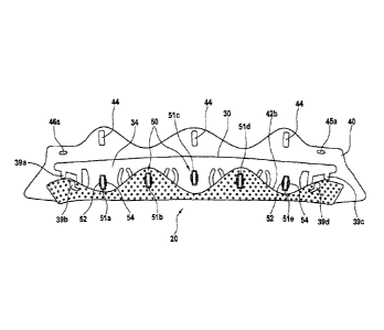
nated by 44'. The forehead band 20 comprises a strip-shaped support 30. Fig. 5
shows the support 30 of the forehead band 20 as a detail in a plan view on its
front
side. Fig. 6 shows the support 30 in a rear view. The support 30 is provided
with a
holder 50 for releasably fixing the forehead band 20 on a head band such as
the
head band 44'. The support 30 is covered by an overlay 40 made of a sweat-
absorbing material at least on its front side 32 visible in Fig. 5. However,
in the
embodiment of the forehead band 20 according to the invention shown in the
draw-
ings the overlay 40 is dimensioned so that it covers the support 30 on all
sides. This
support 30 covered by the overlay 40 on all sides is shown in a front view in
Fig. 1
and in a rear view in Fig. 2. In Fig. 3 the overlay 40 is shown halfway
uncoiled from
the support 30. Fig. 4 shows a complete uncoilment of the overlay 40 without
the
support 30.
The holder 50 comprises five tubular supporting connection pieces 51a, 51b,
51c,
51d and 51e which are integrally formed on a rear face 34 of the support 30
which is
the side of the support which can be brought in contact with the head band. In
Fig. 8
which shows a partial longitudinal sectional view of the support 30 along the
line
CA 02870046 2014-10-09
7
VIII-VIII in Fig. 5, and in Fig. 9, which shows the support 30 in of a cross
sectional
view along the line IX-IX in Fig. 5, the tubular supporting connection pieces
51a -
51e forming the holder 50 can be seen the best. The supporting connection
pieces
51a ¨ 51e are designed to non-positively or positively engage in openings of
the
head band. In the forehead band 20 shown as an embodiment here the supporting
connection pieces 51a ¨ 51e are designed to positively engage in openings of
the
head band. For this purpose, the supporting connection pieces 51a ¨ 51e are
respectively designed so as to be elastically resilient at their free end and
respec-
tively provided with at least one snap tab 52 and 54 protruding to the
outside. In the
embodiment of the forehead band 20 shown here each supporting connection piece
51a ¨ 51e comprises two snap tabs 52, 54 protruding to the outside. The
tubular
supporting connection pieces 51a ¨ 51e are rectangular in the cross section.
The
snap tabs 52, 54 are integrally formed on the opposing longitudinal sides of
the
cross section of each supporting connection piece. The tubular supporting
connec-
tion pieces 51a ¨ 51e have a height H respectively dimensioned so that, taking
into
account the thickness of the overlay 40 on the rear face 34, if the supporting
con-
nection pieces are inserted into openings complementary to their cross section
formed in the head band all the way to the stop, i.e. the support 30 abuts to
the head
band with the rear face 34 via the overlay 40, the snap tabs 52, 54 of each
support-
ing connection piece rest adjacent to the associated opening on the opposite
side of
the head band. This latched position of each supporting connection piece is
releas-
able by compressing it with the fingers or with a tool to the extent that the
snap tabs
52, 54 will be released from the front side of the head band so that the
support 30
can be pulled off the head band.
The support 30 is respectively provided with an air aperture 36a, 36b, 36c or
36d
between two of the supporting connection pieces 51a ¨ 51e. Each of these air
apertures 36a ¨ 36d is provided with a central bridge for reasons of stability
as can
be seen in Figs. 5 ¨ 7. Each of the air apertures 36a ¨ 36d can be aligned
with one
of the openings of the head band.
CA 02870046 2014-10-09
8
The overlay 40 comprises a textile blank shown in its entirety in Fig. 4. In
Fig. 4 it
can further be seen that the overlay 40 comprises longitudinal edges 42a, 42b
corrugated complementarily relative to each other. Corrugated complementarily
relative to each other means that each wave crest of the longitudinal edge 42a
is
opposed by a wave trough of the longitudinal edge 42b and vice versa. Each
wave
crest is provided with an opening 44 for receiving one of the supporting
connection
pieces 51a ¨ 51e. Further, the overlay 40 is provided with two holes 45a, 45b
or
46a, 46b on each end adjacent to the longitudinal edges 42a, 42b. The holder
50
comprises two pins 39a, 39b or 39c, 39d protruding into a recess 38a, 38b of
the
support 30 for fixing the ends of the corrugated longitudinal edges 42a, 42b
of the
overlay 40 at each end of the support 30. For fixation, the pins 39a, 39b are
inserted
into the holes 46a, 46b, and the pins 39c, 39d are inserted into the holes
45a, 45b of
the overlay 40 as can be seen in Fig. 2 showing the fixed state.
For fixing the overlay 40 on the support 30 it is buttoned to the supporting
connec-
tion pieces 51b to 51d at its longitudinal edge 42b according to the
illustration shown
in Fig. 3. The pins 39b and 39d of the support 30 are accommodated in the
holes
46b or 45b. Then the overlay 40 is brought in a position shown in in Fig. 2 in
which
the openings 44 are buttoned into the supporting connection pieces 51a, 51c
and
51d in the wave crests of the longitudinal edges 42a.
Finally, the pins 39a, 39c of the support 30 are inserted into the holes 46a
or 45a so
that the overlay 40 is fixed to the support 30 in the position shown in Fig.
2. In this
state the forehead band 20 can be put into the washing machine for cleaning.
However, the overlay 40 may also be removed from the support 30 and put into
the
washing machine as a separate part as shown in Fig. 4.
The overlay 40 consists of a textile material perforated by a plurality of
small open-
ings to render an air stream through the air apertures 36a ¨ 36d possible. In
addi-
lion, the textile material is selected so that it has a good sweat absorbing
capacity.
CA 02870046 2014-10-09
9
The support 30 is a flexible formed component made of a plastic material. In
this
way it is ensured that the support 30 can adapt to the curvature of the head
band
and that the tubular supporting connection pieces 51a ¨ 51e are, as such,
suffi-
ciently elastically flexible to render the engagement of the supporting
connection
pieces on the head band by means of the snap tabs 52, 54 possible.
CA 02870046 2014-10-09
List of Numerals
5 20 forehead band
20' forehead band
30 support
32 front side
34 rear face
10 36a air aperture
36b air aperture
36c air aperture
36d air aperture
38a recess
38b recess
40' interior fitting assembly
40 overlay
42' support cage
42a longitudinal edge
42b longitudinal edge
44 opening
44' head band
45a hole
45b hole
46' neck band
46a hole
46b hole
50 holder
51a supporting connection piece
51b supporting connection piece
51c supporting connection piece
CA 02870046 2014-10-09
11
51d supporting connection piece
52 snap tab
54 snap tab
56' joint
H height