Note: Descriptions are shown in the official language in which they were submitted.
CA 02870278 2016-09-14
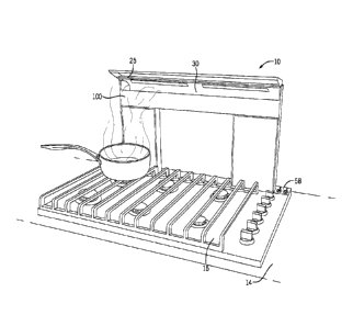
DOWNDRAFT SYSTEM
BACKGROUND
100011 The desire for ventilation solutions that do not significantly
interfere with
kitchen sight-lines drives consumer purchasing of many conventional downdraft
ventilation
systems. Many consumers for example desire a smaller kitchen footprint with
products that
do not obstruct, block, or close-off spaces within the smaller kitchen. At
least some of these
conventional downdraft systems can be disposed in a kitchen island or
peninsula and can raise
and lower from a position under a kitchen counter, which can result in
significant portions of
.. the hood being hidden when not in use
SUMMARY
[0002] Some embodiments of the invention provide a downdraft assembly
capable of
ventilating a cooktop including housing including a frame, a fluid box, and a
movement
assembly coupled to the housing. In some embodiments, the movement assembly
can include
a vertically moveable chimney coupled to the fluid box and the movement
assembly.
[0003] In some embodiments, the chimney can include an upper
horizontal member
and lower horizontal member. In some embodiments the chimney includes dual
fluid inlets
comprising an upper inlet and lower inlet.
[0003A] In some embodiments, the chimney includes a chimney housing, an
upper
horizontal member and a lower horizontal member. The upper horizontal member
cooperates
with the chimney housing to define an upper inlet, and the lower horizontal
member
cooperates with the chimney housing and the upper horizontal member to defme a
lower inlet.
[0004] In some embodiments, a first control panel can be coupled to
the housing and
.. configured and arranged to activate at least one function of the downdraft
assembly while
remaining substantially stationary when the chimney is moved by the movement
assembly.
[0005] Some embodiments include at least one illumination source
configured and
arranged to at least partially illuminate the cooktop. In some embodiments, a
visor can be
coupled to the downdraft assembly. In some embodiments, the visor can include
at least one
illumination source capable of at least partially illuminating the cooktop.
[0006] Some embodiments include a visor with an articulating top
capable of
articulation about a pivot point on the chimney. In some embodiments, an
articulation of
the articulating top of the visor about the pivot
1
CA 02870278 2014-11-06
point can at least partially alter the illumination of the cooktop. In some
other
embodiments, an articulation of the articulating top of the visor about the
pivot
point can at least partially control the flow of a cooking effluent into at
least one
fluid inlet.
[0007] Some embodiments include a second control panel coupled to the
chimney. In some embodiments, the second control panel is coupled to at least
one of the substantially horizontal member and the first vertical region and
the
second vertical region. In some embodiments, the second control panel is
vertically moveable with respect to the cooktop.
[0008] Some embodiments of the downdraft assembly include a
movement assembly with a belt-lift configuration. In some embodiments, the
belt-lift configuration can include at least one linear guide coupled to the
frame,
a motor including a gear box coupled to a drive shaft, and at least one drive
pulley coupled to the drive shaft. Some embodiments provide a drive belt
coupled to the drive pulley and at least one idler pulley. In some
embodiments,
the at least one drive pulley and the at least one idler pulley are coupled to
a
lateral side of the housing, and configured and arranged to at least partially
move
the chimney within the fluid box at least partially guided on the at least one
linear guide.
[0009] In some embodiments, the downdraft assembly includes a
pivotable bezel configured and arranged to pivot open to allow movement of the
chimney out of the fluid box and to pivot shut when substantially all of the
chimney is within the fluid box. Some embodiments of the downdraft assembly
comprise at least one ambient light illumination source, which in some
embodiments, is a night light coupled to the bezel.
[0010] In some embodiments, the downdraft assembly includes a fluid
box with inner walls including at least one curved wall including a
substantially
non-linear transition. In some embodiments, the fluid box is configured and
arranged to at least partially guide fluid into the fluid box from at least
one of the
fluid inlets. In some further embodiments, the at least one curved wall is
configured and arranged to at least partially guide fluid into the fluid box
from
substantially the width of the chimney. In some embodiments, the either one of
2
Attorney Docket 5978 192CA I
CA 02870278 2014-11-06
the fluid inlets includes a chimney intake opening of a size of about one to
about
two inches in vertical length.
[0011] Some embodiments include a downdraft system in which the
vertical height of the lower inlet and the vertical height of the upper inlet
are
independently adjustable based at least in part on effluent emitted from the
cooktop. In some other embodiments, the vertical height of the lower inlet and
the vertical height of the upper inlet are independently adjustable based at
least
in part on effluent drawn into either of the lower inlet or the upper inlet.
DESCRIPTION OF THE DRAWINGS
[0012] FIG. 1 is a perspective view of a portion of a downdraft system
according to one embodiment of the invention.
[0013] FIGS. 2A and 2B are diagrams depicting a conventional
downdraft system.
[0014] FIG. 3 is a series of diagrams depicting a movement assembly
according to some embodiments of the invention.
[0015] FIG. 4 is a series of diagrams depicting a movement assembly
according to some embodiments of the invention.
[0016] FIG. 5 is a series of diagrams depicting a movement assembly
according to some embodiments of the invention.
[0017] FIG. 6 is a series of diagrams depicting a movement assembly
according to some embodiments of the invention.
[0018] FIG. 7 is a series of diagrams depicting a movement assembly
according to some embodiments of the invention.
[0019] FIG. 8 is a series of diagrams depicting a movement assembly
according to some embodiments of the invention.
[0020] FIG. 9A is an image of a conventional downdraft system in
accordance with some embodiments of the invention.
[0021] FIG. 9B is an image of a downdraft system according to some
embodiments of the invention.
[0022] FIG. 10A is a diagram depicting varying chimney intake openings
to assess intake velocity.
3
Attorney Docket 5978 192CA I
CA 02870278 2014-11-06
[0023] FIG. 10B is a graph showing intake velocity with different
chimney intake openings.
[0024] FIG. 11 is a graph depicting fluid intake velocity testing
results.
[0025] FIG. 12 is a graph depicting fluid flow rate testing results.
[0026] FIG. 13 is a graph depicting auditory output testing results.
[0027] FIG. 14A is a diagram of inner walls of a chimney according to
some embodiments of the invention.
[0028] FIG. 14B is a graph of air velocity improvement according to
some embodiments of the invention.
[0029] FIG. 15 is multiple views of downdraft systems comprising a
visor according to some embodiments of the invention.
[0030] FIGS. 16A-D show various perspective views of downdraft
systems according to some embodiments of the invention.
[0031] FIG. 17 is a graph depicting fluid intake velocity testing
results.
[0032] FIG. 18 is a graph depicting fluid flow rate testing results.
[0033] FIG. 19 is a graph depicting auditory output testing results.
[0034] FIG. 20A is an image of portions of a conventional downdraft
system in accordance with some embodiments of the invention.
[0035] FIG. 20B is an image of portions of a downdraft system
according to some embodiments of the invention.
[0036] FIG. 21A is an image of portions of a conventional downdraft
system.
[0037] FIG. 21B is an image of portions of a downdraft system
according to some embodiments of the invention.
[0038] FIG. 21C is an image of portions of a downdraft system showing
an illumination system according to some embodiments of the invention.
[0039] FIGS. 21D-F show images of a lowered downdraft system
showing various embodiments of an ambient light illumination source according
to some embodiments of the invention.
[0040] FIG. 22A is an image of portions of a conventional downdraft
system.
[0041] FIG. 22B is an image of portions of a downdraft system
according to some embodiments of the invention.
4
Attorney Docket 5978 192CA1
CA 02870278 2014-11-06
[0042] FIG. 22C is an image of a downdraft system with trap door in
the
down position in accordance with some embodiments of the invention.
[0043] FIG. 22D is an image of a downdraft system with trap door in
the
up position in accordance with some embodiments of the invention.
[0044] FIGS. 23A-B show images of cooktop areas and downdraft
systems according to some embodiments of the invention.
[0045] FIG. 24 is a series of diagrams illustrating installation of a
downdraft system according to some embodiments of the invention.
[0046] FIG. 25 is a perspective view of a downdraft system according
to
some embodiments of the invention.
[0047] FIGS. 26A-26I illustrates a series of images of differently
configured chimneys according to some embodiments of the invention.
[0048] FIG. 27 is a series of images of a flexible ventilation
assembly
according to some embodiments of the invention.
I 5 [0049] FIGS. 28A-C illustrate various user interface controls
according
to some embodiments of the invention.
[0050] FIGS. 29A-E illustrates various views of a downdraft system
according to some embodiments of the invention.
[0051] FIGS. 30A-E illustrates various views of a downdraft system
according to some embodiments of the invention.
[0052] FIGS. 31A-E illustrates various views of a downdraft system
according to some embodiments of the invention.
[0053] FIGS. 32A-B illustrates various views of installation of a
downdraft system according to some embodiments of the invention.
[0054] FIG. 33 illustrates an assembly view of an fluid box of a
downdraft system according to some embodiments of the invention.
[0055] FIG. 34 illustrates an assembly view of a downdraft system
according to some embodiments of the invention.
[0056] FIGS. 35A-E illustrate side shadowgraphs of various prior-art
downdraft systems.
[0057] FIG. 36A illustrates a side shadowgraph of a Broan brand
downdraft system.
5
Attorney Docket 5978 192CA1
CA 02870278 2014-11-06
[0058] FIG. 36B illustrates a side shadowgraph of a Broane-Elite brand
downdraft system.
[0059] FIG. 36C illustrates a side shadowgraph of a Broane-Best brand
downdraft system.
[0060] FIG. 37 illustrates front perspective view of a dual inlet
downdraft system according to some embodiments of the invention.
[0061] FIG. 38 illustrates two side shadowgraphs of a dual inlet
downdraft system according to some embodiments of the invention.
[0062] FIGS. 39A-B provides a table including a 'time to boil' study
for
variations configurations of downdraft system 10 including dual inlets as
shown
in FIG. 37 in accordance with some embodiments of the invention.
DETAILED DESCRIPTION
[0063] Before any embodiments of the invention are explained in
detail,
it is to be understood that the invention is not limited in its application to
the
details of construction and the arrangement of components set forth in the
following description or illustrated in the following drawings. The invention
is
capable of other embodiments and of being practiced or of being carried out in
various ways. Also, it is to be understood that the phraseology and
terminology
used herein is for the purpose of description and should not be regarded as
limiting. The use of "including," "comprising," or "having" and variations
thereof herein is meant to encompass the items listed thereafter and
equivalents
thereof as well as additional items. Unless specified or limited otherwise,
the
terms "mounted," "connected," "supported," and "coupled" and variations
thereof are used broadly and encompass both direct and indirect mountings,
connections, supports, and couplings. Further, "connected" and "coupled" are
not restricted to physical or mechanical connections or couplings.
[0064] The following discussion is presented to enable a person
skilled
in the art to make and use embodiments of the invention. Various modifications
to the illustrated embodiments will be readily apparent to those skilled in
the art,
and the generic principles herein can be applied to other embodiments and
applications without departing from embodiments of the invention. Thus,
embodiments of the invention are not intended to be limited to embodiments
6
Attorney Docket 5978 192CA1
CA 02870278 2014-11-06
shown, but are to be accorded the widest scope consistent with the principles
and
features disclosed herein. The following detailed description is to be read
with
reference to the figures, in which like elements in different figures have
like
reference numerals. The figures, which are not necessarily to scale, depict
.. selected embodiments and are not intended to limit the scope of embodiments
of
the invention. Skilled artisans will recognize the examples provided herein
have
many useful alternatives that fall within the scope of embodiments of the
invention.
[0065] FIG. 1 illustrates a portion of downdraft system 10 according
to
one embodiment of the invention. The downdraft system 10 can include a
vertically moveable chimney 100 comprising a substantially horizontal member
coupled to a first vertical region 18a and a second vertical region 18b. In
some embodiments, the downdraft system 10 can also include a fluid box 150
(see for example FIG. 2A), a movement assembly (not shown in FIG. 1, but
15 shown as 400 in FIG. 4), and one or more fluid outlets 30. As shown in
FIG. 1,
in some embodiments of the invention, the downdraft system 10 can be installed
adjacent to a cooking area 14 (e.g., in a kitchen) and positioned adjacent to
and/or coupled with a cooktop 15. For example, in some embodiments, the
downdraft system 10 can be installed immediately adjacent to a cooktop 15, as
20 .. shown in FIG. 1. Furthermore, in some embodiments, as discussed in
greater
detail below, at least some portions of the downdraft system 10 (e.g., the
fluid
box 150, the movement assembly 400, and/or the fluid outlets 30, etc.) can be
installed substantially or completely under a counter surface 17, and coupled
to
the fluid box housing 152. In other embodiments, the downdraft system 10 can
be installed and/or used in other portions of a home or other structure. For
example, in some embodiments, the downdraft system 10 can be used in a
workshop or any other area that could require ventilation (e.g., a laundry, a
basement, a bathroom, etc.). Accordingly, although future description includes
details of the downdraft system 10 installed in a kitchen area (e.g., adjacent
to a
cooktop 15), this description is not intended to limit the scope of this
disclosure
to kitchen or cooking-related applications.
[0066] In some embodiments, the downdraft system 10 can operate in a
manner at least partially similar to a conventional downdraft system 11. In
some
7
Attorney Docket 5978 192CA I
CA 02870278 2014-11-06
embodiments, when the downdraft system 10 is in an inactive state, the chimney
100 can be in a substantially or completely lowered position. For example, as
shown in FIG. 3, the chimney 100 can be lowered so that a top portion 110 of
the chimney 100 is substantially flush with or lower than the counter surface
17
(shown in FIG. 1). As a result, when in an inactive state, most or
substantially all
the chimney 100 can be located under the counter surface 17 and not visible or
less visible to a user (i.e., providing a pleasant aesthetic experience).
[0067] In some embodiments, in order to exhaust at least a portion of
cooking effluent and other fluids produced during a cooking episode, the
movement assembly (shown as 300 in FIG. 3 and 400 in FIG. 4 for example) can
be activated (e.g., manually or automatically) to move the chimney 100. For
example, upon activation of the movement assembly 300, 400, the chimney can
be raised above the counter surface 17 so that an inlet 30 of the chimney 100
can
be in fluid communication with the local environment. In some embodiments,
the fluid box 150 can comprise one or more conventional ventilation assemblies
(for example, conventional fans or other devices configured to move fluids,
such
as air). Moreover, in some embodiments, the downdraft system 10 can comprise
a fluid path leading from the inlet 30, through the fluid box 150 and the
ventilation assembly, and out of the downdraft system 10 via conventional
fluid
outlets (not shown). In some further embodiments, the downdraft system 10 can
include one ore more flexible ventilation assemblies (such as for example cube-
like module 13 shown in FIG. 27, and described in more detail below).
[0068] In some embodiments, a ventilation assembly (including for
example one or more modules 13) can be activated (e.g., manually or
automatically) to generate a fluid flow to exhaust cooking effluent or other
fluids. For example, in some embodiments, the ventilation assembly 13 can
generate fluid flow from the inlet 30 (i.e., leading to fluid entering the
fluid path)
through portions of the downdraft system 10 (for example, the fluid box 150).
At
least a portion of the fluid can exit the downdraft system 10 via the one or
more
conventional fluid outlets. For example, the fluid outlets can be in fluid
communication with a conventional ventilation network of the structure into
which the downdraft system 10 is installed or can be directly coupled to an
exhaust that can direct the exhausted effluent to a desired location (e.g.,
out of
8
Attorney Docket 5978 192CA1
CA 02870278 2014-11-06
structure, out of the local environment, through a toe-kick of the counter,
etc.).
Moreover, in some embodiments, the downdraft system 10 can comprise one or
more conventional filters disposed along the fluid path to remove at least
some
portions of the effluent that may be desirable not to exhaust through the
fluid
outlets.
[0069] In some further embodiments, the downdraft system 10 can
include more than one inlet 30. For example, in some embodiments, the
downdraft system 10 can include an upper inlet 29a and a lower inlet 29b. In
some other embodiments, the inlet 30 can comprise more than one inlet. For
example, in some embodiments, the inlet 30 can comprise an upper inlet 29a and
a lower inlet 29b.
[0070] As shown in FIGS. 1 and 2, and as previously mentioned, some
portions of both conventional downdraft systems 11 and downdraft systems 10
according to some embodiments of the invention can be installed under a
counter
surface 17 and adjacent to a cooktop 15 and/or a conventional range oven. As
shown in FIGS. 2A and 2B however, configurations of some conventional
downdraft systems 11 can create limitations on areas and/or spaces into which
users can install conventional downdraft systems 11. For example, some
conventional downdraft systems can comprise a chimney 220 including a
relatively small depth (e.g., approximately two to three inches), as shown in
FIG.
2A. However, other elements of the conventional downdraft system 11 that can
be installed under the counter surface 17 can comprise a greater depth. For
example, as shown in FIG. 2B, after installation of the conventional downdraft
system 11, the conventional fluid box 210 and the conventional movement
assembly 200 can comprise a greater depth than the chimney 220. As a result,
the conventional downdraft system 11 can occupy a significant amount of space
under the counter surface 17, which can prevent the installation of some or
all
conventionally-sized under-cabinet and/or slide-in range ovens. Moreover, as
shown in FIG. 2B, a height value of some of the conventional downdraft system
11 components can also limit the installation of some conventional cooktops 15
because of the downward space requirements of the cooktops 15 and the upward
height requirement of some of the conventional downdraft systems 11.
9
Attorney Docket 5978 192CAI
CA 02870278 2014-11-06
[0071] In some embodiments, the downdraft system 10 can comprise a
lesser depth relative to at least some conventional downdraft systems 11. As
shown in FIG. 3 (with some missing components for illustrative purposes), in
some embodiments, the downdraft system 10 can comprise a substantially or
completely uniform depth (e.g., about two inches). For example, in some
embodiments, the downdraft system 10 can comprise a substantially uniform
two-inch profile depth (e.g., the depth value of assembled elements of the
downdraft system 10 comprises about two inches) so that the system 10 does not
interfere with under-cabinet and/or slide-in range oven installation.
Moreover,
because conventional range ovens can be installed immediately adjacent to the
downdraft system 10, the auditory output of the movement assembly 300, 400
can be at least partially insulated by the range oven (e.g., the
conventionally
sized range oven can function as a sound absorber), which does not occur with
some conventional downdraft systems 11. For example, the movement assembly
in many conventional downdraft systems 11 can be generally exposed so that
during operations of the conventional downdraft assembly 11, the auditory
output can be significant so that some users would find it objectionable.
Accordingly, by insulating the movement assembly 300, 400 in the downdraft
system 10, the user's experience with the downdraft system 10 can be more
enjoyable because of the decreased auditory output.
[0072] As shown in FIGS. 3-8, in some embodiments, movement
assemblies 300, 400, 500, 600, 700, 800 can be configured and arranged to move
the chimney 100. In some embodiments, the movement assemblies 300, 400,
500, 600, 700, 800 can operate in a manner substantially similar to a
conventional downdraft system 11. For example, in some embodiments, the
movement assemblies 300, 400, 500, 600, 700, 800 can be activated (e.g.,
automatically or manually) to move the chimney 100. In some embodiments, at
least one of the movement assemblies 300, 400, 500, 600, 700, 800 can be
configured and arranged to raise and/or lower the chimney (e.g., function as a
telescoping mechanism). For example, as shown in FIG. 3, when activated,
during operation of the downdraft system 10, the movement assembly 300 can
raise the chimney 100 so that the chimney 100 can exhaust at least a portion
of
cooking effluent created by a cooking episode. In some embodiments, at or near
Attorney Docket 5978 192CA1
CA 02870278 2014-11-06
an end of the cooking episode, the movement assembly 300 can be activated to
lower the chimney 100 so that a top of the chimney 110 is at or below the
surface of the counter surface 17(e.g., substantially flush with, or below the
counter surface level). In other embodiments, the movement assembly 300, 400
can be configured and arranged to move the chimney in other directions (e.g.,
side-to-side, diagonally, etc.). Moreover, as described in further detail
below, the
movement assembly 400 can comprise a plurality of different configurations.
[0073] In some embodiments, the movement assembly 300 can comprise
a pulley-lift configuration 305. As shown in FIG. 3, in some embodiments, the
movement assembly 300 can comprise a motor 307 (e.g., a direct current
brushed gear motor), a plurality of pulleys 310, and at least one spool pulley
320
coupled to the motor 307. Moreover, in some embodiments, the movement
assembly 300 can comprise one or more cables 330, as shown in FIG. 3.
Additionally, in some embodiments, the downdraft system 10 can comprise one
or more guides (for example, linear guides 460 as shown in FIG. 4) that can be
configured and arranged to assist in positioning (guiding) of the chimney 100
during movement assembly 400 activity.
[0074] In some embodiments, the pulley-lift configuration 305 of the
movement assembly 300 can enable the chimney 100 to move during operations
of the downdraft system 10. For example, as shown in FIG. 3, the motor 307 can
be disposed in a generally lower portion of the downdraft system 10 (e.g.,
under
the counter surface level adjacent to the one or more conventional fluid
outlets)
and can be immediately adjacent and/or coupled to the spool pulley 320.
Although depicted as generally central with respect to the flow path, the
motor
307 can be positioned elsewhere within the downdraft system 10 to reduce any
impact of fluid flow through the fluid path. In some embodiments, one or more
pulleys 310, 320 can be coupled to a support structure of the downdraft system
10 (e.g., a downdraft system frame 303) and other pulleys can be coupled to a
lower portion of the chimney 100. The spool pulley 320 can be coupled to the
support structure 303 adjacent to the motor 307. In some embodiments, a first
end of the cable 330 can be coupled to the spool pulley 320 and a second end
of
the cable 330 can be coupled to a portion of the support structure at an
opposite
side of the downdraft system 10, as shown in FIG. 3. In some embodiments, the
11
Attorney Docket 5978 192CA I
CA 02870278 2014-11-06
cable can be moveably positioned through the plurality of pulleys 310 and
anchored by the spool pulley 320 and the support structure 303.
100751 Moreover, in some embodiments, if the motor 307 is oriented in
a
substantially horizontal orientation, as shown in FIG. 3, gears 325 (e.g.,
bevel
gears) can be coupled the motor 307 and/or the spool gear 327. As a result,
activation of the motor 307 can translate to movement of the spool gear 327
because of the gear-gear (325 and 327) interaction, as shown in FIG. 3. In
some
embodiments, as the motor 307 moves the spool pulley 320, the spool pulley 320
can rotate. Because the first end of the cable 330 is coupled to the spool
pulley
320, as the pulley rotates, the cable 330 can begin to wind on the spool
pulley
320. For example, as shown in FIG. 3, because of the cable's positioning
through the plurality of pulleys 310 and being positioned along a lower
portion
of the chimney 100, as the spool pulley 320 winds greater amounts of cable 330
(i.e., because of the motor 307 moving the spool pulley 320), the cable 330
can
comprise greater amounts of tension and a shorter length. As a result, as the
cable 330 comprises a shorter length, the chimney 100 can be driven upward, as
shown in FIG. 3. In some embodiments, once the chimney 100 is fully extended
from the counter surface 17, the motor 307 can be locked or otherwise fixed in
position to retain the chimney 100 in a raised position. When the user no
longer
needs the downdraft system 10, the motor 307 can move the pulley 320 in a
reverse direction, can become deactivated so that the weight of the chimney
100
causes the cable 330 to unwind from the spool pulley 320, and/or the motor 307
can output a lesser amount of torque so that the cable 330 slowly unwinds to
lower the chimney 100. Moreover, in some embodiments, guides (for example
guides 460 in FIG. 4) can aid in preventing racking or other damage to the
chimney 100 as it is raised and lowered (i.e., the guides 460 can function to
direct the chimney 100 as it moves).
100761 In some embodiments, the movement assembly 400 can comprise
a belt-lift configuration 405 installed within a fluid box housing 152, as
shown in
FIG. 4. For example, in some embodiments, the movement assembly 400 can
comprise a motor 407 (e.g., a direct current brushed gear motor), a plurality
of
pulleys 410, one or more guides (e.g., linear guides 460), and a drive shaft
430
coupled to the motor 407 and/or one or more of the pulleys 410. In some
12
Attorney Docket 5978 192CA I
CA 02870278 2014-11-06
embodiments, as shown in FIG. 4, one or more belts 450 can be coupled to
and/or supported by the pulleys 410. In some embodiments, one or more belt
clamps 490 can be coupled to the chimney 100 and the belts 450. In some
embodiments, the chimney 100 can be at least partially moved within the fluid
box 150. In some embodiments, a conventional control system can control the
motor 407 to rotate the drive shaft 430 to drive the belts 450 causing at
least
partial movement of the chimney 100 via the coupling of the one or more belt
clamps 490. In some embodiments, the movement of the chimney 100 is guided
substantially by the one or more guides 460.
[0077] Further, as shown in FIG. 4, in some embodiments, one or more
of the pulleys 410 can be positioned at or adjacent to corners of the support
structure 403 under the counter surface 17. By way of example only, pulleys
410 can be positioned immediately adjacent to the two bottom comers of the
downdraft system 400 and two pulleys 410 can be positioned substantially
adjacent to upper corners of the downdraft system 400 (FIG. 4 shows a partial
view of the downdraft system 400 showing upper and lower corners on one side,
including a first lateral side 404, and it can be appreciated by one of
ordinary
skill in the art that the upper and lower corners on the other lateral side
can each
house a pulley 410 substantially identical to the pulleys 410 shown on the
first
lateral side 404). In some embodiments, the belts 450 can be coupled to
pulleys
410 on the same side of the downdraft system 400. By way of example, in some
embodiments, a first belt 450 can be coupled to and disposed between the
pulleys 410 on a first lateral side 404 of the downdraft system 400, and a
second
substantially identical belt 450 (not shown in the partial perspective view of
FIG.
4) can be coupled to and disposed between substantially identical pulleys 410
on
a second lateral side of the downdraft system 400 (i.e. the opposite side to
the
first lateral side 404). Moreover, in some embodiments, by placing the pulleys
410 at the lateral edges of the downdraft system 400, the pulleys 410 can be
positioned outside of the fluid path so that the fluid flow is not disturbed
by the
presence of the pulleys 410.
[0078] In some embodiments, movement of the motor 407 can be used to
at least partially move (e.g., raise and/or lower) the chimney 100. As shown
in
FIG. 4, the motor 407 can be coupled to the downdraft system 400 in a position
13
Attorney Docket 5978 192CA1
CA 02870278 2014-11-06
substantially adjacent to the drive shaft 430. For example, in some
embodiments,
the motor 407 and the drive shaft 430 can each comprise a gear (e.g., a spur
gear,
as shown in FIG. 4) so that motor 407 output (e.g., torque) is transferred
from
the motor 407 to the gear on the drive shaft. In some embodiments, in lieu of
gear, the motor 407 and drive shaft 430 can be coupled together via a belt
drive
450 to reduce auditory output. The drive shaft 430 can transfer the motor 407
output to the pulleys 410 to which the drive shaft 430 is coupled. For
example,
in some embodiments, the movement of the drive shaft 430 can cause movement
of the pulleys 410, leading to movement of the belts 450 and the belt clamps
supporting the chimney 100.
[0079] As shown in FIG. 4, the belt clamps 490 can be positioned so
that
lower portions of the chimney 100 (e.g., lower corners of the chimney) are
received within and supported by the belt clamps 490. In some embodiments, the
chimney 100 can be attached to the belt clamps 490, and in other embodiments,
the chimney 100 can rest on or float on the belt clamps 490. For example, by
floating or resting on the belt clamps 490, the chimney 100 can avoid being
pulled downward directly when it is being lowered (i.e., the belt clamps 490
are
pulled and the chimney 100 moves with the belt clamps 490). Accordingly, in
some embodiments, motor 407 movement can be translated to the pulleys 410
via the drive shaft 430. Moreover, in some embodiments, pulley 410 movement
can cause the belt clamps 490 to move (e.g., raise or lower), which can cause
raising and lowering of the chimney 100. Additionally, the guides 460 can be
coupled to the lateral walls (first lateral wall 404 and the opposite lateral
wall) of
the downdraft system 10 and the chimney 100 so that they can aid in preventing
.. racking or other damage to the chimney 100 as it is raised and lowered
(i.e., the
guides 460 can function to direct the chimney 100 as it moves). When the user
no longer needs the downdraft system 10, the motor 407 can move the drive
shaft 430 in a reverse direction, can become deactivated so that the weight of
the
chimney 100 causes the belt clamps 490 and belts 450 to move downward,
and/or the motor 407 can output a lesser amount of torque so that the belts
450
slowly move to lower the chimney 100.
[0080] As mentioned earlier, because conventional range ovens can be
installed immediately adjacent to the downdraft system 10, the auditory output
14
Attorney Docket 5978 192CA I
CA 02870278 2014-11-06
of the movement assembly 400 can be at least partially insulated by the range
oven (e.g., the conventionally sized range oven can function as a sound
absorber). Accordingly, by insulating the movement assembly 400 in the
downdraft system 10, the user's experience with the downdraft system 10 can be
more enjoyable because of the decreased auditory output. For example, in some
embodiments, the downdraft system 10 can comprise a movement assembly 400
that includes a shroud 408 at least partially enclosing one or more moving
components of the movement assembly 400. For example, as shown in FIG. 4,
the movement assembly 400 can includes a shroud 408 at least partially
enclosing at least the motor 407 and the gearbox 420 (i.e. components that may
cause a substantial portion of the noise emitted by the movement assembly
400).
In some embodiments the shroud 408 can reduce the sound emanating from the
motor 407. In some other embodiments, further conventional sound insulation
can be added to the shroud 408 to further reduce the sound emanating from the
motor 407. For example, in some embodiments, a conventional sound insulation
material can be added to the inside of the shroud 408, the outside of the
shroud
408, or both. In some other embodiments, a conventional sound insulation
material can be added to the inside of the frame support 403 of the fluid box
housing 152. For example, in some embodiments, a conventional sound
insulation material can be added to a region of the drive belt 450 and pulleys
410. In some other embodiments, a conventional sound insulation material can
be added to substantially the entire inner surfaces of the fluid box housing
152
including the frame support 403 and lateral sides (404 and opposite lateral
side)
of the movement assembly 400.
[0081] In some embodiments, the movement assembly 500 can comprise
a rack-and-pinion configuration 505 (as shown for example in FIG. 5). For
example, in some embodiments, the rack-and-pinion configured movement
assembly 500 can operate as a substantially conventional rack and pinion drive
system. As shown in FIG. 5, in some embodiments, the rack-and-pinion
configured movement assembly 500 can comprise a motor 507 (e.g., a direct
current brushed gear motor), at least one rack 523 comprising a plurality of
teeth
530, and at least one pinion 525. For example, in some embodiments, the motor
507 can be coupled to the chimney 100 and upon activation, can transfer output
Attorney Docket 5978 192CA I
CA 02870278 2014-11-06
to one or more pinions 525. In some embodiments, the motor 507 can be
oriented in a substantially horizontal manner, as shown in FIG. 5. In some
embodiments, the motor 507 can be oriented in any other manner (e.g.,
vertical,
diagonal, etc.). As shown in FIG. 5, in some embodiments, the racks 523 can be
coupled to lateral sides of the downdraft system support structure (i.e., the
frame
503) and can each comprise a plurality of teeth 530. The motor 507 and pinions
525 can be positioned so that the teeth 530 of the racks 523 can engage a
plurality of teeth 527 on the pinions 525. As a result, upon activation of the
motor 507, torque can be transferred to the pinions (e.g., two pinions 525
engaging two racks 523 at the lateral edges of the downdraft system support
structure 503), which can begin to rotate. Moreover, because of the engagement
of the pinion teeth 527 and the rack teeth 530 and the motor 507 being coupled
to the chimney 100, the motor 507 output can drive movement of the chimney
100 (e.g., raising and lowering the chimney). In some embodiments, the
downdraft system 10 can comprise a single, substantially medially positioned
rack 523 to reduce the materials necessary for operation of the downdraft
system
10.
[0082] In some embodiments, the movement assembly 600 can comprise
a scissor-lift configuration 605, as shown in FIG. 6. In some embodiments, the
movement assembly 600 can comprise a motor 607 (e.g., a direct current
brushed gear motor), a conventional lead screw, and a conventional scissor
mechanism. For example, the lower portion of the chimney 100 can be coupled
to and/or supported by a first scissor lift support 610 and a second scissor
lift
support 612 can be coupled to a lower portion of the downdraft assembly
support structure 603. In some embodiments, the scissor mechanism 605 can be
positioned to provide as little to no blockage of the fluid flow path (e.g.,
positioned against a wall of the support structure 603).
10083] In some embodiments, the scissor-lift configured movement
assembly 600 can operate in a manner substantially similar to a conventional
scissor lift assembly. For example, activation of the motor 607 (e.g.,
manually or
automatically) can transfer motor 607 output to the lead screw 601. As a
result,
the rotational movement of the lead screw 601 can be translated to linear
movement of the scissor mechanism 605 to raise and lower the chimney 100
16
Attorney Docket 5978 192CA1
CA 02870278 2014-11-06
(e.g., in a manner substantially similar to a conventional scissor lift
assembly).
As a result, the chimney 100 can move to enable use of the downdrall system 10
and the scissor-lift configuration 605 can enable relatively minimal
interruption
of fluid flow in the fluid path. Moreover, in some embodiments, obstruction of
fluid flow can be further minimized by positioning the motor 607 in a
relatively
central position.
[0084] As shown in FIG. 7, in some embodiments, the movement
assembly 700 can comprise a different lead-screw configuration 705. In some
embodiments, the movement assembly 700 can comprise a motor 707 (e.g., a
direct current brushed gear motor), at least one lead screw 701, and a timing
belt
710 being coupled to the motor 707 and configured to transfer motor output
from the motor 707 to the lead screws 701, as shown in FIG. 7. In some
embodiments, the lead screws 701 can be coupled to the chimney 100 at a
position substantially adjacent to the lateral edges of the chimney 100. As a
result, in some embodiments, activation of the motor 707 can lead to motor 707
output being transferred to the timing belt 710. In some embodiments, the
timing
belt 710 can be coupled to the lead screws 701 coupled to the chimney 100.
Accordingly, the rotational movement of the timing belt 710 can be translated
to
linear movement of the lead screws 701 and the chimney 100. In some
embodiments, the translation of the movement of the timing belt 705 can be
translated to telescoping movement of the chimney 100 resulting in raising and
lowering of the chimney 100, as desired by the user.
[0085] In some embodiments, the movement assembly 800 can comprise
a hydraulic-lift configuration 805. As shown in FIG. 8, in some embodiments,
the movement assembly 800 can comprise a lift piston 810, at least one pump
815, and a plurality of slides 820. In some embodiments, the pump 815 can be
positioned substantially adjacent to the lift piston 810, as shown in FIG. 8.
In
some embodiments, the pump 815 can be positioned elsewhere remote from the
lift piston 810, but still in fluid communication with the lift piston 810.
For
example, the pump 815 can circulate a hydraulic fluid (e.g., air, oil, point-
of-use
water, etc.) to and from the lift piston 810 in order to provide movement.
Moreover, in some embodiments, the lift piston 810 can comprise a conventional
dual-stage configuration, and in other embodiments, the lift piston 810 can
17
Attorney Docket 5978 192CA1
CA 02870278 2014-11-06
comprise other configurations (e.g., single stage). In some embodiments, the
hydraulic-lift configured movement assembly 800 can operate in a manner
substantially similar to a conventional hydraulic lift. For example, in some
embodiments, a first end 810a of the lift piston 810 can be coupled to the
lower
portion of the chimney 100 and a second end 810b of the lift piston 810 can be
coupled to a secure location (e.g., a floor of a cabinet, a floor of the
kitchen or
other room, etc.). Moreover, in some embodiments, the slides 820 can be
coupled to the chimney 100 and engaged with guide features (for example,
guides 460 shown in FIG. 4) that can be coupled to a wall of the downdraft
system support structure 803. As a result, the user can activate the pump 815
(e.g., manually or automatically) so that the pump 815 can move at least a
portion of a conventional hydraulic fluid into the lift piston 810 from the
pump
815. The hydraulic fluid can cause the lift piston 810 to linearly expand,
which
can cause vertical movement of the chimney 100. In some embodiments, the
user can deactivate the pump 815 when the downdraft system 10 is no longer
needed so that at least a portion of the hydraulic fluid returns to the pump
815 or
another location (e.g., a bladder, a tank, etc.) so that the chimney 100 can
be
lowered. In some embodiments, the slides 820 can function to retain the
chimney
100 along a substantially linear path as it moves.
[0086] Although multiple movement assembly configurations have been
mentioned above, the movement assembly can comprise other configurations.
For example, the movement assembly can comprise a conventional
electromagnetic configuration (e.g., substantially similar to a solenoid-like
configuration), or any other configuration that can function to move the
chimney
100.
[0087] FIG. 9A shows an image of a conventional downdraft system
with a downdraft systems that can vertically extend from a counter surface
level
adjacent to a cooktop a distance of less than about ten inches (shown as 905
in
FIG. 9A). As a result of this vertical height, many conventional downdraft
systems can only capture an average amount of effluent from lower- profile
cooking vessels immediately adjacent to the conventional system's inlet (i.e.,
the
conventional system can only capture effluent from lower-profile pans on back
cooktop burners and will not adequately exhaust effluent from higher-profile
18
Attorney Docket 5978 192CA I
CA 02870278 2014-11-06
pots and pans or effluent generated from more distal cooktop burners).
Further,
as shown in FIGS. 35A-E illustrating side shadowgraphs of various prior-art
downdraft systems 3500, 3510, 3520, 3530 and 3540, an effluent 3590 can
include an effluent flow region 3590b, influenced by an air-draw into a fluid
inlet, however the effluent 3590 also includes an effluent flow region 3590a
comprising effluent 3590 moving away from the conventional downdraft system,
no longer capable of being drawn into a fluid inlet (i.e. moving to region
3590b).
Similarly, FIG. 36A illustrates a side shadowgraph of a Broan brand downdraft
system 3600, FIG. 36B illustrates a side shadowgraph of a Broan -Elite brand
downdraft system 3610, and FIG. 36C illustrates a side shadowgraph of a
Broan -Best brand downdraft system 3620. As shown in the shadowgraphs of
FIGS. 36A-C, the downdraft systems 3600, 3610, and 3620 demonstrate effluent
regions 3590a and 3590b, indicative of a failure to fully capture the effluent
3590.
[0088] BROAN and BROAN BEST are registered trademarks of
Broan-NuTone LLC, 926 West State Street, Hartford, Wisconsin 53027.
[0089] In some embodiments, the downdraft system 10 can be
configured and arranged to more successfully capture cooking effluent and
other
fluids relative to some conventional downdraft systems. For example, in some
embodiments, as shown in FIG. 9B, the chimney 100 can vertically extend a
greater distance (shown as 950) than the chimney of at least some conventional
systems. As a result, the downdraft system 10 can exhaust effluent and other
fluids from cooking vessels adjacent to and/or distal from the chimney 100,
leading to an improved cooking episode experience.
[0090] In some further embodiments, effluent capture efficiency can be
further improved using multiple fluid inlets. As discussed earlier, in some
embodiments, the downdraft system can include dual inlets comprising an upper
inlet 29a and a lower inlet 29b. In some other embodiments, the inlet 30 can
comprise an upper inlet 29a and a lower inlet 29b. For example, FIG. 37
illustrates front perspective view of a dual inlet downdraft system 10
according
to some embodiments of the invention. As shown, in some embodiments, the
downdraft system 10 includes dual inlets 29a, 29b. The chimney 100 includes an
upper horizontal member 21 coupled to an upper inlet 29a and a lower inlet
29b.
19
Attorney Docket 5978 192CA1
CA 02870278 2014-11-06
The chimney 100 also includes a lower horizontal member 22 coupled to the
lower inlet 29b and the cooktop 15.
[0091] In some embodiments, the dimensions of either the upper
horizontal member 21 or lower horizontal member 22 can be varied to comprise
a smaller or greater total vertical dimension. Moreover, in some embodiments,
the total vertical dimension of the either of the upper inlet 29a or the lower
inlet
29b can be varied to be smaller or greater than that illustrated in FIG. 37.
For
example, in some embodiments, the upper horizontal member 21 and the lower
horizontal member 22 can be varied to comprise a smaller or greater total
vertical dimension than shown in FIG. 37. In some embodiments, the total
vertical dimension of the upper inlet 29a and the lower inlet 29b can be
varied to
be smaller or greater than that illustrated in FIG. 37. In some other
embodiments,
the total vertical dimension of the upper horizontal member 21, the lower
horizontal member 22, the upper inlet 29a and the lower inlet 29b can be
varied
to be smaller or greater can be varied to comprise a smaller or greater total
vertical dimension than shown in FIG. 37.
[0092] In some embodiments, either one or both of the upper and lower
horizontal members 21, 22 can be independently vertically moveable with
respect to the chimney 100. For example, in some embodiments, the upper
horizontal member 21 can be moved vertically upwards or vertically
downwards. Further, in some embodiments, the lower horizontal member 22 can
be moved vertically upwards or vertically downwards.
[0093] In some embodiments, the total vertical dimension of the upper
inlet 29a can be modified by moving the upper horizontal member 21 upwards
(i.e., away from the cooktop 15) or downwards (i.e., towards the cooktop 15).
In
some further embodiments, the total vertical dimension of the lower inlet 29b
can be modified by moving either or both of the upper horizontal member 21 and
lower horizontal member 22 upwards (i.e., away from the cooktop 15) or
downwards (i.e., towards the cooktop 15). In some embodiments, when
modifying the total vertical height of the upper inlet 29a through the
movement
of the upper horizontal member 21, the lower horizontal member 22 can be
moved to maintain the total vertical height of the lower inlet 29b. In other
embodiments, the lower horizontal member 22 can remain stationary, and the
Attorney Docket 5978 192CA1
CA 02870278 2014-11-06
total vertical height of the lower inlet 29b can be increased as the total
vertical
height of the upper inlet 29a decreases.
[0094] In some embodiments, either the upper horizontal member 21 or
the lower horizontal member 22 or both may be actuated together or
independently by any one of the movement assemblies 300, 400, 500, 600, 700,
800 depicted in FIGS. 3-8.
[0095] FIG. 38 illustrates two side shadowgraphs of a dual inlet
downdraft system 10 according to some embodiments of the invention. As
shown, an effluent 3800 can comprise effluent flow regions 3800a
corresponding to the effluent 3800 being drawn into the upper inlet 29a, and
an
effluent flow region 3800b, corresponding to the effluent 3800 being drawn
into
the lower inlet 29b. As shown, the use of dual inlets 29a, 29b enables
substantially all the effluent 3800 to be captured.
[0096] The embodiments shown and described in FIGS. 37 and 38 can
comprise upper and lower horizontal members 21, 22 and upper and lower inlets
29a, 29b within an eighteen inch chimney 100. In some other embodiments, the
chimney 100 can be taller or smaller. For example, in some embodiments, the
chimney 100 height can be fifteen inches, whereas in other embodiments, the
chimney 100 can be twelve inches. Furthermore, in some embodiments as shown
and described, one or more of the upper and lower inlet 29a, 29h
configurations
can capture substantially all effluent 3800 while maintaining a cooking
efficiency substantially unaffected by the effluent 3800 flowing into either
of the
inlets 29a, 29b. FIGS. 39A-B provides a table 3900 including a 'time to boil'
study for various configurations of downdraft system 10 including dual inlets
as
shown in FIG. 37 in accordance with some embodiments of the invention. As
shown, for downdraft system 10 including dual inlets 29a and 29b, the time to
boil water is substantially unaffected.
[0097] In some embodiments, the distance that the chimney 100 can
extend from the counter surface 17 (i.e., vertical height) can vary. In some
.. embodiments, the chimney 100 can extend a maximum vertical height (e.g.,
about eighteen inches for example as described earlier), however, the user can
also select a vertical height less than the maximum distance. For example, the
movement assembly 400 and/or other portions of the downdraft system 10 can
21
Attorney Docket 5978 192CA1
CA 02870278 2014-11-06
be configured so that the chimney 100 can extend a pre-defined set of vertical
heights from the counter surface 17 (e.g., the downdraft system 10 can
comprise
one or more settings that reflect the desired vertical height from the counter
surface level 17, such as, six inches, ten inches, twelve inches, fifteen
inches,
.. etc.). In some embodiments, the user can select the predefined vertical
height so
that the chimney 100 extends from the counter surface 17 by the predetermined
vertical height rather than the maximum vertical height. Furthermore, in some
embodiments, the downdraft system 10 can be configured so that the vertical
height can be continuously variable (i.e. the vertical height as an infinite
range of
settings between the fully extended height and the starting position where the
chimney is substantially fully enclosed by the fluid box 150, and not extended
above the counter 17). For example, the user can activate the movement
assembly 400 to begin raising the chimney 100 and the user can deactivate the
movement assembly 400 when the chimney 100 reaches a desired vertical height
(e.g., any vertical height less than or equal to the maximum vertical height).
[0098] In some embodiments, at least some portions of the downdraft
system 10 can be configured for use with conventional residential cooktops 15.
For example, in some embodiments, the height of the chimney 100 can be
optimized to improve and/or maximize capture of cooking effluent originating
from cooking vessels on a conventional residential cooktop (e.g., a cooktop 15
comprising a conventional depth). Moreover, in some embodiments, the height
of the chimney 100 can also be configured to account for a conventional
distance
between an upper portion of the cooktop 15 (for instance the cooking surface)
and one or more cabinets disposed substantially adjacent to the chimney 100
(for
example, above an upper portion of the chimney 100).
[0100] Moreover, in some embodiments, the one or more fluid inlets 30
can be optimized to provide the greatest possible fluid intake velocity, while
not
significantly affecting fluid flow rate. By way of example only, as shown in
FIGS. 10A, downdraft systems 10 comprising a fluid inlet 30 and chimney
intake opening 31 with a vertical length of four inches, three inches, two
inches,
one inch, and one-half inch were tested to assess fluid intake velocity
relative to
fluid flow rate (e.g., to ensure a maximum fluid intake velocity while not
significantly impacting fluid flow rate). The downdraft systems 10 were tested
22
Attorney Docket 5978 192CA I
CA 02870278 2014-11-06
relative to some conventional downdraft systems (for example, see the data in
FIG. 10B as well as the data in FIGS. 11-12 comparing the Kenmore Elite 30
in FIGS. 11 and 12). Kenmore Elite is a registered trademark of KCD IP, LLC.
For example, as shown in FIGS. 10A, 10B, and 11, the results indicate that the
greater the vertical length of the chimney intake opening 31 of the fluid
inlet 30,
the lesser the fluid flow rate through the inlet 30, and vice versa. Moreover,
as
shown by the results in FIG. 12, although the fluid flow rate does not
fluctuate as
much as the fluid intake velocity based on inlet length of the chimney intake
opening 31, the graph illustrates that, generally, the greater the inlet 31
length,
the greater the fluid flow rate. Moreover, as shown in FIG. 13, the sound
output
by the downdraft system 10 can also increase with greater fluid inlet length
of
the chimney intake opening 31. Accordingly, based on an analysis of the
results,
a chimney intake opening 31 of a size of about one to two inches in vertical
length was selected because of the maximized fluid intake velocity with no
significant impact on the fluid flow rate.
[0101] In some embodiments, the downdraft system 10 can comprise
other elements that can enable improved fluid flow through the chimney 100 and
other portions of the system. For example, as shown in FIG. 14A, at least a
portion of one or more internal walls 125 that define some portions of the
fluid
path of the fluid inlet 30 can be configured to improve or optimize fluid flow
rate and fluid intake velocity. For example, FIG. 14B is a graph of air
velocity
improvement using a various configurations of the internal walls 125 shown in
FIG. 14A. As shown, in some embodiments, the internal walls 125 (e.g.,
positioned inside of the chimney 100 and substantially adjacent to the fluid
inlet
30) can comprise one or more angled, curved, and/or otherwise substantially
non-linear transitions 125a. For example, as shown in FIG. 14A, by configuring
areas of the inner walls 125 (e.g., configuring the walls with non-linear
features)
where fluid entering the inlets 30 transitions from a substantially horizontal
flow
to a substantially non-horizontal or vertical flow, the flow profile of the
downdraft system 10 can comprise a more laminar flow profile, which can lead
to fluids being pulled from an entire length and/or width of the inlet (i.e.,
relative
to some downdraft systems that comprise linear inner wall transitions 125a).
As
23
Attorney Docket 5978 192CA I
CA 02870278 2014-11-06
shown, in some embodiments, the entire length and/or width of the inlet can be
substantially equal to the width of the chimney 100.
101021 In some embodiments, the downdraft system 10 can comprise one
or more visors 25, as shown in FIGS. 15 and 16A-D. As shown, in some
embodiments, the visor 25 can be coupled to the chimney 100 so that when the
visor 25 comprises a closed or substantially close position, the visor 25 can
partially or completely obstruct the fluid inlet 30. In some embodiments, the
visor 25 can substantially control the flow of a cooking effluent. For
example, in
some embodiments, the visor 25 can substantially guide the flow of a cooking
effluent into one or more fluid inlets 30. Some embodiments include different
size, shape and position with respect to the cooktop 15 and the cooking area
14.
Some embodiments include a visor 25 with an angle with respect to the cooktop
and the cooking area 14. Some embodiments include a visor 25 with a shape
and position and angle to guide substantially all the cooking effluent from a
15 .. cooking area into the downdraft system 10.
[0103] In some embodiments, before and/or after the chimney 100
arrives at a fully raised position, the visor 25 can move from a substantially
or
completely closed position to an open position (e.g., the visor 25 can
comprise
an articulating top 26, as shown in FIG. 16A). For example, in some
embodiments, the visor 25 can pivot about a point so that at least a portion
of the
visor 25 moves from a position substantially parallel to a vertical axis of
the
chimney 100 to a position substantially perpendicular to the vertical axis of
the
chimney 100 (shown in FIG. 16A). Moreover, in some embodiments, the visor
can automatically move as a result of the chimney 100 reaching its maximum
25 height and/or the visor 25 can be manually moved as a result of a user
inputting
instructions for the visor 25 to move. In some embodiments, the visor 25 can
comprise multiple pivot points or articulations so that the visor 25 can move
to
the open position through multiple steps. In some embodiments, the visor 25
can
be configured and arranged so that when the visor 25 comprises the open
configuration, the visor 25 can aid in guiding cooking effluent and other
fluids
into the inlet 30 (e.g., the visor 25 can operate as a capture ledge), which
can at
least partially enhance fluid intake and exhaust.
24
Attorney Docket 5978 192CA1
CA 02870278 2014-11-06
[0104] In some embodiments, the visor can comprise alternative
configurations. As shown in FIG. 16B, the visor 25 can pivot about a point
below the top of the chimney (shown as pivot point 25a). For example, in some
embodiments, the visor 25 can comprise an articulating front panel
configuration
.. 23. The visor can move so that an upper portion of the visor (the
articulating
front panel configuration 23) moves outward from the chimney 100 to allow
fluid to enter the fluid inlet 30 (e.g., the visor 25 can move so that it
pivots in a
generally forward direction toward the cooktop). In other embodiments, the
visor
25 can be configured so that it pivots, articulates, or otherwise moves in any
direction (e.g., a combination of the top articulating visor and the
articulating
front panel configuration). Moreover, in some embodiments, the distance that
the visor 25 moves while pivoting between a substantially open and closed
position can be variable. For example, in some embodiments, the user can open
the visor 25 a distance less than a maximum distance to provide a more-
directed
fluid intake flow (e.g., the visor 25 can be moved to any position between the
open and closed positions).
[0105] As shown in FIG. 16C, in addition to, or in lieu of comprising
a
visor 25, in some embodiments, the chimney 100 can comprise a plurality of
substantially vertically arranged fluid inlets 30. In some embodiments, the
downdraft system 10 including the chimney 100 can comprise a perimeter
induction configuration. For example, in some embodiments, the chimney 100
can comprise a central region 19b and two central regions (18a, 18b) disposed
on
lateral sides of the central region 19b. Moreover, as shown in FIG. 16C, in
some
embodiments, a perimeter of an area (a perimeter region 19c) where the central
region 19b transitions to the column regions 18a, 18b can comprise a plurality
of
fluid inlets 30. For example, in some embodiments, in addition to or in lieu
of a
generally horizontally arranged fluid inlet 30 adjacent to a top of the
chimney,
the chimney 100 can comprise perimeter induction fluid inlets including
vertical
inlets 32a and horizontal inlets 32b at the upper region of the fluid box 150.
In
other embodiments, the perimeter induction fluid inlets 32a, 32b can comprise
any other configuration around the perimeter of an area 19c.
[0106] Further, in some embodiments, the configuration of the visor 25
can be optimized to provide the greatest possible fluid intake velocity, while
not
Attorney Docket 5978 192CA1
CA 02870278 2014-11-06
significantly affecting fluid flow rate. As shown in FIG. 17, the downdraft
system 10 comprising different configurations of the visor 25 can exhibit
different fluid intake velocities. For example, downdraft systems 10
comprising
a visor 25 that generally pivots in a forward direction can intake fluids at a
greater velocity than downdraft systems 10 without that configuration, as
shown
in FIG. 17. Moreover, as shown in FIG. 18, fluid flow rates for downdraft
systems 10 comprising a visor 25 can exceed the rates of other configurations.
Furthermore, as shown in FIG. 19, the auditory output can be substantially
similar among the different conditions. Accordingly, differently configured
downdraft systems 10, including different visor 25 configurations, can be used
to
meet different end user needs.
101071 In some embodiments, the chimney 100 can comprise multiple
configurations. For example, as shown in FIG. 20B, relative to a conventional
downdraft system shown in FIG. 20A, some embodiments of the invention can
provide for an improved functional structural configuration. For example, as
shown in FIG. 20A, some conventional configurations can comprise
configurations that can impede lines of sight when the chimney is fully
extended.
101081 In some embodiments of the invention, the central region of the
chimney 100 can comprise an open configuration. For example, as shown in
FIG. 20B, in some embodiments, the central region 19a can comprise an
aperture or other void or structure that can be substantially or completely
transparent. As a result, some lines of sight are not completely blocked,
which
can be an improvement over some conventional configurations (as depicted in
FIG. 20A for example). In some embodiments, the central region 19a can
comprise multiple configurations. For example, in some embodiments, the
central region 19a can comprise a material that is substantially translucent
or
transparent (e.g., glass or frosted glass) or can comprise an opaque material
(e.g.,
stainless steel). Moreover, in some embodiments, the central region 19a can
comprise the material covering only a portion of the central region 19a (e.g.,
a
piece of glass positioned between the column regions 18a, 18b that only
extends
a portion of a length of the central region 19a and couples to only a partial
length
of the perimeter region 19c).
26
Attorney Docket 5978 192CA I
CA 02870278 2014-11-06
[0109] In some embodiments, the chimney 100 can comprise an
illumination device 35. In some embodiments, the illumination device 35 can be
configured as a cooking surface task lighting device 35. In some embodiments,
the illumination device 35 can be function as a more effective illumination
system relative to some conventional downdraft systems. As shown in FIG. 21A,
some conventional downdraft systems can comprise illumination devices 35
positioned at a top of the chimney. The conventional illumination devices can
provide limited lighting for the adjacent cooking areas because of their
positioning at the chimney 100 and because the illumination devices are
generally directed upward, away from the cooking area.
[0110] In some embodiments, a downdraft system 10 can include the one
or more illumination devices 35 configured and arranged to provide lighting to
a
at least partially illuminate a cooktop 15. In some embodiments, the one or
more
illumination devices 35 can be configured and arranged to provide lighting to
an
area immediately adjacent to a cooktop 15. In some embodiments, at least one
illumination device 35 is coupled to a conventional control system (not
shown),
and at least one user interface 50 and at least one control panel 55, 58. In
some
embodiments, one or more illumination devices 35 provide fixed illumination
intensity to a cooktop 15. In some other embodiments, the illumination
intensity
of the illumination devices 35 can be varied to provide variable illumination
intensity to a cooktop 15. In some embodiments, the illumination devices 35
can
comprise one or more incandescent lamps. In other embodiments, the
illumination devices 35 can comprise at least one fluorescent lighting source,
or
one or more light-emitting diodes. In some embodiments, other lighting sources
can be used.
[0111] Some embodiments of the invention can provide improved
illumination capabilities relative to the conventional systems. As shown in
FIG.
2IB, in some embodiments, the illumination device 35 can be positioned at an
upper portion of the central region 19a (substantially coupled at the
perimeter
region 19c) so that at least a portion of the illumination radiated by the
illumination device 35 can be directed toward the cooking area 14. Moreover,
as
previously mentioned, the illumination provided by some embodiments of the
invention can be further enhanced because of the greater height of the
downdraft
27
Attorney Docket 5978 192CA I
CA 02870278 2014-11-06
system 10 (i.e. greater amounts of illumination can reach the cooking area 14
because of the greater height of the chimney 100). As shown in FIG. 21C which
illustrates an image of portions of a downdraft system 10 showing an
illumination system, in some embodiments, the illumination device 35 can be
positioned at an upper portion of the substantially horizontal member 20
(adjacent to the visor 25) so that at least a portion of the illumination
radiated by
the illumination device 35 can be directed toward the cooking area 14. Here
again, as previously mentioned, the illumination provided by some embodiments
of the invention can be further enhanced because of the greater height of the
downdraft system 10. Furthermore, as illustrated in FIG. 21C, in some
embodiments, the one or more illumination devices 35 can be angled so as to
direct a greater proportion of the emitted light to the cooktop 15. Moreover,
in
some embodiments, one or more of the illumination devices 35 can include a
lens 38 configured and arranged to focus a greater proportion of the emitted
light
to the cooktop 15. In some embodiments, one or more of the illumination
devices 35 can include a plurality of lenses 38. In some embodiments, one or
more of the illumination devices 35 can include a plurality of lenses 38
configured and arranged to focus a greater proportion of the emitted light in
substantially one direction. In some embodiments, one or more of the
illumination devices 35 can include a plurality of lenses 38 configured and
arranged to focus a greater proportion of the emitted light in a plurality of
directions. In some other embodiments, one or more of the illumination devices
35 can include a plurality of lenses 38 configured and arranged to focus a
greater
proportion of the emitted light to substantially one region of the cooktop 15.
In
some further embodiments, one or more of the illumination devices 35 can
include a plurality of lenses 38 configured and arranged to focus a greater
proportion of the emitted light in a plurality of regions of the cooktop 15.
Moreover, in some embodiments, the central region 19a can comprise one or
more illumination devices 35 that can illuminate the material positioned in
the
central region 19a. For example, in some embodiments, one or more glass
members can be positioned within or coupled to the central region 19a and the
illumination devices 35 (e.g., light-emitting diodes or any other conventional
illumination sources) can disperse at least some illumination toward the glass
so
28
Attorney Docket 5978 192CA I
CA 02870278 2014-11-06
that the glass is at least partially illuminated by the devices 35. Moreover,
in
some embodiments, the illumination devices 35 can be coupled to a portion of
the glass and/or the central region 19a (e.g., disposed around at least a
portion of
a periphery or edges of the glass). As a result, the illuminated glass pieces
can
.. provide task lighting and/or decorative lighting for the user. Moreover, in
some
embodiments, the glass can comprise a brand or logo marking that has been
positioned to be illuminated by the illumination provided by the illumination
device 35 (e.g., the brand or logo can be etched into a surface of the glass).
101121 FIGS. 21D-F shows images of a lowered downdraft system 10
showing various embodiments of an ambient light illumination source 34
according to some embodiments of the invention. As shown, in some
embodiments, the downdraft system 10 can provide an ambient illumination 34
to at least some portion of the cooktop 15 and a least some portion of the
cooking area 14. FIG. 21D for example shows a lowered downdraft system 10
showing an ambient light 34a configured and arranged to at least partially
illuminate a wall 16. FIG. 21E for example shows a lowered downdraft system
10 showing an ambient light 34b configured and arranged to at least partially
illuminate the cooktop 15. FIG. 2IF for example shows a lowered downdraft
system 10 showing an ambient light 34c that is configured and arranged as a
.. night light coupled with the bezel 27. In some other embodiments, the
downdraft
system 10 can include various alternative embodiments of an ambient light
illumination source 34. For example, some embodiments may include a
combination of one or more of the ambient light illumination source 34
embodiments illustrated in FIGS. 21D-F.
[0113] In some embodiments, the downdraft system 10 can comprise
other improvements relative to some conventional downdraft systems. As shown
in FIG. 22A, some conventional downdraft systems can comprise mounting
brackets that extend into the cooking area. These mounting brackets can be
important to retain the conventional downdraft system in position before,
during,
and after operations. By extending into the cooking area 14, the conventional
brackets can reduce available useful space and can be generally unsightly.
Conversely, in some embodiments of the invention, the downdraft system 10 can
comprise a bezel 27 that can be configured and arranged to couple to the
29
Attorney Docket 5978. 192CA1
CA 02870278 2014-11-06
downdraft system 10 on the counter surface level 17. As shown in FIG. 22B and
FIG. 22C, the bezel 27 can be coupled to the counter 17 so that when the
chimney 100 is not in use and is at least partially disposed under the counter
surface level 17, the bezel 27 can be pivoted, functioning as a "trap door"
that
can substantially or completely cover the top of the chimney 100 so that
chimney 100 is hidden from sight (see FIG. 22C). As shown in FIG. 22B, the
bezel 27 can comprise multiple configurations and can comprise a trap door 28
that can pivot in any one of a plurality of directions. FIG. 22D is an image
of a
downdraft system 10 with trap door 28 in the up position in accordance with
.. some embodiments of the invention. In some embodiments, the trap door 28
(bezel 27) can comprise stainless steel. In some further embodiments, the trap
door 28 (bezel 27) can comprise a painted metal. In some other embodiments,
the trap door 28 (bezel 27) can comprise a non-metal such as a glass. In some
other embodiments, trap door 28 (bezel 27) can comprise a material
substantially
identical to the cooktop 15.
[0114] According to some embodiments of the invention, the downdraft
system 10 can be used with different cooking arrangements. As shown in FIG.
23A, some cooking areas can be configured for a single cooking vessel, such as
a fifteen inch cooking module. In some embodiments, the downdraft system can
comprise a width (e.g., about fifteen inches wide) so that the downdraft
system
10 can be installed for use with cooking areas of different sizes. As a
result, the
downdraft system 10 of the appropriate size can be selected based on the
cooking area that needs ventilation. Moreover, in some embodiments, a pre-
existing cooking area can comprise a configuration that can preclude the use
of
some conventionally-sized downdraft systems. As shown in FIG. 23B, some
cooktops 15 can be installed immediately adjacent to a wall 16 or other
structure
so that a conventional downdraft system cannot fit in the space between the
wall
and the cooktop 15. In some embodiments, a downdraft system 10 comprising a
non-conventionally sized chimney (e.g., approximately eighteen to twenty
inches wide) can be installed immediately adjacent to a lateral side (shown as
the
region 15a of the cooktop 15) so that the cooktop 15 can be properly
ventilated,
without the need for the downdraft system 10 to be installed between the
Attorney Docket 5978 192CA I
CA 02870278 2014-11-06
cooktop 15 and the wall 16. As a result, downdraft systems of multiple widths
can enable use under multiple circumstances.
[0115] Moreover, as shown in FIG. 24, in some embodiments, the
downdraft system 10 can be installed between two or more cooktops 15. By way
of example only, in some embodiments, the downdraft system 10 can be
installed so that the chimney 100 can extend from the counter surface 17 at a
position between at least two cooking modules 15 (e.g., fifteen inch cooking
modules). In some embodiments, the chimney 100 can comprise two or more
visors 25 disposed on each side of the chimney 100 adjacent to the cooking
modules 15 disposed on opposite sides of the downdraft system 10. As a result,
in some embodiments, the visor 25 can be moved so that cooking effluent or
other fluids can be exhausted from one or both of the cooking modules 15. For
example, if a user is employing one of the cooking modules 15, the visor 25 on
the side of the chimney 100 adjacent to the active cooking module 15 can be at
least partially moved to enable intake of some or all cooking effluent.
Moreover,
in some embodiments, if both cooking modules 15 are being used, the visors 25
on the sides of the chimney 100 can be at least partially opened to enable
intake
of some or all cooking effluent.
[0116] As previously mentioned, in some embodiments, the chimney 100
can operate without a visor 25. Accordingly, in some embodiments, the chimney
100 can comprise an internal shutter or visor 25 within the fluid flow path
substantially adjacent to the one or more inlets 30. In some embodiments, the
internal shutter or visor can operate in a manner substantially similar to the
visor
(e.g., moving to enable fluid flow through the one or more inlets. For
25 example, if a user is employing one of the cooking modules 15, the
internal
shutter or visor 25 on the side of the chimney 100 adjacent to the active
cooking
module 15 can be at least partially moved to enable intake of some or all
cooking effluent. Moreover, in some embodiments, if both cooking modules 15
are being used, the internal shutter or visors 25 can be at least partially
opened to
enable intake of some or all cooking effluent.
[0117] In some embodiments, the downdraft system 10 can comprise one
or more control panels 55, 58. For example, as shown in FIG. 25, in some
embodiments, the chimney 100 can comprise a second control panel 55 (capable
31
Attorney Docket 5978 192CA1
CA 02870278 2014-11-06
of vertical movement with the chimney) and a first control panel 58 that can
be
coupled to or integral with the fluid box housing and with the bezel 27, and
which remains substantially stationary when the chimney is move vertcially. In
some embodiments, the first control panel 58 can comprise one or more buttons
or other control features 60 that a user can employ to raise and lower the
chimney 100, and in some embodiments, can include one or more indicators 59.
For example, before, after, or during a cooking episode, a user can actuate
the
button 60 to raise or lower the chimney 100 to ventilate some or all of the
effluent generated by the cooking episode. Also, in some embodiments, the
first
control panel 58 can comprise one or more illumination devices 35 that can
operate (e.g., automatically or manually) when the local area is devoid of
some
or all light (e.g., the illumination device of the first control panel 58 can
operate
as a night light). In some embodiments, the control panels 55, 58 can be
positioned to enable ease of use. For example, in some embodiments, the
control
panels 55, 58 can be positioned so that the user does not have to reach across
some or all of the cooktop 15 so that the risk potential injury to the user
(e.g.,
bums from cooking episodes) can be reduced or eliminated. Moreover, in some
embodiments, one of or both of the control panels 55, 58 can be voice
activated
and/or capable of communicating with a remote control unit (e.g., mobile or
stationary remote control unit) capable of being used by the user to control
downdraft system 10 operations.
[0118] In some embodiments, the second control panel 55 can comprise
buttons, dials, or other elements 60 coupled or integrated with the at least
some
portion of the chimney (for example, coupled to or integrated with the first
vertical region 18a, the second vertical region 18b, or the central region
19b). In
some embodiments, the second control panel 55 can comprise buttons, dials, or
other elements 60 that are configured and arranged to control the ventilation
and
illumination capabilities of the downdraft system 10. For example, in some
embodiments, the buttons 60 can comprise the ability to control the raising or
lowering of the chimney 100, the ventilation assembly (i.e., control
activation
and deactivation and/or multiple operational speeds of the ventilation
assembly),
the illumination systems 35, and can also provide feedback to the user. For
example, in some embodiments where the downdraft system 10 comprises a
32
Attorney Docket 5978 192CA1
CA 02870278 2014-11-06
conventional filter, the second control panel 55 can comprise one or more
indicators 56 that can provide an indication of whether the filter needs to be
cleaned and/or replaced. Moreover, in some embodiments, the second control
panel 55 can also include an indicator 56 reflecting the thermal conditions
adjacent to the chimney 100 (e.g., the indicator 56 can provide an indication
of
when too much thermal energy is detected). In some embodiments, the buttons
60 can comprise electromechanical switches, and in other embodiments, the
buttons, dials, or other elements can comprise rear-mounted capacitive
controls
that can be touch activated.
[0119] As shown in FIGS. 26A-I, in some embodiments, the downdraft
system 10 can comprise multiple exteriors and one or more common internal
components (e.g., fluid box, ventilation assembly, etc.). In some embodiments,
the downdraft system 10 including the chimney 100 can comprise a substantially
similar configuration internally (for example, the chimney housing 120 and
internal walls 125, 125a can be the same), whereas at least some external
components can be differently configured (including at least regions 18a, 18b,
19a or 19b) to provide chimneys to appeal to a wider group of end users. For
example, as shown in FIG. 26A-I, the chimney 100 can comprise one of a
plurality of configurations that can be configured to appeal to different end
users
(e.g., the different chimney 100 configurations can enable downdraft system
price points, brand differentiation, and/or price-point differentiation).
[0120] In some embodiments, the downdraft system 10 can comprise
conventional and/or alternative configurations. In some embodiments, the
downdraft system 10 can comprise a substantially conventional configuration
(for instance including the fluid box 150 and operable to generate fluid flow
through the one or more inlets 30), as previously mentioned. In some
embodiments, the downdraft system 10 can comprise alternative configurations.
For example, as shown in FIG. 27, in some embodiments, the downdraft system
10 can comprise a flexible and/or modular configuration capable of accepting a
variety of flexible ventilation systems (cube-like modules 13). In some
embodiments, the downdraft system 10 can comprise one or more cube-like
modules 13 that can be installed remotely relatively to other portions of the
downdraft system 10. For example, in some embodiments, the flexible
33
Attorney Docket 5978 192CA1
CA 02870278 2014-11-06
ventilation assembly modules 13 can be installed at any location within or
adjacent to the structure (e.g., an attic, a crawl space, another cabinet,
coupled to
an outer wall of the structure, etc.) and the modules 13 can be in fluid
communication with the other portions of the downdraft system 10. Moreover, in
some embodiments, the one or more components of the downdraft system 10
(for example, the flexible ventilation assembly modules 13) can be coupled to
an
outer wall of the downdraft system support (for example, the fluid box housing
152). Further, although depicted comprising a substantially cube-like
configuration that is about twelve inches in length and width, the flexible
ventilation assembly modules 13 can comprise other shapes, configurations,
and/or sizes that can be accommodated within or adjacent to the structure 12.
The flexible ventilation assembly modules 13 can accept many types of
conventional blower configurations (internal or external) with different
operating
parameters. When the conventional blower is attached to the system, a
conventional control system will recognize what specific type of blower is
attached through a conventional wire harness (pin configuration) or
conventional
logic on the control board (using for instance, current sensing, etc.). The
downdraft system 10 can then adapt and calibrate to the correct operating
parameters of the specific blower that is attached.
[0121] In some embodiments, at least some portions of the downdraft
system 10 (e.g., the fluid box 150 and/or the support structure 12) can
comprise
one or more duct knock-out panels 159. For example, in some embodiments,
some or all side panels of the support structure and/or the fluid box 150 can
comprise the duct knock-out panels 159. In some embodiments, the knock-out
panels 159 can be configured so that a user or installer can remove one or
more
of the knock-out panels 159 so that the flexible ventilation assembly module
13
can be fluidly connected to the downdraft system 10, regardless of where it is
positioned. As a result, the downdraft system 10 can be installed in a variety
of
locations and in a variety of configurations, which can enable a user to
employ
the downdraft system 10 in different ventilating applications.
[0122] As described earlier, in some embodiments, the downdraft system
10 can comprise one or more control panels 55, 58. FIG. 25 shows for example
that a first control panel 58 can be coupled to or integral with the bezel 27.
In
34
Attorney Docket 5978 192CA1
CA 02870278 2014-11-06
some embodiments, the first control panel 58 can comprise one or more buttons
or other control features 60 that a user can employ to raise and lower the
chimney 100. In some embodiments, the first control panel 58 can comprise
buttons, dials, or other elements 60 that are configured and arranged to
control
the ventilation and illumination capabilities of the downdraft system 10. In
some
embodiments, the one or more control panels 55, 58 can comprise
configurations, including various configurations of the buttons 60. For
example,
FIGS. 28A-C illustrate various user interface controls according to some
embodiments of the invention. As shown in FIG. 28A, some embodiments of the
invention include at least one user interface 50 including a first control
panel 58.
In some embodiments, the first control panel 58 can include one or more
switches, buttons or other control features 60 located substantially on the
user
interface 50. In some embodiments, the switches or buttons 60 can comprise the
ability to control a conventional ventilation assembly (i.e., control
activation and
deactivation and/or multiple operational speeds of a conventional ventilation
fan
within a conventional ventilation assembly). In some embodiments, the switches
or buttons 60 can comprise the ability to control an illumination source 34,
35.
[0123] In some embodiments, at least one or more switches or buttons
60
can be actuated by a user. In some embodiments, a user can actuate at least
one
or more switch or buttons 60 by applying a force to at least some partial
region
of the user interface 50. For example, in some embodiments, the switches or
buttons 60 can comprise electromechanical switches, buttons, such as 'push-
buttons' (shown in FIG. 28C for example), toggles, or dials. In some other
embodiments, a user can actuate at least one or more switches or buttons 60 by
applying a force to the switch or button 60. In some further embodiments, a
user
can actuate at least one or more switch or buttons by touching or nudging at
least
some partial region of the user interface 50. For example, in some
embodiments,
the switches or buttons 60 can comprise electro-capacitive or electrostatic
switches, buttons, or icons (shown in FIG. 28A and FIG. 28B for example).
[0124] In some further embodiments, the switches or buttons 60 can be
actuated within the need for direct physical contact between the user and the
user
interface 50. For example, in some embodiments, the user interface 50 can
include a conventional transceiver capable of receiving a signal from at least
one
Attorney Docket 5978 192CA I
CA 02870278 2014-11-06
conventional remote transceiver. In some embodiments, one or more of the
transceivers can communicate using an infra-red. In other embodiments, one or
more of the transceivers can communicate using a radio-frequency signal. In
some embodiments, any of the switches or buttons 60 can be actuated by at
least
one remote device emitting at least one of an infra-red signal, a radio-
frequency
signal, a microwave signal and a light frequency signal.
[0125] In some further embodiments, the user interface 50 can include
a
passive or active receiver. For example, in some embodiments, any of the
switches or buttons 60 can be actuated by a user based on an emission of at
least
one of an infra-red signal, a radio-frequency signal, a microwave signal and a
light frequency signal emitted from the user interface 50. For example, in
some
embodiments, one or more signals emitted by the user interface 50 may be at
least partially reflected back from the user and a conventional control system
can
interpret a control sequence based at least partially on the reflected signal.
In
some other embodiments, any of the switches or buttons 60 can be actuated by a
user based on an emission of at least one of an infra-red signal, a radio-
frequency signal, a microwave signal and a light frequency signal emitted from
the user interface 50 and an impedance generated within a control system of
the
user interface based at least in part on absorption of at least some part of
the
emitted signal by the user.
101261 Some embodiments can include alternative locations for the user
interface 50 or alternative locations for controlling the user interface 50.
For
example, some embodiments can include one or more actuators place within a
conventional toe-kick of a conventional cabinet so as to allow a user to
actuate
the toe-kick device using foot contact. For example, in some embodiments, the
downdraft system 10 can include one or more actuators place within a
conventional toe-kick of a cabinet for optional use if the user's hands are
soiled,
thereby potentially reducing the risk of a foodborne illness or other food
contamination.
[0127] In some embodiments of the downdraft system 10, a user
interface 50 can be coupled with at least one conventional control system (not
shown) for controlling and monitoring various operations of the downdraft
system 10. In some embodiments, the downdraft system 10 may also comprise at
36
Attorney Docket 5978 192CA I
CA 02870278 2014-11-06
least one conventional sensor. In some embodiments, the one or more functions
of the downdraft system 10 may be controlled based at least in part on the
control system. In some further embodiments, the one or more functions of the
downdraft system 10 may be controlled based at least in part on the control
system and a signal from the at least one sensor. In some embodiments,
conventional control logic of the control system may cause or prevent the
operation of at least one function of the downdraft system 10. In some
embodiments, conventional control logic of the control system may cause or
prevent the operation of at least one function of the downdraft system 10
independent from a user action. For example, in some embodiments,
conventional control logic of the control system may cause or prevent the
operation of at least one function of the downdraft system 10 to prevent an
unsafe operating condition, or to prevent unintended operation of at least one
part of the downdraft system 10.
[0128] In some other embodiments, one or more of the functions of the
downdraft system 10 can be actuated based at least in part on current and/or
historical cooking conditions. In some embodiments, the downdraft system 10
can comprise at least one conventional sensor capable of monitoring at least
one
component of the downdraft system 10 and/or at least one physical variable of
the cooking environment (i.e. the environment within the area of the cooktop
15
or within the cooking area 14). For example, in some embodiments, the
ventilation system (for example module 13) can be actuated without the need
for
a user to actuate the fan switch 64 based at least in part on a conventional
sensor,
and/or at least in part on the activation status of at least one component of
the
downdraft system 10).
[0129] In some embodiments, the downdraft system 10 can include at
least one particulate sensor. Some embodiments include a particulate sensor
configured to detect a particulate cloud, such as smoke or other particulate
material emitted from a material undergoing oxidative combustion. In other
.. embodiments, a particulate sensor can be configured to detect a particulate
cloud, such as smoke or other particulate material emitted from a material
undergoing non-oxidative combustion and/or pyrolysis. In some embodiments,
the particulate sensor can be a digital imaging sensor configured to detect a
37
Attorney Docket 5978 192CA I
CA 02870278 2014-11-06
particulate cloud by imaging and image analysis within a control system of the
downdraft system 10.
[0130] Some embodiments can include a chemical sensor. In some
embodiments, the chemical sensor can be configured to detect at least one
chemical and/or a particulate cloud, such as smoke or other particulate
material
emitted from a material undergoing oxidative combustion, non-oxidative
combustion and/or pyrolysis. In some embodiments, the chemical sensor can
include an infra-red sensor. In some embodiments, the infra-red sensor can be
configured to detect at least one chemical and/or a particulate cloud, such as
smoke or other particulate material emitted from a material undergoing
oxidative
combustion, non-oxidative combustion and/or pyrolysis.
[0131] In some embodiments, the particulate sensor can comprise at
least
one chemical sensor. For example, in some embodiments, the downdraft system
10 can include at least one chemical sensor capable of detecting at least one
or
more products of oxidative combustion, one or more products of non-oxidative
combustion, or one or more products of pyrolytic decomposition. In some other
embodiments, the particulate sensor can include a plurality of chemical
sensors
distributed within the downdraft system 10. In some embodiments, the plurality
of chemical sensors can be configured to detect the same chemical species,
whereas in other embodiments, each sensor of the plurality of chemical sensors
can be configured to detect a different chemical species.
[0132] In some embodiments, the chemical sensor can detect at least
one
non-flammable gas. For example, in some embodiments, the chemical sensor
can detect at least one of carbon monoxide, carbon dioxide, and mixtures
thereof.
[0133] Some embodiments include at least one chemical sensor capable
of detecting an oil or grease oxidative degradation product. Some embodiments
include at least one chemical sensor capable of detecting an oil or grease non-
oxidative degradation product. Some embodiments include at least one chemical
sensor capable of detecting an oil or grease pyrolysis product. Some
embodiments include at least one chemical sensor capable of detecting an oil
or
grease vapor or fluid.
38
Attorney Docket 5978 192CA1
CA 02870278 2014-11-06
[0134] Some embodiments include a downdraft system 10 with at least
one chemical sensor capable of detecting a carbohydrate oxidative degradation
product. Some embodiments include at least one chemical sensor capable of
detecting a carbohydrate non-oxidative degradation product. Some embodiments
include at least one chemical sensor capable of detecting a carbohydrate
pyrolysis product.
[0135] In some other embodiments, the downdraft system 10 can include
at least one chemical sensor capable of detecting a protein oxidative
degradation
product. Some embodiments include at least one chemical sensor capable of
detecting a protein non-oxidative degradation product. Some embodiments
include at least one chemical sensor capable of detecting a protein pyrolysis
product.
[0136] In some other embodiments, the downdraft system 10 can include
at least one chemical sensor capable of detecting the degradation of a
cellulosic
based material (for example, from a clothing or kitchen cloth or towel
product).
For example, in some other embodiments, the downdraft system 10 can include
at least one chemical sensor capable of detecting a cellulose oxidative
degradation product. Some embodiments include at least one chemical sensor
capable of detecting a cellulose non-oxidative degradation product. Some other
embodiments include at least one chemical sensor capable of detecting a
cellulose pyrolysis product.
[0137] In some further embodiments, the downdraft system 10 can
include at least one chemical sensor capable of detecting the degradation of a
polymeric product (for example, a plastic utensil or kitchen container, or at
least
some portion of the housing of the downdraft system). For example, in some
embodiments, the downdraft system 10 can include at least one chemical sensor
capable of detecting a oxidative degradation product from at least one of a
nylon,
a polyurethane, a polyethylene, a polypropylene, a polycarbonate, a polyester,
or
copolymers or mixtures thereof. Some embodiments include at least one
chemical sensor capable of detecting a detecting a non-oxidative degradation
product from at least one of a nylon, a polyurethane, a polyethylene, a
polypropylene, a polycarbonate, a polyester, or copolymers or mixtures
thereof.
In some other embodiments, the downdraft system 10 can include at least one
39
Attorney Docket 5978 192CA I
CA 02870278 2014-11-06
chemical sensor capable of detecting a pyrolysis product from at least one of
a
nylon, a polyurethane, a polyethylene, a polypropylene, a polycarbonate, a
polyester, or copolymers or mixtures thereof.
101381 In some other embodiments, the chemical sensor can include a
catalyst. For example, in some embodiments, the downdraft system 10 can
include at least one sensor capable of detecting one or more products of
oxidative combustion, non-oxidative combustion or pyrolytic decomposition as
described above by catalytically converting at least one or more products and
detecting the converted by-product.
[0139] As discussed earlier, in some embodiments, the downdraft system
10 can be further improved using multiple fluid inlets. Some embodiments can
include dual inlets comprising an upper inlet 29a and a lower inlet 29b. For
example, FIG. 37 shows chimney 100 including an upper horizontal member 21
coupled to an upper inlet 29a and a lower inlet 29b. The chimney 100 also
includes a lower horizontal member 22 coupled to the lower inlet 29b and the
cooktop 15. In some embodiments of the invention, at least one inlet 29a, 29b,
30 can be controlled based at least in part on a particulate and/or chemical
sensor
as described earlier. As described earlier, in some embodiments of the
downdraft
system 10, one or more functions of the downdraft system 10 may be controlled
based at least in part on a conventional control system. In some embodiments,
the one or more functions of the downdraft system 10 may be controlled based
at
least in part on the control system and a signal from the at least one
particulate
and/or chemical sensor. In some embodiments, conventional control logic of the
control system may cause an operation of at least one function of the
downdraft
system 10. In some embodiments, conventional control logic of the control
system may cause an operation of at least one function of the downdraft system
10 independent from a user action. For example, in some embodiments,
conventional control logic of the control system may cause an operation of at
least one function of the downdraft system 10 to prevent an unsafe operating
condition, to prevent unintended operation of at least one part of the
downdraft
system 10, and/or to change the effluent concentration with the vicinity of
the
cooktop 15.
Attorney Docket 5978 192CA1
CA 02870278 2014-11-06
[0140] In some embodiments, the dimensions of either the upper
horizontal member 21 or lower horizontal member 22 can be varied to comprise
a smaller or greater total vertical dimension based at least in part on a
particulate
and/or chemical sensor as described earlier. Moreover, in some embodiments,
the total vertical dimension of the either of the upper inlet 29a or the lower
inlet
29b can be varied to be smaller or greater than that illustrated in FIG. 37
based at
least in part on a particulate and/or chemical sensor. For example, in some
embodiments, the upper horizontal member 21 and the lower horizontal member
22 can be varied to comprise a smaller or greater total vertical dimension
than
shown in FIG. 37 based at least in part on a particulate and/or chemical
sensor.
In some embodiments, the total vertical dimension of the upper inlet 29a and
the
lower inlet 29b can be varied to be smaller or greater than that illustrated
in FIG.
37 based at least in part on a particulate and/or chemical sensor. In some
other
embodiments, the total vertical dimension of the upper horizontal member 21,
the lower horizontal member 22, the upper inlet 29a and the lower inlet 29b
can
be varied to be smaller or greater can be varied to comprise a smaller or
greater
total vertical dimension than shown in FIG. 37 based at least in part on a
particulate and/or chemical sensor.
[0141] In some embodiments, either one or both of the upper and lower
horizontal members 21, 22 can be independently vertically moveable with
respect to the chimney 100 based at least in part on a particulate and/or
chemical
sensor. For example, in some embodiments, the upper horizontal member 21 can
be moved vertically upwards or vertically downwards based at least in part on
a
particulate and/or chemical sensor. Further, in some embodiments, the lower
horizontal member 22 can be moved vertically upwards or vertically downwards
based at least in part on a particulate and/or chemical sensor.
[0142] In some embodiments, the total vertical dimension of the upper
inlet 29a can be modified by moving the upper horizontal member 21 upwards
(i.e., away from the cooktop 15) or downwards (i.e., towards the cooktop 15)
based at least in part on a particulate and/or chemical sensor. In some
further
embodiments, the total vertical dimension of the lower inlet 29b can be
modified
by moving either or both of the upper horizontal member 21 and lower
horizontal member 22 upwards (i.e., away from the cooktop 15) or downwards
41
Attorney Docket 5978 192CA1
CA 02870278 2014-11-06
(i.e., towards the cooktop 15) based at least in part on a particulate and/or
chemical sensor. In some embodiments, when modifying the total vertical height
of the upper inlet 29a through the movement of the upper horizontal member 21,
the lower horizontal member 22 can be moved to maintain the total vertical
height of the lower inlet 29b based at least in part on a particulate and/or
chemical sensor. In other embodiments, the lower horizontal member 22 can
remain stationary, and the total vertical height of the lower inlet 29b can be
increased as the total vertical height of the upper inlet 29a decreases based
at
least in part on a particulate and/or chemical sensor.
[0143] In some further embodiments, the illumination systems 34, 35
may be actuated automatically based on the current ambient light. For example,
in some embodiments, the downdraft system 10 can comprise at least one
conventional sensor capable of monitoring the ambient light intensity of the
cooking environment (i.e. the environment within the area of the cooktop 15 or
within the cooking area 14). In some embodiments, the illumination systems 34,
may be actuated automatically based at least partially on the ambient light
intensity as determined by a light sensor.
[0144] In some embodiments, the user interface can include a power
switch 62. In some embodiments, the power switch 62 can be capable of
controlling electrical power to at least one component of the downdraft system
10. In some embodiments, the power switch 62 can be capable of powering up or
powering down the downdraft system 10.
[0145] In some embodiments of the invention, at least one inlet 29a,
29b,
can be controlled by the power switch 62. In some embodiments, movement
25 assemblies 300, 400, 500, 600, 700, 800 can be configured and arranged
to move
the chimney 100, the upper horizontal member 21 or the lower horizontal
member 22. For example, in some embodiments, the movement assemblies 300,
400, 500, 600, 700, 800 can be activated (e.g., automatically or manually) to
move the chimney 100, the upper horizontal member 21 or the lower horizontal
30 member 22 to at least partially change the size of the upper inlet 29a
or the lower
inlet 29b. As described earlier, in some embodiments of the downdraft system
10, one or more functions of the downdraft system 10 may be controlled based
at
least in part on a conventional control system. In some embodiments, the at
least
42
Attorney Docket 5978 192CA I
CA 02870278 2014-11-06
one inlet 29a, 29b, 30 can be controlled based at least in part by the control
system. For example, in some embodiments, the at least one inlet 29a, 29b, 30
can be controlled based at least in part on an overload signal detected or
received
by the control system.
[0146] In some embodiments, the movement of either one of the inlets
29a, 29b, 30 may become at least partially impeded. For example, in some
embodiments, either one of the inlets 29a, 29b, 30 may become at least
partially
blocked, impeding or preventing further movement of the chimney 100, the
upper horizontal member 21 or the lower horizontal member 22. In some
embodiments, one or more motors powering the chimney 100, the upper
horizontal member 21 or the lower horizontal member 22 may experience a
torque overload due at least in part by the chimney 100, the upper horizontal
member 21 or the lower horizontal member 22 meeting an obstruction. For
example, in some embodiments, if any one of the inlets 29a, 29b, 30 becomes at
least partially obstructed, a motor 307, 407, 507, 607, 707 or other
conventional
actuator may experience a torque overload or torque spike. In some
embodiments, the torque overload or torque spike may be detected or received
by the control system, and the control system may prevent any further change
in
dimension of either one of the inlets 29a, 29b, 30 by preventing movement of
.. chimney 100, the upper horizontal member 21 or the lower horizontal member
22. For example, in some embodiments, the torque overload or torque spike may
be detected or received by the control system, and the control system may
prevent any further change in dimension of either one of the inlets 29a, 29b,
30
by depowering the motor 307, 407, 507, 607, 707 or other conventional actuator
to prevent movement of chimney 100, the upper horizontal member 21 or the
lower horizontal member 22.
[0147] In some embodiments, the torque overload or torque spike may
be detected or received by the control system when the chimney 100, the upper
horizontal member 21 or the lower horizontal member 22 are moving upwards
(i.e., away from the cooktop 15). In some other embodiments, the torque
overload or torque spike may be detected or received by the control system
when
the chimney 100, the upper horizontal member 21 or the lower horizontal
member 22 are moving downwards (i.e., towards the cooktop 15). In some
43
Attorney Docket 5978 192CA1
CA 02870278 2014-11-06
embodiments, the control system may prevent any further change in dimension
of either one of the inlets 29a, 29b, 30 by preventing movement of chimney
100,
the upper horizontal member 21 or the lower horizontal member 22 when the
chimney 100, the upper horizontal member 21 or the lower horizontal member
22 are moving upwards (i.e., away from the cooktop 15). In some other
embodiments, the control system may prevent any further change in dimension
of either one of the inlets 29a, 29b, 30 by preventing movement of chimney
100,
the upper horizontal member 21 or the lower horizontal member 22 when the
chimney 100, the upper horizontal member 21 or the lower horizontal member
22 are moving downwards (i.e., towards the cooktop 15).
101481 In some embodiments, if a conventional control system prevents
any further change in dimension of either one of the inlets 29a, 29b, 30 by
depowering the motor 307, 407, 507, 607, 707 or other conventional actuator to
prevent movement of chimney 100, the upper horizontal member 21 or the lower
horizontal member 22, the movement of either one of the chimney 100, the
upper horizontal member 21 or the lower horizontal member 22 may be restarted
by the user. For example, in some embodiments, the movement of chimney 100,
the upper horizontal member 21 or the lower horizontal member 22, may be
restarted by the user actuating the power switch 62. In other embodiments, the
movement of chimney 100, the upper horizontal member 21 or the lower
horizontal member 22, may be restarted by the user actuating a conventional
reset switch 63. In some embodiments, the reset switch 63 can comprise a
conventional mechanical switch actuator. In some other embodiments, the reset
switch 63 can comprise a capacitor touch type switch actuator. In some
embodiments, a reset switch 63 can be integrated within either the first
control
panel 58 or the second control panel 55 or both. In some further embodiments,
the reset switch may be positioned within another region of the downdraft
system 10. In some embodiments, after a user actuates the reset switch 63,
either
the chimney 100 may be fully extended and/or the upper horizontal member 21
or the lower horizontal member 22 can be moved to maximize the vertical
dimension of the upper inlet 29a or lower inlet 29b. In some embodiments, the
reset switch 63 is actuated by a user actuating the reset switch 63 for two
seconds. In some other embodiments, the reset switch 63 is actuated by a user
44
Attorney Docket 5978 192CA1
CA 02870278 2014-11-06
actuating the reset switch 63 for less than two seconds, and in other
embodiments, the reset switch 63 is actuated by a user actuating the reset
switch
63 for more than two seconds.
[0149] In some embodiments, after a user actuates the reset switch 63,
either the chimney 100 may be fully extended and/or the upper horizontal
member 21 or the lower horizontal member 22 can be moved to maximize the
vertical dimension of the upper inlet 29a or lower inlet 29b while the user
touches or presses the reset switch 63. For example, in some embodiments, when
the reset switch 63 is a mechanical type switch, either the chimney 100 may
extend and/or the upper horizontal member 21 or the lower horizontal member
22 may move to increase the vertical dimension of the upper inlet 29a or lower
inlet 29b while the user maintains pressure on the reset switch 63. In some
other
embodiments, when the reset switch 63 is a capacitive touch type switch,
either
the chimney 100 may extend and/or the upper horizontal member 21 or the
lower horizontal member 22 may move to increase the vertical dimension of the
upper inlet 29a or lower inlet 29b while the user maintains contact with the
reset
switch 63.
[0150] Some embodiments include other switches capable of controlled
at least one component of the downdraft system 10. For example, in some
embodiments, the user interface can include a fan switch 64. For example, as
shown in FIGS. 28A-28C, the user interface 50 can comprise at least one switch
64 capable of controlling power to a conventional ventilation fan within a
conventional ventilation assembly.
[0151] In some further embodiments of the invention, the user
interface
50 can include switches or buttons 60 that include one or more icons
associated
with one or more switches or other user controls. For example, referring to
the at
least one switch 64, as shown in FIG. 28A, some embodiments comprises
switches or buttons 60 that include at least one icon. As shown, the at least
one
switch 64 can be illuminated when the fan is operational (represented by the
fan
level indicator 68).
[0152] In some embodiments, the one or more icons associated with the
one or more switches or other user controls 60 on the user interface 50 may be
substantially similar or the same. In some other embodiments, the one or more
Attorney Docket 5978.192CA I
CA 02870278 2014-11-06
icons associated with the one or more switches or other user controls 60 on
the
user interface 50 may be substantially different.
[0153] In some other embodiments, the user interface can include an
illumination switch 66. In some embodiments, the switches or buttons 66 can
comprise the ability to control an illumination source 34, 35.
[0154] Some embodiments provide a user interface 50 that is coupled
with at least one monitoring system to provide information on at least one
functional status of at least one component of the downdraft system 10. In
some
embodiments, the user interface 50 is coupled with at least one conventional
.. sensor (not shown) to provide information on the operational status of at
least
one component of the downdraft system 10. In some further embodiments, the
switches or buttons 60 can comprise the ability to both control at least one
component of the downdraft system 10 while also providing feedback (for
example in the form of a indicating light, illuminated icon or display) to the
user
regarding the function of the component associated with the switches or
buttons
60. For example, as shown in FIGS. 28A-28C, in some embodiments, the user
interface 50 can include a fan level indicator 68. As shown, in some
embodiments, the fan level indicator 68 can comprise a plurality of display
bars
capable of illumination. In some embodiments, the fan level indicator 68 can
comprise display bars illuminated based on a fan speed (for example, a
conventional fan, or module 13).
[0155] In some embodiments, the user interface 50 can include an
illumination level indicator 70. For example, as shown in FIG. 28A, the user
interface 50 can include an illumination level indicator 70. As shown, in some
embodiments, the illumination level indicator 70 can comprise a plurality of
display bars capable of illumination. In some embodiments, the illumination
level indicator 70 can comprises display bars illuminated based on
illumination
intensity.
[0156] In some embodiments, the user interface can include a timer
indicator 72. For example, as shown in FIG. 28A, the user interface 50 can
include a timer indicator 72. In some embodiments, the time indicator 72 can
represent an operation time enabled for at least one component (for example a
time to operate the ventilation system).
46
Attorney Docket 5978 192CA1
CA 02870278 2014-11-06
[0157] In some other embodiments, the user interface can include an
auto function indicator 74. In some embodiments, auto function indicator 74
can
illuminate to indicate at least one function of the downdraft system 10 is
under
control of a conventional control system.
[0158] In some embodiments where the ventilation system comprises a
conventional filter, the user interface 50 can comprise one or more indicators
76
that can provide an indication of whether the filter needs to be cleaned
and/or
replaced. In some embodiments, the filter change indicator 76 may indicate to
the user the need to change one or more conventional filters in the downdraft
.. system 10. In some embodiments, one or more of the buttons or switches 60
may
emit light with a substantially identical or similar luminosity. In some other
embodiments, the light luminosity may be intermittent (i.e. the buttons or
switches 60 may cycle from an on to an off state to present a 'blinking'
effect to
a user). For example, in some embodiments, when a total fan operation time
reaches a predetermined time (for example 30 hours), the filter change
indicator
76 can illuminate, or in some other embodiments, it will cycle on and off (for
example with a cycle period of every two seconds). In some embodiments, the
filter change indicator 76 will cycle on and off regardless of the operating
status
of the ventilation assembly. In some embodiments, the filter change indicator
76
.. can be reset within the control system (not shown). In some embodiments,
the
downdraft system 10 includes a conventional filter/grease rail that collects
excess grease from filter that can easily be accessed and cleaned.
[0159] In some embodiments of the invention, the downdraft system 10
can include a user interface 50 that comprises a dark colored surface to
provide
an improved contrast display. In some embodiments, the user interface 50 can
comprise a transparent or semi-transparent overlay. In some embodiments, the
overlay may be colored preferably to provide improved visual characteristics,
including, but not limited to brightness, and contrast in well-lit or darkened
rooms, aesthetic appearance, etc. In some embodiments, at least one portion of
the user interface 50 may emit a blue or blue-green light. In other
embodiments,
at least one portion of the user interface 50 can emit a yellow, orange or
substantially red light. It will be recognized that this particular embodiment
need
not be limited to the use of the colors described, and in fact any combination
of
47
Attorney Docket 5978 192CA I
CA 02870278 2014-11-06
user interface color can be used to provide the improved user interface 50. It
will
also be recognized that the color emitted from the user interface 50 can be
changed by altering the light emission characteristics of at least one light
emitting component of the user interface 50, or the light transmission
characteristics of the overlay of the user interface 50, or both.
[0160] FIGS. 29A-E, 30A-E, and 31A-E illustrate various views of a
downdraft system 10 according to some embodiments of the invention. For
example, FIG. 29A shows a perspective view of a downdraft system 10 in a
closed position (showing the bezel 27 and trap door 28 in a closed position),
and
FIG. 29C shows a top down view of the downdraft system 10 in the closed
position. FIG. 29D shows a top down view of the downdraft system 10 in an
open and operational position and FIG. 29B and 29E shows views of a
downdraft system 10 in a fully open and operational position. Further, FIG.
30A
shows a perspective view of a downdraft system 10 in a closed position
(showing the bezel 27 and trap door 28 in a closed position), and FIG. 30C
shows atop down view of the downdraft system 10 in the closed position. FIG.
30D shows a top down view of the downdraft system 10 in an open and
operational position and FIG. 30B and 30E shows views of a downdraft system
10 in a fully open and operational position. FIG. 31A shows a perspective view
of a downdraft system 10 in a closed position (showing the bezel 27 and trap
door 28 in a closed position), and FIG. 31C shows a top down view of the
downdraft system 10 in the closed position. FIG. 31D shows a top down view of
the downdraft system 10 in an open and operational position and FIG. 31B and
31E shows views of a downdraft system 10 in a fully open and operational
position.
[0161] Some embodiments can include various methods of installation of
the downdraft system 10. For example, FIGS. 32A-B illustrates various views of
installation of a downdraft system 10 according to some embodiments of the
invention. In some embodiments, methods of installation of the downdraft
system 10 include a mounting bracket 130 that is used with installation from
the
top of the counter surface 17 (which is different from the installation of
conventional downdraft systems 11 which generally includes an installation
from the bottom of the counter surface 17). Moreover, in some embodiments, the
48
Attorney Docket 5978 192CA1
CA 02870278 2014-11-06
downdraft system 10 can be substantially modular, allowing installation of
individual sub-modules of the downdraft system 10 and facilitating the
installation process.
[0162] As illustrated in FIGS. 32A-B, the method can include forming
an
opening 17a in the counter surface 17 to enable installation of the cooktop 15
and the downdraft system 10. In some embodiments, the installation procedure
includes lowering the downdraft system 10 through the opening 17a without the
ambient light 34c, the first control panel 58 or the bezel 27 and trap door 28
(also shown separately in the exploded assembly view of FIG. 34). In some
embodiments, after the downdraft system 10 has been lowered into the opening
17a, a mounting bracket 130 can be used to secure the downdraft system 10 to
the counter surface 17. In some embodiments, the first control panel 58 and
the
bezel 27 and trap door 28 can then be mounted to the downdraft system 10.
[0163] In some embodiments, following the installation procedures of
the downdraft system 10 described earlier, the fluid box 150 may be installed
and coupled with the downdraft system 10. As shown in FIG. 33, illustrating an
assembly view of a fluid box 150 of a downdraft system 10, in some
embodiments, the fluid box 150 can include a fluid box housing 152, front
covers 154, outlet covers 156, and an electrical coupling 158. Further, some
embodiments include at least one removeable panel (for instance, such as knock-
out panel 159) to enable access and installation of conventional control
boards
and motors, and other conventional components. FIG. 34 illustrates an assembly
view of a downdraft system 10 according to some embodiments of the invention.
In some embodiments, the fluid box 150 including a movement assembly (or
example, movement assembly 400 shown in FIG. 34) can be coupled to the
downdraft system 10 substantially below the counter surface 17. In some
embodiments, the guides 460 coupled to the frame 403 can be coupled with
conventional rails within the fluid box 150. In some embodiments, the chimney
100 can be mounted to conventional carriages through access holes. In some
embodiments, front covers 154 can be mounted after the chimney 100 is
installed. In some embodiments, a blower assembly (for example, cub-like
module 13) can be coupled to the downdraft system 10.
49
Attorney Docket 5978 192CA1
CA 02870278 2014-11-06
[0164] It will be appreciated by those skilled in the art that while
the
invention has been described above in connection with particular embodiments
and examples, the invention is not necessarily so limited, and that numerous
other embodiments, examples, uses, modifications and departures from the
embodiments, examples and uses are intended to be encompassed by the
invention.
Attorney Docket 5978.192CA I