Note: Descriptions are shown in the official language in which they were submitted.
METHOD AND APPARATUS FOR MEASURING HEAT FLOW THROUGH CONSTRUCTIONS
The present invention relates to a method of measuring the heat flow through
three-
dimensional objects, such as building constructions and similar structures.
According to a method such as this, at least two temperature sensors are
placed against the
surface of the construction to be investigated. A first temperature sensor is
thermally
insulated from a second temperature sensor in such a way that the temperature
of the
construction, which temperature is sensed by the thermally insulated first
sensor, is
affected by the heat flow to a larger extent than the temperature which is
sensed by the
second temperature sensor. The temperature difference between the first and
the second
sensor is determined. By thereafter supplying heat to the first temperature
sensor, or by
dissipating heat from it, it is possible to even out the temperature
difference measured, and
based on the amount of the supplied or the dissipated heat it is possible to
determine the
heat flow through the construction.
The present invention also relates to an apparatus for measuring the heat flow
through a
construction.
Apparatuses for measuring heat flows through solid objects are previously
known, for
instance from DE 27 24 846, JP0533285 and CN 2476020.
JP0533285 refers to an equipment and a method for measuring the heat flow
through
materials. According to the known solution, a first sensor is arranged onto
the material
which is investigated and another onto a separate insulation layer; the actual
measuring
principle and related electronics are based on the Wheatstone bridge.
CN 2476020 describes an equipment for testing of the coefficient of heat
transfer. The
equipment comprises a box which can be placed onto the inside surface of a
house wall, in
order to measure the heat flow of the wall. The box is filled with air, and a
thennosensor
and a thermal resistance are placed inside the box. The power consumption is
approximately 130-150 W. The box is designed for measuring walls having a U-
value of
0.5 W/m2 K. As it is a question of a box having large dimensions of almost
half of one or
one square metre, the equipment is not suitable for measuring heat flows, for
instance, in a
CA 2870379 2018-08-22
CA 02870379 2014-10-14
WO 2013/153251 PCT/F12012/050357
2
corner or over thermal bridges with a limited physical size in building
structures.
Moreover, it should be noted that the thermal resistance of the interface
between air/wall
surface is affected by the box itself, because the air in the box does not
circulate in the
same way as at a free wall surface.
The purpose of the present invention is to provide a new method and a new
equipment
which are suitable for measuring heat flows through solid, three-dimensional
objects, such
as building constructions, including walls, ceilings and floors and similar,
typically plate-
like structures, which are called, using a comprehensive concept, the "climate
screen" of a
building.
According to one aspect, the purpose is to provide a new technical solution
which makes it
possible to assess and measure also the heat flow through defined areas of
three-
dimensional objects.
The present invention is based on the principle that a measuring device is
used, which has
a frame with an inner surface, which is at least essentially planar and which
can be placed
against the surface of the structure, and an outer surface on which an
insulation layer which
covers the frame, is arranged. Furthermore, the equipment comprises a first
temperature
sensor on the inside of the frame and another temperature sensor which is
arranged at a
distance from the first temperature sensor and from the insulating layer, in
such a way that
the insulating layer does not cover the other sensor. Under the first
insulating layer,
essentially covered by it, the equipment has a heat transfer surface which,
when using the
equipment, is pressed against the surface of the structure. The first
temperature sensor is
set to sense the surface temperature of the construction, which sensor is more
affected by
the heat flow through the construction than the second temperature sensor.
In order to keep the temperature of the covered wall surface at the same level
as the
temperature of the surrounding wall surface, the heat transfer surface is
supplied with
energy, which thus is indirectly transferred to the first temperature sensor.
At equilibrium,
the energy fed per time unit is equal to the heat flow through the wall
surface which is
covered by the equipment. Based on this heat flow and the temperature of the
warm and
the cold side, it is possible to determine the heat leakage of the wall.
3
More specifically, there is provided in one aspect of the invention, a method
of measuring
heat flow through a construction having a thickness, which construction
comprises a first
surface having a first surface temperature, and a second surface located on
the opposite side
of the construction relative to the first surface, wherein a temperature
difference is formed
transversely through the thickness of the construction, between the first and
the second
surface. According to the method, at least two temperature sensors are
connected to the first
surface. At least one first temperature sensor is insulated thermally from the
second
temperature sensor, so that a first temperature, which is detected by the
thermally insulated
first sensor, is affected by the heat flow through the construction more than
a second
temperature, which is detected by the second sensor, and the temperature
difference between
the second sensor and the first sensor is determined. In order to reduce the
temperature
difference, energy is supplied to the first sensor by warming the first
surface in a region
surrounding the first sensor or energy is discharged from the first sensor by
cooling the first
surface in a region surrounding the first sensor. Based on the amount of
energy which is
supplied to or discharged from the first sensor, the heat flow through the
construction, which
heat flow depends on the temperature difference through the construction, is
determined.
According to another aspect of the invention, there is provided equipment for
measuring the
heat flow through a construction comprising a frame, with an inside, which is
at least
substantially planar and which is arranged to be attached against a surface of
the
construction, and an outside, which is located on the opposite side of the
frame, relative to
the inside. An insulating layer is arranged on the outside of the frame
covering it at least in
part. A first temperature sensor is arranged inside the frame and is
substantially covered by
the insulating layer. A second temperature sensor is arranged on the inside of
a body at a
distance from the first temperature sensor and from the insulating layer. A
heat transfer
surface is arranged on the inside of the frame and is substantially covered by
the insulating
layer. The first temperature sensor is arranged to sense a surface temperature
of the
construction, which temperature is more influenced by the heat flow through
the construction
than the second temperature sensor.
Considerable advantages can be achieved with the invention. As the examples
below show,
by using a simple measuring device, the construction of which is simple and
the
manufacturing technique of which is inexpensive, it is possible to achieve
measurement
results for the U-values, which already as uncorrected values easily match the
theoretical
CA 2870379 2018-08-22
3a
values. If desired, it is naturally possible to use correction coefficients to
further adapt the
measurement values to correspond to the theoretical values.
The measurement is reasonably fast and the result is reproducible. The
measuring
instrument is not very bulky and can be used to measure defined parts of
walls, ceilings
and floors. Consequently, it is possible to carry out in-situ measurements in
existing
constructions without the need to open them. As the measurements can be
repeated an
arbitrary number of times, it is possible to determine, rapidly and without
unnecessary
delays, on a building site (for instance a renovation object), in which
constructions and, in
.. addition to that, where in these constructions, the main heat losses are
located.
In the following, the present invention will be examined more closely with the
aid of the
accompanying drawings.
Figure 1 shows in side view a basic diagram of the construction of the
measuring device,
Figure 2 shows the correlation between measured and theoretical U-values in a
first series
of measurements,
Figure 3 shows the correlation between measured and theoretical U-values in a
second
series of measurements, and
Figure 4 shows a graph which illustrates the temperature of the two
temperature sensors as
a function of time. In the same figure the power consumption of the heat
resistance as a
function of time is also shown.
CA 2870379 2018-08-22
CA 02870379 2014-10-14
WO 2013/153251 PCT/F12012/050357
4
The present measuring device and method are primarily intended to measure the
thermal
insulation of building parts. The thermal insulation capacity of a building
part, or its
thermal resistance is denoted by the magnitude R [m2K/W]. Vice versa, a so-
called heat
transfer coefficient or U-value [W/(m2K)] is used to describe the size of a
heat loss. The U-
value is the inverse of the thermal resistance, i.e. U=1/R. An example of this
is that a wall,
the U-value of which is 1 W/m2K, conducts or leaks 1 Watt through a surface of
1 m2, if
the temperature difference between the inner and the outer side is 1 K.
Generally, the present invention is applicable to different kinds of
"constructions" or
"structures", which here mean three-dimensional bodies which have a first
surface with a
first surface temperature, and a second surface which is located on the
opposite side, or an
essentially opposite side of the construction or structure, in relation to the
first surface, and
which has a second surface temperature. To allow usage of the measuring device
and
method, the three-dimensional body should be arranged in such a way that the
first surface
temperature is different from the second surface temperature, so that there is
a temperature
difference between the temperatures of the first and the second surface, or
alternatively that
there is a temperature gradient across the thickness of the construction,
between the first
and the second surface.
In the following, the present invention will be examined more closely with
reference to the
measurement of the heat flow through a structure (typically a wall, floor or
ceiling), which
is typically warm on the inside (warm side) and cold on the outside (cold
side). However, it
is obvious that the present invention is equally suitable for measuring
constructions, the
outside of which is warmer than the inside, for instance building
constructions in countries
with a hot climate, where the capacity of the construction to insulate against
heat is a
property of particular interest. In such cases, heat is discharged from the
measurement
surface by cooling, rather than added by heating.
Other examples of typical constructions or structures which can be evaluated
with the
present invention are outer and inner walls, outer and inner ceilings and
floors. It is also
possible to use the present invention, for instance, on the glass parts of
windows and on
doors.
CA 02870379 2014-10-14
WO 2013/153251 PCT/F12012/050357
In order to achieve reliable results, the equipment should be attached so
tightly against the
surface that essential heat losses are not generated between the heat transfer
surface and the
surface of the structure. In most cases, the measurement side (the warm side)
of the
structure, for instance the wall, ceiling, floor, window or door, is
sufficiently smooth to
5 make the measurement possible. However, if needed, it is possible to fit
the base plate with
a surface layer which provides a tight fitting against the surface. The
surface layer can be
comprised of, for instance, an elastic or flexible material layer which
conducts heat. These
are available, for instance, as polymeric material which comprises conductive
particles or
conductive polymers. If needed, it is possible to take into account the effect
of the
polymeric material on the measurement results by using a correction
coefficient.
According to a preferred embodiment, the U-value is determined for three-
dimensional
materials, such as plate-like materials which can be used in walls, ceilings,
floors, windows
or doors.
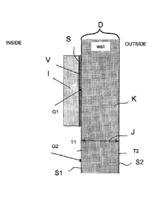
Figure 1 shows a measuring device according to the present invention, placed
against a
wall, the U-value of which is to be determined.
With reference to the figure's reference symbols, it can therefore be
concluded that the
present invention can be used to measure the heat flow J through a
construction K, having
a thickness of D.
The construction, which can consist of, instead of the vertical wall in the
figure, also a
horizontal or inclined surface, for instance a ceiling or a floor in a
building, or a separate,
for instance, single board or a wall, ceiling or floor element, comprises
¨ a first surface SI which is in contact with the air on the inside, and
¨ a second surface S2 which is in contact with the outside air.
There is a temperature difference between the first surface S1 and the second
surface S2
when the temperature of the outside air (on the cold side) and the temperature
of the inside
(the warm side) differ from each other. Thus, the temperature T1 at the first
surface Si
differs from the temperature T2 at the second surface S2; in the present case
Ti > T2.
Hence, a temperature difference arises across the construction.
CA 02870379 2014-10-14
WO 2013/153251 PCT/F12012/050357
6
It should be noted that in the present method, it is not necessary to measure
the temperature
T2, instead, the measurement process which is described below, is focused on
the surface
temperature T1 on the inside of the construction. However, when the U-value is
calculated,
data about the temperature of the warm side (not to be confused with the
surface
.. temperature of the inner wall) and of the outer air is also required. The
latter is determined
at a distance from the outer wall, preferably > 1 cm, and the distance should
not exceed 1
m.
Before the device is attached to the wall, the Ti' = T1" = the temperature of
the inner wall
surface.
As also appears in the schematic picture shown in figure 1, in one embodiment,
the
measuring device comprises a frame S, a heating element V, two temperature
sensors GI
and G2, insulation I and a battery and electronics (not shown). The
temperature sensor GI,
which is located under the insulation I, together with the heating element V,
will be
insulated from the air of the room, and becomes colder compared with the
temperature
sensor G2 (reference), which is located at the side of the instrument on the
wall. Ti is the
normal temperature of the wall surface.
According to a preferred embodiment, the frame S is comprised of a plate, the
shortest
dimension of which is at least 2 cm, in particular at least 3 cm, and which is
transverse to
the inside of the frame. The frame (S) is comprised of an essentially square
or circular
plate, which is at least mainly covered with an insulation layer. An
appropriate size of the
frame is approximately 10-1000 cm2, preferably approximately 20-500 cm2,
typically
approximately 30-250 cm2. According to one embodiment, the size of the plate,
which is
brought into contact with the construction to be examined, is approximately
100 cm2 20
%. In other words, it is a question of a relatively small construction, which
makes it
possible to measure smaller parts of the construction.
The first sensor G1 is arranged on the inside of the plate S and the second
sensor G2 is
attached to the plate by a bracket. Typically, the distance between the
sensors is
approximately 10-150 mm, preferably approximately 15-100 mm. The second sensor
may
be spring loaded, for it to be pressed against the surface at the same time
the frame is
pressed against it.
CA 02870379 2014-10-14
WO 2013/153251 PCT/F12012/050357
7
Preferably, the heat transfer surface V is comprised of thermal resistance
coils, which
cover a substantial part of the inside of the frame S.
According to a preferred embodiment, the instrument of the present invention
comprises a
temperature-controlled, insulated base plate with integrated heating coils,
which is placed
in direct physical contact with the wall surface. Between the plate and the
wall surface
there is essentially no layer of air. Unlike, for example, in the well-known
box-design
given in CN 2476020, in the present invention there is no need to consider the
heat
transfer resistance from the inside air to the wall surface, because the
sensor measures
the surface temperature of the surrounding wall and the base plate adjusts
the underlying wall surface to the temperature of the surrounding wall.
The measurement is carried out so that at least two temperature sensors GI and
G2 are first
attached against the first surface SI, and at least one of the temperature
sensors, G1 is
insulated thermally from a second temperature sensor G2, in such a way that
the
temperature T1', which is sensed by the thermally insulated sensor GI, is
affected by the
heat flow through the construction K more than the temperature Ti", which is
sensed by
the second temperature sensor G2
T" should ideally be totally independent of the heat flow through the
construction K. G2
shall therefore only measure the surface temperature of the inner wall, which
temperature
should in a stationary state be constant because the heat flow from the room
to the surface
of the inner wall is equal to the heat flow from the inner wall surface to the
outer wall
surface.
After the device is attached to the wall surface the measurement starts. The
temperature
difference T1"-T1' between the sensor G2, and the thermally insulated sensor
GI is
determined.
The temperature Ti' begins to decrease, if the temperature on the outer side
is lower
than on the inside, or rise, if the temperature on the outer side is higher
than on the inside
SUBSTITUTE SHEET (RULE 26)
CA 02870379 2014-10-14
WO 2013/153251 PCT/F12012/050357
8
while T1" is more or less unchanged. From this it follows that the absolute
value of the
temperature difference T1"-T1' changes (i.e. becomes different from 0).
Following this, the heating element is switched on to heat the wall against
which the
temperature sensor G1 is attached. The heating element supplies heat until the
same
temperature is reached as the reference temperature, i.e. the moment when the
temperature
difference is as close as possible to zero. When a stable state is reached, it
is assumed that
all power supplied is led out through the wall. Thus it is possible to
determine the U-
value of the wall by considering the input power, the surface area (m2) which
is covered
by the instrument, i.e. the insulation, and the temperature difference between
the hot
side (inside air) and the cold side (outside air).The plate is electronically
adjusted to the
temperature of the console sensor.
With reference to the above, the method according to a preferred embodiment
can be
summarized as follows:
The device which is placed for instance on a wall, insulates the wall from the
inside air.
Therefore, the temperature begins to fall in the part of the wall which is
covered by the
device. To keep the temperature of the covered wall surface at the same level
as the
temperature of the surrounding wall surface, the base plate is heated with
electrical
energy. At equilibrium, the electrical energy fed in per time unit is equal to
the heat
flow through the wall surface covered by the device. Based on this heat flow
and the
temperatures of the warm and the cold side, it is possible to determine the
heat leakage of
the wall.
In one embodiment, which should only be seen as an example and in no way
limitative of
the present invention, an algorithm is used which means that when the
difference between
the temperatures T1"-T1' exceeds a predetermined first difference value ATA,
the
thermally insulated sensor GI is supplied with energy E, in order to reduce
the temperature
difference so that it falls below a predetermined second difference value ATB.
Starting
from the power supplied, the heat flow J through the construction is
determined as a
function of the temperature difference AT.
SUBSTITUTE SHEET (RULE 26)
CA 02870379 2014-10-14
WO 2013/153251 PCT/F12012/050357
9
The temperature differences ATA and ATB can be chosen to be arbitrarily small
to allow a
supply of heat which is practically continuous. In one embodiment, ATA is
within a range
of approximately 0.1-10 degrees and ATB within a range of approximately 0.01-5
degrees.
The control may be a simple on-off control, HD control or some more advanced
control
algorithm. It is important that the two temperatures follow each other (follow-
up control)
as well as possible, because otherwise the measuring device will provide false
measured
values.
What is not shown in the picture is an LCD display that is integrated into the
instrument. The display shows the temperature and the U-value when the
device has reached thermal equilibrium. The electronic components are placed
on the
same circuit board as the heating coil, but on the other side.
According to a preferred embodiment, all the electronic components are surface
mounted
because it is not possible to drill holes through the board due to the heating
coil, The
advantages of such an assembly are that the instrument will be lighter, more
affordable, simpler and more flexible due to smaller (mostly thinner)
components.
Example
Tests have been performed on various materials with well-known thermal
conductivity to
analyze the performance and accuracy of the measuring instrument. The thermal
conductivity of each material is commonly referred to as its A value which is
a material
constant. To get the U-value for a particular piece of material, the A value
is divided by the
thickness x of the material
U= -
x
Numerous tests have been performed on an aquarium-like water tank. The
aquarium is
insulated on all sides except one side where the test material is attached.
The aquarium has
SUBSTITUTE SHEET (RULE 26)
CA 02870379 2014-10-14
WO 2013/153251 PCT/F12012/050357
two water connections: one inlet and one outlet. The tests have been conducted
with a
constant inlet and outlet so that the water moves and is replaced. It can be
assumed that the
temperature is fairly identical and constant throughout the aquarium,
including the surface
of the glass against the test material, which is the most important.
5
The water temperature is recorded at the end of each measurement by means of a
mercury
thermometer in the water. A small deviation (maximum 0.5 C) has still been
found in the
water and thus the tip of the thermometer has been held against the glass
behind the test
material and measuring instrument (the prototype).
The measuring instrument is monitored and achievement of thermal equilibrium
(steady
state) is determined. After that, the U-value is calculated from the
difference between the
steady state temperature and outside temperature, and the effect consumed at
the
temperature achieved at the steady state.
In order to evaluate the reliability of the measuring instrument, measurements
have been
carried out on materials having known U-values. Figures 2 and 3 show the
measured U-
value as a function of the known U-value (theoretical U-value). The pink line
that lies as
a diagonal in both graphs demonstrates the theoretical U-values for the
various
materials. The green triangles (Figure 2) and the blue points (Figure 3) in
the
graphs demonstrate the U-values measured with the measuring instruments.
Ideally, of course, the points would fall on the diagonal line, but already
the
results shown in Figures 2 and 3 show that the correlation is quite good.
Figure 4 shows a graph illustrating the power consumption of the instrument as
a function
of time, and the temperatures of the sensors as a function of time, during the
entire period
the instrument has been running. The red line in the graph shows the effect by
which the
instrument heats the heating coil. The green line is the temperature of the
sensor Gl,
which is below the heating coil. The blue line represents the sensor G2 that
measures
the real temperature of the wall.
SUBSTITUTE SHEET (RULE 26)
CA 02870379 2014-10-14
WO 2013/153251 PCT/F12012/050357
11
The figure clearly shows that the temperature sensor GI which is located below
the heating
coil begins to cool down after a period of time, due to the influence of the
heat flow
generated through the wall. When the difference between the two sensors G1 and
G2 is
large enough, the instrument turns on the power and begins to heat the loop.
After that, the
instrument adjusts the power, in order to achieve the steady-state mode. The
graph shows
that after approximately 110 minutes, the steady state is reached. After the
programme has
calculated the result and shown it on the display, the measurement is
terminated.
SUBSTITUTE SHEET (RULE 26)