Note: Descriptions are shown in the official language in which they were submitted.
CA 02870429 2014-10-14
DESCRIPTION
OPENING AND CLOSING DEVICE AND RESPIRATORY ASSISTANCE DEVICE
Technical Field
[0001]
The present invention relates to an opening and closing
device and a respiratory assistance device.
Background Art
[0002]
Respiratory assistance devices such as artificial
respirators are used in medical practice. A
typical
respiratory assistance device includes an oxygen supply source
such as an oxygen tank, an inspiratory pipe connected to the
supply source, a mask attached to a tip of the inspiratory
pipe, an expiratory pipe branched from the inspiratory pipe,
an expiratory valve fixed to a tip of the expiratory pipe, etc.
(for example, Japanese Patent Application Laid-Open Nos. Hei.
02-131765, Hei. 02-131773, Hei. 02-131774, and Hei. 05-245204).
[0003]
Various methods such as a controlled ventilation
(Controlled Ventilation) method used for a patient in the
absence of spontaneous breathing (a patient under general
anesthesia, during cardiopulmonary resuscitation, or in a
critical condition) and an assisted ventilation (Assisted
Ventilation) method in which a positive pressure (Positive
Pressure) is created in an air passage in synchronization with
1
CA 02870429 2014-10-14
the spontaneous breathing of a patient are employed for such
respiratory assistance devices.
[0004]
In a respiratory assistance device employing any of these
methods, oxygen sent out from the oxygen tank is supplied to
lungs as inspiratory air via the inspiratory pipe. The oxygen
supplied to the lungs is then exhaled by the lungs as
expiratory air. If the expiratory air is discharged into the
expiratory pipe, a pressure in the expiratory pipe is
increased. A control unit then receives a sensing signal from
a pressure sensor having detected the pressure increase in the
expiratory pipe and opens the expiratory valve. In this manner,
the expiratory air is emitted to the outside from the
expiratory pipe.
Summary of Invention
Technical Problem
[0005]
A diaphragm valve has been known as an expiratory valve
employed in such a respiratory assistance device. The
diaphragm valve includes: a valve seat formed along a
circumference of an opening of a hole through which the
expiratory air passes (hereinafter referred to as an
expiratory hole); and a valve element movable between a
position supported by the valve seat and blocking the
expiratory hole (blocking position) and a position away from
2
CA 02870429 2014-10-14
the valve seat and opening the expiratory hole (opening
position).
[0006]
The valve element of this diaphragm valve is required to
have rigidity just enough to resist a pressure from the
expiratory hole in order to maintain the blocking position. As
means for enhancing the rigidity of the valve element,
changing the forming material thereof, reviewing the shape
thereof, increasing the size of the valve element itself, and
the like, can be considered.
[0007]
However, if the forming material or shape of the valve
element is changed, the procurement cost or processing cost
thereof is thereby increased. Moreover, if the size of the
valve element itself is increased, the downsizing of the
diaphragm valve becomes difficult to achieve. These problems
are not limited to the expiratory valve employed in the
respiratory assistance device but common to the diaphragm
valve.
[0008]
The present invention has been made in view of the
aforementioned problems. It is an object of the present
invention to provide an opening and closing device having
rigidity enough to resist a pressure from the hole and capable
of being manufactured inexpensively and downsized easily, and
3
CA 02870429 2014-10-14
a respiratory assistance device including the opening and
closing device.
Solution to Problem
[0009]
As a result of intensive research made by the present
inventor, the aforementioned object is achieved by the
following means.
[0010]
An opening and closing device includes: a separating
member having a separating surface with a hole through which a
fluid passes being opened; and an opening and closing
mechanism having a deformable member deformable in a plane
direction of the separating surface, wherein the opening and
closing mechanism can be transitioned by deformation of the
deformable member between a first state and a second state in
which opening amounts of the hole are different from each
other.
[0011]
Preferably, the deformable member is formed in a shape of
a plate deformable in a thickness direction thereof, and the
deformable member erects from the separating surface so that a
direction of the deformation coincides with the plane
direction of the separating surface. Moreover, the hole is
preferably formed in a slit shape and the deformable member
preferably covers the hole with a side surface thereof.
4
CA 02870429 2014-10-14
[0012]
Preferably, the opening and closing mechanism includes a
cover provided at a free end side of the deformable member and
covers the hole by moving the cover.
Moreover, said hole
includes a first hole and a second hole and the first hole and
the second hole are preferably opened in the separating
surface, and the opening and closing mechanism preferably can
be transitioned by deforming the common deformable member
between a state in which the first hole is blocked and the
second hole is opened and a state in which the second hole is
blocked and the first hole is opened.
[0013]
Preferably, the deformable member is a piezoelectric
element, and the opening and closing device includes a
controller for controlling deformation of the piezoelectric
element. Moreover, a biasing mechanism for biasing the opening
and closing mechanism toward the separating surface is
preferably provided.
[0014]
A respiratory assistance device includes the above-
described opening and closing device, and the separating
member is formed by: a mask for covering a nose or a mouth;
and a communicating pipe communicated with a space formed
inside the mask in a worn state.
[0015]
5
CA 02870429 2014-10-14
The hole is preferably formed in the mask or the
communicating pipe. Moreover, the hole preferably forms an
expiratory pathway through which expiratory air exhaled from
the nose or the mouth passes.
[0016]
A respiratory assistance device includes: the above-
described opening and closing device; a flow passage through
which an expiratory or inspiratory gas passes; an inspiratory
nozzle disposed in the flow passage, for jetting an
acceleration gas in an inspiratory direction; an expiratory
nozzle disposed in the flow passage closer to an expiratory
direction side than the inspiratory nozzle, for jetting an
acceleration gas in the expiratory direction; a pump unit for
supplying the acceleration gas to the inspiratory nozzle and
the expiratory nozzle; an inspiratory Venturi wall extending
from the inspiratory nozzle toward the inspiratory direction
in the flow passage so as to spread out the acceleration gas
emitted from the inspiratory nozzle in order to set the
inspiratory direction side from the inspiratory nozzle at a
negative pressure; and an expiratory Venturi wall extending
from the expiratory nozzle toward the expiratory direction in
the flow passage so as to spread out the acceleration gas
emitted from the expiratory nozzle in order to set the
expiratory direction side from the expiratory nozzle at a
negative pressure, wherein the opening and closing device can
6
CA 02870429 2014-10-14
be transitioned between a state in which one of the
inspiratory nozzle and the expiratory nozzle is blocked and a
state in which the other one of them is blocked.
Advantageous Effects of Invention
[0017]
The above-described opening and closing device has
rigidity enough to resist a pressure from the hole and can be
manufactured inexpensively and downsized easily. Such an
opening and closing device is suitable for use also as an
opening and closing device (for example, an expiratory valve)
in a respiratory assistance device.
Brief Description of Drawings
[0018]
Fig. 1 is a schematic view illustrating a configuration
of a respiratory assistance device according to a first
embodiment of the present invention.
Fig. 2A is a schematic view of an expiratory valve
provided in a mask, illustrating a state in which the
expiratory valve opens an expiratory hole.
Fig. 2B is a schematic view of the expiratory valve
provided in the mask, illustrating the state in which the
expiratory valve opens the expiratory hole.
Fig. 2C is a schematic view of the expiratory valve
provided in the mask, illustrating a state in which the
expiratory valve blocks the expiratory hole.
7
CA 02870429 2014-10-14
Fig. 2D is a schematic view of the expiratory valve
provided in the mask, illustrating the state in which the
expiratory valve blocks the expiratory hole.
Fig. 3 is a block diagram illustrating a hardware
configuration of a control unit.
Fig. 4 is a block diagram illustrating a functional
configuration of the control unit.
Fig. 5 shows schematic views illustrating a control
example of the respiratory assistance device wherein (A) shows
a case when a user performs expiration and (B) shows a case
when the user performs inspiration.
Fig. 6 is a schematic view illustrating a configuration
of a respiratory assistance device according to a second
embodiment of the present invention.
Fig. 7 is a schematic view illustrating a configuration
of a respiratory assistance device according to a third
embodiment of the present invention.
Fig. 8 is a schematic view illustrating a configuration
of a respiratory assistance device according to a fourth
embodiment of the present invention.
Fig. 9 is a schematic view illustrating a configuration
of a respiratory assistance device according to a fifth
embodiment of the present invention.
Fig. 10(A) is a cross-sectional view illustrating a
configuration example of a micro pump and Fig. 10(B) is a
8
CA 02870429 2014-10-14
graph showing pressure-flow rate lines of the micro pump.
Fig. 11 is a schematic view illustrating a configuration
of a respiratory assistance device according to a sixth
embodiment of the present invention.
Fig. 12 is a schematic view illustrating an expiratory
valve capable of selectively blocking an expiratory hole and
an inspiratory hole provided in a mask.
Fig. 13 shows schematic views illustrating the expiratory
valve capable of selectively blocking the expiratory hole and
the inspiratory hole provided in the mask wherein (A) shows a
state in which the expiratory valve blocks only the expiratory
hole and (B) shows a state in which the expiratory valve
blocks only the inspiratory hole.
Fig. 14 is a schematic view of a mask having a plurality
of expiratory holes.
Fig. 15 shows schematic views of an expiratory valve
including a piezo element and a cover provided in the piezo
element and capable of opening and closing an expiratory hole
by deformation of the piezo element.
Fig. 16 shows schematic views illustrating a respiratory
assistance device including an expiration and inspiration
switching valve capable of selectively blocking an expiratory
nozzle and an inspiratory nozzle.
Fig. 17(A) is a schematic view of the respiratory
assistance device when air is emitted from the expiratory
9
CA 02870429 2014-10-14
nozzle and Fig. 17(B) is a schematic view of the respiratory
assistance device when air is emitted from the inspiratory
nozzle.
Fig. 18(A) is a cross-sectional view taken along the line
A-A, illustrating an outline of an expiratory valve provided
in a mask and components disposed therearound, and Fig. 18(B)
is a cross-sectional view taken along the line B-B,
illustrating an outline of the expiratory valve provided in
the mask and the components disposed therearound.
Fig. 19 is an exploded perspective view illustrating an
outline of the expiratory valve provided in the mask and the
respective components disposed around the expiratory valve.
Description of Embodiments
[0019]
Embodiments of the present invention will now be
described below with reference to the accompanying drawings.
[0020]
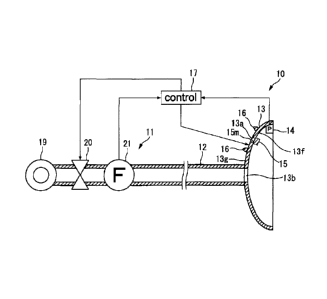
Fig. 1 illustrates, as an example, a configuration of a
respiratory assistance device 10 for medical use according to
the first embodiment of the present invention. The respiratory
assistance device 10 includes: a supply source 11 for sending
out an inspiratory gas; an inspiratory pipe 12 with its base
end being connected to the supply source 11; a mask 13
attached to a tip of the inspiratory pipe 12 and having an
expiratory hole 13a; an air gauge 14 for measuring a gas
CA 02870429 2014-10-14
pressure inside the mask 13; an expiratory valve 15 provided
in the mask 13 and serving as an opening and closing mechanism
for the expiratory hole 13a; a plurality of safety members 16
provided around the expiratory hole 13a so as to protrude
toward the outer side of an expiratory pathway; and a control
unit 17 for performing overall control on the entire device.
The mask 13 and the expiratory valve 15 together form an
opening and closing device.
[0021]
The mask 13 is a wearing device that covers a mouth and a
nose. The mask 13 serves to separate the mouth and the nose
from the ambient air (separating member).
The mask 13 is
provided with an inspiratory hole 13b. The inspiratory pipe 12
and the mask 13 are communicated with each other via the
inspiratory hole 13b. An inspiratory pathway is formed by the
inspiratory pipe 12, the inspiratory hole 13b, and the mask 13.
The expiratory pathway is formed by the mask 13 and the
expiratory hole 13a. Note that the mask 13 may be a wearing
device that covers either the mouth or the nose.
[0022]
The supply source 11 includes: a gas tank 19 that retains
a gas such as air or oxygen in a compressed state; a
regulating valve 20 for regulating a flow rate of the gas sent
out from the gas tank 19; and a flowmeter 21 for measuring the
flow rate of the gas regulated by the regulating valve 20. The
11
CA 02870429 2014-10-14
regulating valve 20 is controlled on the basis of sensing data
(measured results, sensing signals) from the air gauge 14 and
from the flowmeter 21. While the regulating valve 20 is not
limited to a particular type, an electric valve, an
electromagnetic valve with a high response speed, or the like,
can be employed. The flowmeter 21 outputs the sensing data to
the control unit 17.
[0023]
The inspiratory pipe 12 is formed by a bellows tube made
of a resin. The inspiratory pipe 12 and the mask 13 worn by a
patient together form a space and serve as a pathway for the
gas sent out from the supply source 11. A gas pressure inside
the inspiratory pipe 12 coincides with a gas pressure inside
the mask 13 worn by the patient in a steady state. The air
gauge 14 outputs the sensing data to the control unit 17.
[0024]
As shown in Figs. 2A to 2D, the expiratory valve 15 emits
the gas inside the mask 13 to the outside of the mask 13 by
opening and closing the expiratory hole 13a formed in a slit
shape and functions as a check valve for preventing a back-
flow thereof. The plate-shaped expiratory valve 15 is a valve
having a monomorph (unimorph) structure in which a piezo
element (piezoelectric element) 15a to be displaced according
to an amount of voltage applied is layered on a metal plate
15b and having a cantilever structure. The respiratory
12
CA 02870429 2014-10-14
assistance device 10 further includes a fixing member 22 for
fixing one end of the expiratory valve 15 to the mask 13. The
fixing member 22 is provided so as to erect from an inner
surface 13f of the mask 13. The one end of the expiratory
valve 15 is fixed to the mask 13 by the fixing member 22 with
a position erecting from the inner surface 13f. Note that the
fixing member 22 is preferably provided with a fixing groove
into which the one end of the expiratory valve 15 can be
fitted. A cantilever length of the expiratory valve 15 is
preferably about 30 mm or more and about 40 mm or less. A
displacement stroke of the expiratory valve 15 is preferably 2
mm or more and 3 mm or less. Note that the piezo element may
have a both-end supported structure.
[0025]
The piezo element 15a is deformable between an extended
state (see Figs. 2A and 2B) and a bent state (see Figs. 20 and
2D) by turning ON and OFF the voltage application thereto.
When the piezo element 15a is in the extended state, a side
surface 15m of the expiratory valve 15 is in a state in which
the expiratory hole 13a is opened. When the piezo element 15a
is in the bent state, on the other hand, the side surface 15m
of the expiratory valve 15 is in a state in which the
expiratory hole 13a is blocked. In this manner, the expiratory
valve 15 becomes deformable as a result of the deformation of
the piezo element 15a. Moreover, the expiratory valve 15 is
13
CA 02870429 2014-10-14
provided on the inner surface 13f so that a deformation
direction thereof, i.e., a thickness direction thereof,
coincides with the plane direction of the inner surface 13f of
the mask 13. Moreover, it is preferable that the expiratory
valve 15 be provided on the inner surface 13f so that the side
surface 15m slides along the inner surface 13f by the
deformation of the expiratory valve 15. The inner surface 13f
may be a flat surface or a curved surface. Thus, the
expiratory valve 15 can be transitioned by the deformation of
the piezo element 15a between the state in which the
expiratory hole 13a formed in the mask 13 is opened (see Figs.
2A and 2B) and the state in which by the side surface 15m of
the expiratory valve 15, the expiratory hole 13a is blocked by
the side surface 15m (see Figs. 2C and 2D).
[0026]
The piezo element 15a may be in the bent state when a
voltage is being applied thereto and in the extended state
when no voltage is being applied thereto as shown in Figs. 2A
to 2D. Or alternatively, the piezo element 15a may be in the
extended state when a voltage is being applied thereto and in
the bent state when no voltage is being applied thereto.
[0027]
Although the expiratory valve 15 with the monomorph
structure is introduced here, it is apparent that a bimorph
structure in which two piezo elements are attached together
14
CA 02870429 2014-10-14
can be employed instead.
[0028]
Referring back to Fig. 1, if the expiratory hole 13a is
covered by an object outside the mask 13, the expiratory
pathway cannot be secured by the actuation of the expiratory
valve 15. It is therefore preferable that the safety members
16 be provided in the mask 13.
The safety members 16 are
formed so as to protrude from an outer surface 13g of the mask
13 and arranged so as to be dotted near the expiratory hole
13a. Consequently, a gap can be formed between an aperture
plane of the expiratory hole 13a on the outer surface 13g side
and the object covering the expiratory hole 13a. Thus, the
expiratory pathway can be secured by the actuation of the
expiratory valve 15.
[0029]
As shown in Fig. 3, the control unit 17 includes a CPU 24,
a first storage medium 25, a second storage medium 26, a third
storage medium 27, an input device 28, a display device 29, an
input and output interface 30, and a bus 31.
[0030]
The CPU 24 is what is called a central processing unit
and executes various programs to realize various functions of
the control unit 17. The first storage medium 25 is what is
called a RAM (Random Access Memory) and used as a work area
for the CPU 24. The second storage medium 26 is what is called
CA 02870429 2014-10-14
a ROM (Read Only Memory) and stores a basic operating system
executed by the CPU 24. The third storage medium 27 is
configured by a hard disk device incorporating a magnetic disk,
a disk device accommodating a CD, a DVD, or a BD, a non-
volatile semiconductor flash memory device, and the like. The
third storage medium 27 saves various programs executed by the
CPU 24.
[0031]
The input device 28 is an input key, a keyboard, or a
mouse and inputs a variety of information. The display device
29 is a display and displays various operating states. A power
supply for operating the expiratory valve 15 and control
signals are inputted to and outputted from the input and
output interface 30. Furthermore, the input and output
interface 30 also obtains data such as a program from an
external personal computer. The bus 31 serves as a line for
integrally connecting the CPU 24, the first storage medium 25,
the second storage medium 26, the third storage medium 27, the
input device 28, the display device 29, the input and output
interface 30, and the like to achieve communication among them.
[0032]
Fig. 4 shows a functional configuration obtained when a
control program stored in the control unit 17 is executed by
the CPU 24. The control unit 17 includes: a sensing part 34;
an expiratory valve control part 35; and a regulating valve
16
CA 02870429 2014-10-14
control part 36, as the functional configuration. The sensing
part 34 constantly obtains the sensing data from the air gauge
14 and transmits such data to the expiratory valve control
part 35. Furthermore, the sensing part 34 constantly obtains
the sensing data from the air gauge 14 and the flowmeter 21
and transmits such data to the regulating valve control part
36. The expiratory valve control part 35 refers to the sensing
data from the sensing part 34 and controls a control signal to
the expiratory valve 15 so as to approximate a target opening
amount. The regulating valve control part 36 refers to the
sensing data from the sensing part 34 and controls a control
signal to the regulating valve 20 so as to approximate a
target flow rate value.
[0033]
Control examples for the respiratory assistance device 10
will be described next with reference to Fig. 5(A) and Fig.
5(B).
[0034]
First of all, if expiratory air is exhaled from a mouth
or nose wearing the mask 13, the pressure inside the mask 13
is increased. If the pressure inside the mask 13 is increased,
the increased value is sensed by the air gauge 14. The sensing
data is outputted to the control unit 17. The control unit 17
controls the expiratory valve 15 on the basis of the sensing
data. More specifically, the control unit 17 operates the
17
CA 02870429 2014-10-14
expiratory valve 15 so as to open the expiratory hole 13a as
shown in Fig. 5(A). The expiratory air is emitted to the
outside of the mask 13 through the expiratory hole 13a.
[0035]
Emitting the expiratory air to the outside of the mask 13
causes the pressure inside the mask 13 to decrease. If the
pressure inside the mask 13 is decreased, the decreased value
is sensed by the air gauge 14. The sensing data is outputted
to the control unit 17. The control unit 17 controls the
expiratory valve 15 on the basis of the sensing data. More
specifically, the control unit 17 operates the expiratory
valve 15 so as to block the expiratory hole 13a. Consequently,
a closed space is formed inside the mask 13, thereby allowing
for an inspiratory operation.
[0036]
Subsequently, when inspiration is performed by the mouth
or nose wearing the mask 13, the pressure inside the mask 13
is decreased. If the pressure inside the mask 13 is decreased,
the decreased value is sensed by the air gauge 14. The sensing
data is outputted to the control unit 17. The control unit 17
controls the supply source 11 on the basis of the sensing data.
More specifically, the control unit 17 opens the regulating
valve 20 so as to send out the gas from the gas tank 19 as the
inspiratory air as shown in Fig. 5(B). Thereafter, the
pressure inside the mask 13 is increased. If the pressure
18
CA 02870429 2014-10-14
inside the mask 13 is increased, the increased value is sensed
by the air gauge 14. The sensing data is outputted to the
control unit 17. The control unit 17 controls the supply
source 11 on the basis of the sensing data. More specifically,
the control unit 17 closes the regulating valve 20 so as to
stop the sending out of the gas from the gas tank 19 as the
inspiratory air. Thereafter, the expiratory operation and the
inspiratory operation are repeated in the same manner.
[0037]
Here, if the deformation direction of the piezo element
15a coincides with a direction away from the inner surface 13f
or closer to the inner surface 13f, the deformation direction
of the piezo element 15a is substantially parallel to the
direction of a force generated by a pressure difference
between the inside and outside of the mask 13. Thus, the piezo
element 15a is easily deformed by the force generated by the
pressure difference between the inside and outside of the mask
13. In the above-described respiratory assistance device 10,
on the other hand, the expiratory valve 15 is disposed so that
the deformation direction of the piezo element 15a coincides
with a direction along the inner surface 13f. Therefore, the
deformation direction of the piezo element 15a is
substantially perpendicular to the direction of the force
generated by the pressure difference between the inside and
outside of the mask 13. Consequently, the piezo element 15a is
19
CA 02870429 2014-10-14
hardly deformed by the force generated by the pressure
difference between the inside and outside of the mask 13. In
this manner, the expiratory valve 15 has rigidity enough to
resist the pressure from the expiratory hole 13a. Moreover,
since the piezo element can be used as the expiratory valve 15
itself, an increase in procurement cost or processing cost can
be avoided.
[0038]
As described above, the opening and closing device formed
by the mask 13 and the expiratory valve 15 has rigidity enough
to resist the pressure from the hole and can be manufactured
inexpensively and downsized easily. Furthermore, due to its
simple configuration, the opening and closing device can
easily obtain high reliability.
[0039]
Moreover, the expiratory valve 15 is disposed so that the
deformation direction of the piezo element 15a coincides with
the direction along the inner surface 13f. Therefore, as
compared with the case where the deformation direction of the
piezo element 15a coincides with the direction away from the
inner surface 13f or closer to the inner surface 13f, a fully-
opened state of the expiratory hole 13a can be easily obtained
with a smaller deformation amount of the piezo element 15a.
[0040]
Moreover, since the piezo element 15a, capable of easily
CA 02870429 2014-10-14
adjusting the deformation amount thereof by an applied voltage
value, is used, the opening percentage of the expiratory hole
13a can be easily adjusted. Consequently, the discharge amount
of the expiratory air can be adjusted. Therefore, the flow
rate of the expiratory air emitted from the expiratory valve
can be prevented from changing abruptly. In other words,
the gas pressure inside the mask 13 can be prevented from
changing abruptly, thereby easing a load on the patient.
[0041]
10 Furthermore, the expiratory valve 15 is configured to
include the piezo element 15a. Thus, as compared with a case
where an electromagnetic valve is employed as the expiratory
valve, the expiratory valve 15 has a longer lifetime and is
more durable.
15 [0042]
Thus, the application of the present invention allows for
use as a home artificial respirator by a patient suffering
from sleep apnea syndrome or the like. [0043]
Moreover, the expiratory valve 15 is in the state in
which the expiratory hole 13a is opened when no voltage is
being applied to the piezo element 15a. Therefore, even when
the expiratory valve 15 stops its operation due to a failure
or the like, the expiratory valve 15 is forced to be in the
state in which the expiratory hole 13a is opened. Thus, the
expiratory pathway can be secured.
21
CA 02870429 2014-10-14
[0044]
Also, since the expiratory valve 15 is provided in the
mask 13, the responsiveness of the expiratory valve 15 to the
expiratory operation is high. Thus, a load on the patient is
small.
[0045]
Furthermore, since the expiratory valve 15 is provided
inside the mask 13, the expiratory valve 15 can be prevented
from interfering with an object outside the mask 13. Note that
the expiratory valve 15 may be provided on the outer surface
of the mask 13.
[0046]
Fig. 6 illustrates, as an example, a configuration of a
respiratory assistance device 40 according to the second
embodiment. The first embodiment and the second embodiment
have many identical or similar portions. The description of
such portions will be therefore omitted when appropriate and
points different from those in the first embodiment will be
described mainly. Also with regard to the third and following
embodiments to be described later, descriptions common to the
other embodiments will be omitted when appropriate and points
different from those in the other embodiments will be
described mainly.
[0047]
In the respiratory assistance device 40, a vent hole 12a
22
CA 02870429 2014-10-14
is formed in the inspiratory pipe 12 instead of forming the
expiratory hole 13a (see Fig. 1) in the mask 13. Also, instead
of providing the expiratory valve 15 and the plurality of
safety members 16 in the mask 13, an expiratory valve 41 and a
plurality of safety members 42 are provided in the inspiratory
pipe 12 according to the respiratory assistance device 40.
Thus, the inspiratory pipe 12 functions also as the expiratory
pathway.
[0048]
The expiratory valve 41, having a configuration similar
to the expiratory valve 15 shown in Figs. 2A to 2D, is
provided on an inner surface 12f such that a deformation
direction thereof, i.e., a thickness direction thereof,
extends along the inner surface 12f of the inspiratory pipe 12
and a side surface thereof slides along the inner surface 12f
by the deformation thereof. Thus, the expiratory valve 15 can
be transitioned by the deformation of the piezo element
between a state in which the vent hole 12a is opened and a
state in which the vent hole 12a is closed. Moreover, the
safety members 42 are formed so as to protrude from an outer
surface 12g of the inspiratory pipe 12 and arranged so as to
be dotted near the vent hole 12a.
[0049]
It is preferable that the expiratory valve 41 be provided
at a position as close as possible to the mask 13 within a
23
CA 02870429 2014-10-14
range not causing a slow responsiveness to the expiratory
operation. Specifically, the expiratory valve 41 is provided
preferably at a position where a length from the mask 13 in
the inspiratory pipe 12 is within 300 mm, and more preferably
at a position within 100 mm. In other words, the expiratory
valve 41 is provided preferably at a position where a distance
of the expiratory pathway from an entrance into a body such as
a mouth is within 310 mm, and more preferably at a position
within 110 mm.
[0050]
Fig. 7 illustrates, as an example, a configuration of a
respiratory assistance device 50 according to the third
embodiment. In the respiratory assistance device 50, an
expiratory valve 51 and a plurality of safety members 52 are
provided in the mask 13 via an exhaust pipe 53 instead of
providing the expiratory valve 15 and the plurality of safety
members 16 directly on the mask 13. More specifically, the
exhaust pipe 53 is provided on the mask 13 so that a base end
thereof covers the expiratory hole 13a. A tip of the exhaust
pipe 53 is closed by a cap 54. A vent hole 53a is formed in a
middle portion of the exhaust pipe 53. Thus, the exhaust pipe
53 functions also as the expiratory pathway.
[0051]
The expiratory valve 51, having a configuration similar
to the expiratory valve 15 shown in Figs. 2A to 2D, is
24
CA 02870429 2014-10-14
provided on an inner surface 53f such that a deformation
direction thereof, i.e., a thickness direction thereof,
extends along the inner surface 53f of the exhaust pipe 53 and
a side surface thereof slides along the inner surface 53f by
the deformation thereof. Thus, the expiratory valve 51 can be
transitioned by the deformation of the piezo element between a
state in which the vent hole 53a is opened and a state in
which the vent hole 53a is blocked. Moreover, the safety
members 52 are formed so as to protrude from an outer surface
53g of the exhaust pipe 53 and arranged so as to be dotted
near the vent hole 53a. It is preferable that the exhaust pipe
53 be set as short as possible within a range not causing a
slow responsiveness of the expiratory valve 51 to the
expiratory operation. Specifically, a length of the exhaust
pipe 53 is preferably within 500 mm, and more preferably
within 300 mm.
[0052]
Fig. 8 illustrates, as an example, a configuration of a
respiratory assistance device 60 according to the fourth
embodiment. In the respiratory assistance device 60, an
expiratory valve 61 and a plurality of safety members 62 are
provided in the inspiratory pipe 12 via an exhaust pipe 63
instead of providing the expiratory valve 15 and the plurality
of safety members 16 directly on the mask 13. More
specifically, the exhaust pipe 63 is provided on the
CA 02870429 2014-10-14
inspiratory pipe 12 so that a base end thereof covers the vent
hole 12a. A tip of the exhaust pipe 63 is closed by a cap 64.
Also, a vent hole 63a is formed in a middle portion of the
exhaust pipe 63. Thus, the inspiratory pipe 12 functions also
as the expiratory pathway.
[0053]
The expiratory valve 61, having a configuration similar
to the expiratory valve 15 shown in Figs. 2A to 2D, is
provided on an inner surface 63f so that a deformation
direction thereof, i.e., a thickness direction thereof,
extends along the inner surface 63f of the exhaust pipe 63 and
a side surface thereof slides along the inner surface 63f by
the deformation thereof. Thus, the expiratory valve 61 can be
transitioned by the deformation of the piezo element between a
state in which the vent hole 63a is opened and a state in
which the vent hole 63a is blocked. Moreover, the safety
members 62 are formed so as to protrude from an outer surface
63g of the exhaust pipe 63 and arranged so as to be dotted
near the vent hole 63a.
[0054]
It is preferable that the exhaust pipe 63 be set as short
as possible within a range not causing a slow responsiveness
of the expiratory valve 61 to the expiratory operation.
Specifically, a length of the exhaust pipe 63 is preferably
within 500 mm, and more preferably within 300 mm. Moreover, it
26
CA 02870429 2014-10-14
is preferable that the exhaust pipe 63 be provided at a
position as close as possible to the mask 13. Specifically,
the exhaust pipe 63 is provided preferably at a position where
a length from the mask 13 in the inspiratory pipe 12 is within
150 mm, and more preferably at a position within 50 mm. In
other words, the exhaust pipe 63 is provided preferably at a
position where a distance of the expiratory pathway from an
entrance into a body such as a mouth is within 160 mm, and
more preferably at a position within 60 mm.
[0055]
Fig. 9 illustrates, as an example, a configuration of a
respiratory assistance device 70 according to the fifth
embodiment. The respiratory assistance device 70 includes a
micro pump 100 as the supply source 11 and includes only the
mask 13 as the inspiratory pathway. In other words, the micro
pump 100 is directly connected to the mask 13. This micro pump
100 is the micro pump proposed in Patent Literature WO
2008/069266. As shown in Fig. 10(A), the micro pump 100
includes: a primary blower chamber 101; and a secondary blower
chamber 102 formed outside the primary blower chamber 101.
[0056]
The primary blower chamber 101 includes: a piezoelectric
element 103 serving as an oscillation source; a diaphragm 104
to which the piezoelectric element 103 is fixed; and an
oscillation frame 105 to form a space together with the
27
CA 02870429 2014-10-14
diaphragm 104. The oscillation frame 105 has an opening 106
through which a fluid is moved between the inside and outside
of the primary blower chamber 101. The secondary blower
chamber 102 includes: a suction port 107 on the diaphragm 104
side; and a discharge port 108 provided so as to face the
opening 106.
[0057]
According to the thus described micro pump 100, when the
diaphragm 104 resonates by the piezoelectric element 103, the
fluid is moved between the primary blower chamber 101 and the
secondary blower chamber 102. A fluid resistance due to such a
fluid movement causes the oscillation frame 105 to resonate.
The resonance of the diaphragm 104 and the oscillation frame
105 causes the fluid to be sucked in from the suction port 107
and to be discharged from the discharge port 108.
[0058]
The micro pump 100 is suitable for use as a blower for
transporting a gas. The micro pump 100 can perform such
transportation without employing a check valve. While the
micro pump 100 is extremely small, having a box shape with an
outer diameter of about 20 mm x 20 mm x 2 mm, the micro pump
100 can transport air of about 1 L/min at maximum (when the
static pressure is 0 Pa) and can obtain a static pressure of
about 2 kPa at maximum (flow rate of 0 L/min) when the input
sine wave is set at 26 kHz under 15 Vpp (Volt peak to peak).
28
CA 02870429 2014-10-14
[0059]
On the other hand, the micro pump 100 transports a fluid
by means of the oscillation of the diaphragm 104 caused by the
piezoelectric element 103. Thus, there is naturally a limit in
its transportable fluid volume. This static pressure-flow rate
characteristic also exhibits a straight line as shown in Fig.
10(B). More specifically, in order to obtain a static pressure
of about 1 kPa, for example, the flow rate is 0.5 L/min.
[0060]
If the Vpp of the input sine wave is changed to 10 or 20,
the amplitude of the piezoelectric element 103 is thereby
changed. Thus, the flow rate and the pressure can be changed.
More specifically, if the Vpp of the input sine wave is
smoothly changed, the flow rate and the pressure can be
smoothly changed. Alternatively, if the frequency of the input
sine wave is changed, the flow rate and the pressure can be
changed. More specifically, if the frequency of the input sine
wave is smoothly changed, the flow rate and the pressure can
be smoothly changed. Note however that the flow rate and the
pressure each have an upper limit depending on the capacity of
the piezoelectric element 103 and the strength or durability
of components. The micro pump 100 is generally used at a rated
Vpp and a rated frequency.
[0061]
Although the monomorph (unimorph) structure in which the
29
CA 02870429 2014-10-14
single piezoelectric element 103 is attached to the diaphragm
104 is introduced here, it is apparent that the bimorph
structure in which two piezoelectric elements are attached
together in order to increase the amount of oscillation can be
employed instead.
[0062]
Fig. 11 illustrates, as an example, a configuration of a
respiratory assistance device 80 according to the sixth
embodiment. The respiratory assistance device 80 includes the
micro pump 100 as the supply source 11 and includes only the
inspiratory pipe 12 as the inspiratory pathway. In the
respiratory assistance device 80, an expiratory valve 81 and a
plurality of safety members 82 are provided in the inspiratory
pipe 12 instead of providing the expiratory valve 15 and the
plurality of safety members 16 in the mask 13. Thus,
the
inspiratory pipe 12 functions also as the expiratory pathway.
It is preferable that the expiratory valve 81 be provided at a
position as close as possible to the tip of the inspiratory
pipe 12 within a range not causing a slow responsiveness to
the expiratory operation and within a range not resulting in
an insertion thereof into the mouth of a patient. Furthermore,
in the respiratory assistance device 80, an air gauge 83 is
provided inside the inspiratory pipe 12 instead of providing
the air gauge 14 inside the mask 13.
[0063]
CA 02870429 2016-07-11
=
It is apparent that the respiratory assistance device
according to the present invention is not limited to the
specific embodiments described above and various modifications
can be made thereto without departing from the scope of the
present invention. Also, the constituent elements of the
above-described embodiments may be applied to other
embodiments to the extent possible.
[0064]
In other words, in the above-described embodiments, the
positions, sizes, shapes, and quantities in the respective
configurations can be changed appropriately. Modifications of
the first embodiment will be described below as examples.
[0065]
Modifications of the first embodiment will be described
specifically as examples. As shown in Figs. 12 to 13, it is
preferable that the expiratory hole 13a and the inspiratory
hole 13b formed in the mask 13 be provided so as to be close
to each other. "Being close" herein refers to a range smaller
than the deformation amount of the piezo element 15a. Thus,
the expiratory valve 15 can be transitioned by the deformation
of the piezo element 15a between a state in which only the
expiratory hole 13a formed in the mask 13 is blocked (see Fig.
13(A)) and a state in which only the inspiratory hole 13b is
blocked (see Fig. 13(B)). This reliably allows for switching
between a state in which the expiratory air inside the mask 13
31
CA 02870429 2014-10-14
is emitted to the outside of the mask 13 and a state in which
the inspiratory gas from the inspiratory pipe 12 is sent into
the mask 13. Furthermore, since the inspiratory pipe 12 is
formed in a protruding manner near the expiratory hole 13a on
the outer surface of the mask 13, the inspiratory pipe 12
functions also as a safety member.
[0066]
Alternatively, as shown in Fig. 14, a plurality of
expiratory holes 13a may be provided in the mask 13. These
expiratory holes 13a are provided at portions of the mask 13
facing the aperture plane of the tip portion of the
inspiratory pipe 12. Alternatively, any reference position XP
may be set at a portion of the mask 13 facing the aperture
plane of the tip portion of the inspiratory pipe 12 and the
expiratory holes 13a may be arranged around the reference
position XP. It is preferable that the expiratory valve 15 be
provided for each of the expiratory holes 13a formed in the
mask 13 to open and close the corresponding expiratory hole
13a. The plurality of expiratory valves 15 are controlled
independent of one another to open and close the expiratory
holes 13a, respectively. Thus, by changing the number of the
expiratory valves 15 to be opened, the flow rate of the
expiratory air can be adjusted. In this manner, without
controlling the applied amount of a voltage to the piezo
element 15a, the flow rate of the expiratory air can be
32
CA 02870429 2014-10-14
adjusted stepwisely only by controlling ON and OFF of the
voltage to the piezo elements 15a in order to change the
number of the expiratory valves 15 to be opened. In
other
words, the flow rate of the expiratory air can be adjusted
with such simple control. Moreover, the flow rate of the
expiratory air can be adjusted more smoothly by controlling
the applied amount of the voltage to the piezo element 15a.
[0067]
In the above-described embodiment, the expiratory valve
15 having the piezo element 15a, which is a deformable member,
is used as the opening and closing mechanism. Also, the
expiratory valve 15 is configured so as to be transitioned by
the deformation of the piezo element 15a between the state in
which the expiratory hole 13a is blocked by the side surface
15m (see Fig. 1) of the expiratory valve 15 (see Figs. 2C and
2D) and the state in which the expiratory hole 13a is opened
(see Figs. 2A and 2B). However, the present invention is not
limited thereto. The expiratory hole 13a may be opened and
closed by using a cover 85 provided at a free end side of the
expiratory valve 15. In this case, the expiratory valve 15 and
the cover 85 together form the opening and closing mechanism
(see Fig. 15). The cover 85 has a sliding surface to slide
along the inner surface 13f. The cover 85 is disposed so that
the deformation direction of the expiratory valve 15, i.e.,
the thickness direction of the expiratory valve 15, extends
33
CA 02870429 2014-10-14
along the inner surface 13f of the mask 13 and the sliding
surface slides along the inner surface 13f by the deformation
of the expiratory valve 15.
[0068]
Alternatively, in the above-described first to fourth
embodiments, the micro pump 100 may be provided as the supply
source 11 in place of the gas tank 19 or the like. In each of
the above-described embodiments including the cases of the
above-described fifth and sixth embodiments, a plurality of
micro pumps 100 may be provided and disposed in series or in
parallel or disposed in a matrix.
[0069]
Alternatively, while the mask 13 covering a mouth and a
nose is provided as the inspiratory pathway and the expiratory
pathway in the above-described first to fifth embodiments, a
wearing device such as a nosepiece worn by a nose may be
provided in place of the mask 13.
[0070]
Note that the shape of the expiratory hole 13a or the
inspiratory hole 13b (see Fig. 14) such as a circle (see Fig.
15), an ellipse, a polygon, or a slit shape (see Figs. 2A to
2D) may be appropriately determined depending on its usage.
[0071]
When the hole is opened and closed by means of a
temperature change, a bimetal may be used as the opening and
34
CA 02870429 2014-10-14
closing mechanism. In this case, it is advantageous in that
there is no need for a control unit controller. Coefficients
of thermal expansion, shapes, and sizes of the materials of
the bimetal may be determined so as to achieve transition
between the opened state and the closed state.
[0072]
In the above-described embodiments, the expiratory valve
is deformed between the fully-opened state of the
expiratory hole 13a (see Figs. 2A and 2B) and the fully-closed
10 state of the expiratory hole 13a (see Figs. 2C and 2D).
Depending on its usage, however, the expiratory valve 15 may
be deformed between a state in which the opening amount of the
expiratory hole 13a is A and a state in which the opening
amount of the expiratory hole 13a is B which is greater than A.
15 This allows the flow rate of the expiratory air to be adjusted
stepwisely.
[0073]
Moreover, the above-described opening and closing device
can be applied not only to the opening and closing of a hole
through which the expiratory air passes but also to the
opening and closing of a hole through which a fluid (a gas or
a liquid) passes and the opening and closing of a hole through
which a solid passes.
[0074]
Furthermore, another embodiment will be described. A
CA 02870429 2014-10-14
respiratory assistance device 10 shown in Fig. 16 is
configured to include: a flow passage 702 through which a gas
for respiration passes; an expiratory nozzle 704 and an
inspiratory nozzle 706 disposed in the flow passage 702 and
capable of emitting acceleration air in an expiratory
direction and in an inspiratory direction, respectively; a
pump unit 708 disposed on an outer surface of the flow passage
702 in a circumferential direction thereof; and a battery 710
for driving the pump unit 708. Venturi walls 720 are disposed
near the expiratory and inspiratory nozzles 704 and 706
disposed in the flow passage 702. The Venturi wall 720
includes a portion extending from the inspiratory nozzle 706
toward the inspiratory direction and a portion extending from
the expiratory nozzle 704 toward the expiratory direction.
Note that the battery 710 may be disposed at a remote location
or may be omitted by connecting a power supply line.
[0075]
In the pump unit 708, a plurality of (for example, four)
micro pumps 100 are arranged. The pump unit 708 is provided
with an integrated discharge port (not shown) which is a place
from which air transported by all the micro pumps 100 is
discharged finally. An expiration and inspiration switching
valve 725 is disposed at the integrated discharge port. The
expiration and inspiration switching valve 725 has a
configuration similar to that of the above-described
36
CA 02870429 2014-10-14
expiratory valve 15. The expiration and inspiration switching
valve 725 is switchable between a state in which the
inspiratory nozzle 706 is blocked and a state in which the
expiratory nozzle 704 is blocked. If the expiration and
inspiration switching valve 725 blocks the inspiratory nozzle
706, the air sent out from the pump unit 708 is emitted from
the expiratory nozzle 704 as shown in Fig. 17(A). The air
emitted from the expiratory nozzle 704 is spread out by the
Venturi walls 720, thereby setting the expiratory side in a
negative pressure state. Thus, carbon dioxide discharged from
the inspiratory side (lung side) is attracted and caused to
flow in the expiratory direction. Consequently, the expiratory
operation can be assisted. When the expiration and inspiration
switching valve 725 blocks the expiratory nozzle 704, on the
other hand, the air sent out from the pump unit 708 is emitted
from the inspiratory nozzle 706 as shown in Fig. 17(B). The
air emitted from the inspiratory nozzle 706 is spread out by
the Venturi walls 720, thereby setting the inspiratory side in
a negative pressure state. Thus, oxygen supplied from the
expiratory side is sucked in and is caused to flow in the
inspiratory direction (lung side). Consequently, the
inspiratory operation can be assisted.
[0076]
Furthermore, as a result of the reduced distance between
the pump unit 708 and the expiratory and inspiratory nozzles
37
CA 02870429 2014-10-14
704 and 706, an improved responsiveness in the breathing
assisting operation can be obtained.
[0077]
In the above-described embodiment, as shown in Figs. 2A
to 2D, an expiratory valve having the monomorph (unimorph)
structure formed by the piezo element (piezoelectric element)
15a and the metal plate 15b is employed as the expiratory
valve 15 and the piezo element 15a is switched between the
extended state (see Figs. 2A and 2B) and the bent state (see
Figs. 2C and 2D) by turning ON and OFF the voltage application
to the piezo element 15a. However, the behavior of the piezo
element 15 in the ON and OFF control of the voltage
application includes not only deformation in the thickness
direction thereof but also deformation in the width direction
thereof (the height direction from the inner surface 13f).
Therefore, if the turning ON and OFF of the voltage
application to the piezo element 15a is repeatedly performed,
a gap is created between the expiratory valve 15 and the inner
surface 13f as a result of the deformation in the width
direction of the piezo element 15a. Consequently, the
expiratory valve 15 can no longer close the expiratory hole
13a.
[0078]
If such is the case, it is preferable that a holding
groove 22m capable of holding one end of the expiratory valve
38
CA 02870429 2014-10-14
15 be formed in the fixing member 22 and a spring 22s for
biasing the expiratory valve 15 toward the inner surface 13f
be disposed in the holding groove 22m as shown in Figs. 18 to
19.
[0079]
The holding groove 22m is formed on a side surface of the
fixing member 22 with a size into which the one end of the
expiratory valve 15 can be inserted. The holding groove 22m
extends in the height direction from the inner surface 13f
(the width direction of the expiratory valve 15). Moreover,
the dimension of the holding groove 22m in the width direction
of the expiratory valve 15 is longer than that of the
expiratory valve 15. Furthermore, one end side of the holding
groove 22m, i.e., an upper surface (the surface opposite to a
lower surface) 22u side of the fixing member 22, is closed
whereas the other end side thereof, i.e., a lower surface (the
surface in contact with the inner surface 13f) 221 side of the
fixing member 22, is opened at the lower surface 221.
[0080]
The spring 22s is disposed in the holding groove 22m over
a range from the one end of the expiratory valve 15 toward the
upper surface 22u. One end of the spring 22s abuts against the
surface of the holding groove 22m on the upper surface 22u
side. The other end of the spring 22s abuts against the
surface of the expiratory valve 15 on the upper surface 22u
39
CA 02870429 2014-10-14
side. Therefore, the spring 22s biases the expiratory valve 15
downward, i.e., toward the inner surface 13f.
[0081]
In this manner, the spring 22s biasing the expiratory
valve 15 toward the inner surface 13f is disposed. Thus, even
when the deformation of the piezo element 15a is repeatedly
performed, a gap is less likely to be formed between the
expiratory valve 15 and the inner surface 13f. Consequently,
the closing operation of the expiratory hole 13a by the
expiratory valve 15 can be reliably performed.
[0082]
Alternatively, if the expiratory hole 13a is opened and
closed by the cover 85 provided at the free end side of the
expiratory valve 15 as shown in Fig. 15, a spring for biasing
the cover 85 toward the inner surface 13f may be provided
between the free end of the expiratory valve 15 and the cover
85.