Note: Descriptions are shown in the official language in which they were submitted.
CA 2870564 2017-04-24
Nov.17.2016
Application No. : 2,870,564
Owner : Nadeem, Mahmoud Shaker
Title : Anti-Cavitation device
Classification : F16L 55/02 (2006.01)
Filing date : December 01.2014
The Description
1. Technical Field
The present invention relates to elimination of cavitation and
noise in process equipment, piping system, and particularly to
control valves using perforated restriction plates as flow and
velocity fluid conditioner where the flowing liquid high pressure
and velocity subjected to control valves or process equipment
cause damages to valve's trim and body internals. The device
is used to dissipate the fluid pressure and velocity energy by
using perforated restriction plates conditioners designed
according to each process service condition, used in
conjunction with the conventional valve to avoid the damages
of valves and implement un expensive construction material.
2. Background of the Invention
The conventional control valves handling fluids under high
pressure are subjected to cavitation and noise problem. Many
prior arts had been suggested for replacing the conventional
valves trim by perforated cage trim type or other types trim to
cause the fluid to flow through serpentine or tortuous passages
1
CA 2870564 2017-04-24
directions, resulting in dissipation of energy inside the valve
either through friction or through multiple changes of direction,
or by a combination of both. Many prior art devices have
been suggested for the use of flow restrictor means effecting
energy dissipation which usually takes place inside the valve
by using new anti-cavitation valve trim. Manufacturers of such
constructions control valves are:
US-Patent 4221037 by Cope-Vulcan Inc. on 29 Sep 1977,
Patent name "Method for manufacturing a fluid control device
with disc-type flow restrictor" in which new flow restrictor
comprises an axial stack of annular discs used in the valve trim.
US patent 3780767 by Masoneilan Int', Inc. on 25 Dec 1973
Patent name: "Control valve trim having high resistance vortex
chamber passages" which discuss control valve trim perforated
cage having high resistance, fluid flow energy absorbing, vortex
chamber passages opening between the cage bore and
circumference.
US patent 4279274 A granted to Fritz 0. Seger- Copes-Vulcan
Inc. on 21 July 1981, patent name: "Fluid control device with
disc-type flow restrictor" in control valve which discuss a new
structure, the valve trim includes a form of flow restrictor, which
serves to limit flow velocity and causes the fluid pressure to be
reduced in a sufficient number of discrete stages to minimize
noise and cavitation.
US patent US3856049 A granted to Schull W.- Leslie Inc. on 24
Dec 1974, patent on "Multiple stage restrictor" discuss multiple
stage restrictor inside the valve arranged by a plurality of
2
stage restrictor inside the valve al i-anged by a plurality of
stacked plates, relatively decreases velocity defining flow-
restricting peT:54ages throLigh which the fluid flows.
US patent 5941281 A granted to Hans D. Baumann on 24 Aug
1999 'Fluid pressure reduction device" which discuss A fluid
pressure reduction valve trim with low noise generation. A stack
of annular disks with fluid paseageways formed of irilot slots,
outlet slots inside a valve.
US patent 5R19130.3 A, granted to Kim W Lebo, SPkhar Samy
on 13 Oct 1998, for "Fluid pressure reduction device" which
discuss a fluid pressure reduction device used in a valve,
includes a plurality of flow resistance modules forming a
serpentine flow path which effectively reduce the pressure in
extremely high-pressure fluid flows. Restriction conditioner
devices which provide pressure reduction flowing fluids by
perforated plate means to attain energy losses, an example of
such a now conditioner is the invention described in U.S. Patent
No. 5,762,107, .That patent disclosed adding vanes parallel to
the flow, both upstream and downstream to the perforated
plate. Similarly, U.S. Patent No. 6,701,963-, discloses a low
pressure drop flow conditioner using porous axial vanes, also:
US patent 3954124 A, granted to Richard E. Self on 4 May
1976 for "High energy loss nested sleeve fluid control device"
which discuss a cage with nested concentric sleeves or tubes ¨
for an energy loss- subdivide flow of fluids through a fluid
3
CA 2870564 2017-09-11
CA 2870564 2017-04-24
control valve into a myriad of streams between the valve inlet
and outlet which flow through passages that create a high
energy loss and pressure drop on the fluid to release the fluid at
low pressures without generating noise by using a cage being
composed of a plurality of nested concentric tubular sleeves in
the valve.
US patent 20060096650 Al, granted to Blaine Sawchuk, Dale
Sawchuk on May 11 2006, subject "Non-linear noise suppressor
for perforated plate flow conditioner" which implement the
perforations (holes) in the plate installed ahead of flow meter
which cause the fluid flow to be reconfigured or readjusted to
develop a fluid flow velocity profile for the flow meter in a
more accurate and repeatable fashion.
US patent US4593446 A, granted to Paul F. Hayner on 10 June
1986 for "Method of manufacturing a fluid flow restrictor"
discuss manufacturing of fluid flow restrictors formed of a
plurality of annular plates incorporated into a submarine valve
stacked concentrically and brazed together to form the fluid flow
restrictor using tortuous paths. Fluid flow restrictors are
employed to effect a pressure drop in a hydraulic system
employed with valves used in submarines and the like wherein
a low noise environment is required.
It is apparent from the foregoing that the prior art implement
replacing the conventional control valves by special expensive
material construction trim complete valves. Others patents
using screen plate construction for noise and cavitation problem
for customized process applications, or process equipment but
failed to discuss, show, or suggest a patented device to
4
CA 2870564 2017-04-24
handle the severs process condition of the conventional valve
individually and perform same solution to the problem outside
the valve to treat cavitation problem in conjunction with the
conventional valves, either globe, gate, or butterfly valve
instead of replacing the same by complete anti cavitation
valve, specially that the perforated plates are used in the
pipeline industry as pressure and flow conditioner to reconfigure
the fluid energy in the pipeline when used to correct the fluid
flow profile and pressure profile in piping systems, by
dissipation of the fluid energy in the said valves.
3. Summary of the Invention
The fluids under high pressure in control valves or other
throttling devices are subjected to cavitation, flashing and
noise problems which causes erosion of valve's trim and body.
Cavitation occurs if the static pressure of the flowing liquid
tends to decrease to a value less than the fluid vapor pressure. At
this point, the flow is broken by the formation of vapor bubbles,
the vapor bubbles revert back to liquid. This two-stage
transformation is defined as cavitation. The collapse of vapor
bubbles can produce very high localized pressure which causes
rapid erosion of valve trim under high pressure drop conditions, it
is therefore, necessary to prevent the high differential
pressure a nd sudden p ressu re drop condition encounter
the valve. The inlet to outlet valve pressure to be reduced
gradually, thus avoiding sudden pressure drop at valve vena
contracta (restriction). Both art anti-cavitation type valves
CA 2870564 2017-04-24
dissipate the energy of the fluid passing through the valve-trim
by changing the pressure and flow profile of the fluid inside
the valve. There are numerous perforated plates used in
industry some patented, some public domain, others
commercial, but no patent restriction plates device discuss a
solution for cavitation problem in
conjunction with the
conventional control valve to condition the upstream severe
process service upstream the valve to provide a normal
differential pressure across the valve to eliminate cavitation
problem.
The present device is compact stainless
steel structure
incorporated two integral perforated plates, upstream and
downstream installed at valve inlet flange, the two plates act to
dissipate the fluid energy in changing fluid pressure profile and
fluid velocity profile - will be explained hereinafter- The
restriction plates provide serpentine paths to the fluid severe
condition flow passing through the plates which are designed
for maximum process flow rate capacity with extra 25-33%
flow capacity to provide sufficient valve travel, thereby
the valve run in normal operation without re-calibration and the
static inlet line pressure is reduced gradually to change the
fluid pressure and velocity profile, and cavitation is avoided by
not permitting the pressure to fall below the vapor pressure,
thereby eliminating bubble formation, subsequent collapse, and
transformation of liquid faces. The present invention
6
CA 2870564 2017-04-24
invention takes in consideration a compact insertion type
device with maximum length of 64-76mm (2.5-3.0 inch) easily
inserted in valve inlet flange suitable for installation in all
pipeline RE raised face and RTJ ring type joint flanges for
conditioning upstream severe process condition of valves,
fluid transfer systems and lines where a potentially high
pressure exists and may cause cavitation, erosion and
severe noise level. Another object of the invention is to provide
economical low cost solution, simple in construction, with
minimum material cost and manpower installation. Another
object of the invention is to provide new and improved means
for controlling both high velocity and pressure of a flowing fluid
in one compact device by dividing and controlling the high
pressure fluid into a plurality of smaller streams in such away
to eliminate problems of erosion, control, noise and fatigue
failure caused by high velocity. Other object of the present
invention is to dissipate the energy of the high pressure
flowing fluid without increasing velocity and shock wave
reaction, therefore the device can be used also for process
equipment, transfer lines system, and for process piping
system where damage is expected due to high fluid velocity,
cavitation or erosion. Still another object of the invention is to
control and limit fluid gas pressure in gas distribution lines
where the high noise level and pressure is required to be
reduced.
7
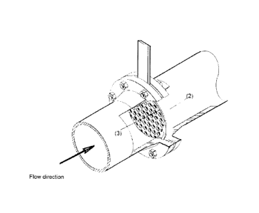
4. Brief Description of the Drawings
Fig. 1. illustrate the device with its upstream and downstream
perforated plates
Fig.-01(a): illustrate the perforated pressure conditioner plate
Fig.-01(b): illustrate the perforated flow conditioner plate
Fig.-02: illustrate the conventional valve with upstream device
and valve differential pressure
Fig.-03: illustrate the installation of the compact device in valve
inlet flange
Fig.-04: shows installation of the device into raised face flange
Table.-01: shows Sigma index calculations with examples of
valve pressure differential
Table.-02: shows examples of pressure restriction plate
differential pressures against Sigma index
Table.-03: shows examples of the restriction plate sizing for
plate differential pressure and maximum flow capacity.
5. Detailed Description
Referring now to FIG.-01, the apparatus comprises of following
construction parts:
(1) Upstream pressure restriction conditioner plate
(2) Downstream flow restriction conditioner plate
(3) Ring maximum thickness 3.0 inch with flow passage
The present invention is a paddle type steel device
8
CA 2870564 2017-07-13
comprises two perforated restriction plates (1) and (2) whereas
both plates are attached to the ring (3), as shown in FIG.01
Both pressure and flow conditioners plates acts to
dissipate fluid energy to provide a normal conditioned
process fluid to the conventional control valve inlet. The inlet
perforated restriction plate (1) has array of one size holes
(4) and the outlet restriction plate (2) has smaller size
perforations (5).
The plates are separated from each other by insufficient flow
run flow passage to avoid pressure recovery of fluid exit the
first plate. In a first embodiment, the pressure conditioner
plate (1), FIG.-01(a) is made in arrays of one common size
perforations (4) which causes the fluid flow to be reconfigured
where the liquid pressure energy is dissipated by changing
the fluid pressure profile. The second perforated plate (2),
FIG.01(b) keeps the first plate outlet fluid flow pattern
mismatching with the first plate's flow pattern to create plurality
of different paths and irregularities in the flow profile through
the plate smaller size holes (5) to dissipate the velocity energy
and acoustic noise level generated by the first plate's holes
before entering the valve for protection of the valve trim from
direct fluid impingement impact. The difference in the diameters
of the hole plates between 40-50% of the large hole diameter.
In a second embodiment referring to FIG.-02, the device
installed upstream of the control valve (6) at valve inlet flange
9
CA 2870564 2017-07-13
CA 2870564 2017-04-24
designed to create a predetermined differential pressure (7)
to reduce the inlet pressure so that a normal differential
pressure across the valve (8) can be achieved and
consequently avoid transformation of the liquid to vapor and
eliminate the direct impingement of the liquid on valve trim and
body, means that the reduced outlet pressure (P2) is the
inlet pressure to the valve, and the new differential pressure
across the valve (8) will satisfy the condition of eliminating
the cavitation effect, since the outlet pressure will be above the
liquid vapor pressure and the control valve is prepared to
operate in a more normal process condition.
Referring now to Table-01, the cavitation can be measured
and controlled by calculating the
cavitation index, called
Sigma (a) which is = P1-Pv/P1-P2, where Pv is the liquid vapor
pressure and (P1-P2) is the differential pressure across the
valve (AP). Higher the Sigma index value means lower value of
the differential pressure across the valve, and lower cavitation
effect on the valve, which further means that the main reason of
cavitation is the high pressure across the valve, therefore the
first restriction plate is used to achieve lower outlet pressure of
the plate which is the inlet pressure to the valve (6), resulted in
low differential pressure (8) across the valve.
As a result in the example shown in Table-01 for different static
inlet pressure and valve differential pressure (AP) , the valve
with a cavitation index of 1.7 and above, means that there is
CA 2870564 2017-04-24
no cavitation exist, while the valve under higher differential
pressure, with a cavitation index of 1.51 to 1.0 are subjected to
severe cavitation, whereas valves with a cavitation index of
1.51 -1.69, means that the valve is under cavitation
impact, the valve trim should be replaced by harder material,
the higher the hardness, the greater the resistance, such
material as Hestalloy C, 321 or 347 stainless steel, Monel,
Tungsten, or stellated face plug and seat, material of which
should match the type of fluid whether corrosive or not.
Referring to Table-02, the example of different high static
inlet pressures shows that the first restriction plate should be
sized to absorb a differential pressure of
¨for example
300psi- in order to achieve a cavitation index of 1.7 and above
to run the valve under normal process condition.
Table.-03 shows that, in order to achieve the above
requirement, the said plate should be checked and calculated
to ensure handling different inlet static pressures along with
high cavitation index. The plate Beta ratio (p) and bore
diameter are calculated to obtain the plate opening area which
should handle the process condition shown in the example
taking in consideration that the said area must handle the valve
maximum flow rate capacity with extra flow capacity of 25-33%
of valve rated capacity to provide sufficient valve's plug travel.
The restriction plate (2) bore diameter and bore area are sized
based on a single bore concentric plate, with the
calculated bore area is equal to the total perforations (holes)
area, and the number of the plate's holes equal to the
bore area divided by the area of the plate hole. Further
11
CA 2870564 2017-04-24
embodiment, the fluid stream flow path passing through the
first perforated plate (1) is subdivided by the perforations. The
extremely high pressure fluid exit the said plate generates
noise and high jet velocity due to harmonic interaction between
the hole downstream of the plate. As fluid exit through each
hole (4), the fluid accelerates due to the restriction of the
inside walls of the said holes and initiates a high speed stream
fluid, and expand to meet the downstream flow conditions.
The fluid jets downstream of
the first plate is detrimental
aspect of valve trim and body internals if direct impingement
of the liquid high velocity energy - exit the holes of first plate -
is subjected to the valve. The high fluid velocity and severe
noise generation of the perforated plate should be taken in
consideration in perforated restriction plates, therefore there is
a need for a second perforated plate (2) with array of smaller
diameter perforation (5) in opposite of the first plate's holes
axial direction in which the jet velocity vortices are
disturbed and the velocity energy is conditioned due to the
change of the flow pattern and subdividing the flowing fluid
streams exit the first plate (1) means that the fluid encounters
the second plate - which act as baffles - deflected the said
stream to each side and flows between adjacent holes toward
the next row of holes, and flow through passages that create a
high energy loss and pressure drop due to irregular and
opposite stream passages directions. This process
continues, and the pressure is reduced by friction with the walls
and by the frequent change in directions which finally
dissipate the fluid high velocity energy and
12
consequently reduces the
noise level before entering the
valve without shock waves since the void between the two
restriction plates act as packed muffler. A previous attempts
to silence
perforated plate noise have been only partly
successful, U.S. Patent Application 20040055816 by James
Gallagher et al, published in March 25, 2004, an apparatus for
filtering ultrasonic noise within a fluid flow system, the method
attenuates the noise propagating between a noise source and a
reference point in the flow stream (wherein the reference
point and the noise source are positioned in the flow stream in
direct acoustic line of sight relation). The method includes
positioning an absorbent element in the flow stream between
the noise source and the reference point.
Referring to FIG.-03, The device is sandwiched between
upstream valve flange faces without pipe cutting, or welding,
with new flange gaskets, the conditioner plates type and
pressure rating shall be in accordance with flange type either
RF raised f-ace or RTJ ring. type join+, flange, the maximum
valve flange faces separation distance required to insert
the device is 2.5-3.0
inch, this can be achieved by
simple pipe fitter's tools, however attention must be paid to
ensuring that the flange faces are parallel to the ring on both
sides, and not angled. The new flange
sp,reading use
unique technology
at present for safe spreading flange
faces a distance of 5.5 - 8.5 inch. The
restriction
plates, pressure rating, material, and dimensions in
1 3
CA 2870564 2017-09-11
CA 2870564 2017-04-24
accordance with the standard specifications of AGA., ISA.,
ASME., API., and ISO.
6. Patent Citation
Citation No. Title Names Date line No.
US20060096650 Non-linear noise suppressor Sawchuk Blaine 0 May 11,2006 28-
31
for perforated plate flow
conditioner
use perforated plates installed in
pipeline in front of the flow meter
cause the fluid flow to be reconfigured
U.S.5,762,107 Flow conditioner Den Norske Stats Jun 9,1998 3-4
The conditioner comprises a plate
arranged perpendicular to the flow
having apertures which are located
so as to distribute the flow radially
US3,513,864 High pressure fluid control means Self Richard E May 26,1970
3-4
Using disks inside the valve, where
pressure fluid is dissipated by subdivision
in a skeletal disk baffle grid assembly into
a plurality of tortuous courses
US 2021079 A Restricted flow device Crosley Radio Corp. Nov 12,1935 3-4
control the flow of liquefied refrigerant
from the condenser in a refrigerating
device to the evaporator
US2007110712 Non-linear noise suppressor Blaine
D.Sawchuk Mar 13, 2008 1-3
A flow conditioner for use in a pipeline
to be used in conjunction with a flow
meter. The flow conditioner uses alternating
hole sizes to reduce ultrasonic noise produced
by high flow rates
US5819803A Fluid pressure reduction device Kim W. Lebo Oct 13, 1998
1-2
A fluid pressure reduction device includes
a plurality of flow resistance modules to
provide tortuous flow paths within the valve
by using disks.
US3722854A Valve with perforated ribbon Grove Valves Mar 27,1973
15-30
silencing element
coiled ribbon of sheet material wrapped
into a plurality of layers inside the valve
resultant high energy loss greatly reduces
the average velocity and, hence, the sound level
14
CA 2870564 2017-04-24
US3856049A Multiple stage restrictor Leslie Co Dec 24,1974 1-3
A multiple stage restrictor is characterized
by a plurality of stacked plates inside a valve
to relatively decreases velocity by restricting
passages through which the fluid flows
US5390896A Energy loss device Control Components Inc. Feb 21,1995 2-4
A valve utilizing the energy loss by series of
Stacks for fluid flow paths and plurality of
members joined together for energy loss
US4221037A Method for manufacturing a fluid Copes-Vulcan, Inc. Sep 9,1980
3-5
control device with disc-type
flow restrictor
Valve trim includes a novel form of flow restrictor,
which serves to limit flow velocity and causes
fluid pressure to be reduced in a sufficient number
US3514074A High energy loss fluid control Self Richard E May
26,1970 2-15
velocity control of high pressure flowing
fluids and attain energy losses or high
pressure drop by using passage disks
within the valve