Note: Descriptions are shown in the official language in which they were submitted.
CA 02870635 2016-11-28
DEVICE FOR PERFORMING A DIAGNOSTIC TEST AND METHODS FOR
USE THEREOF
RELATED APPLICATIONS
[0001] This application claims the benefit of and priority to U.S. Prov.
Pat. App. Ser.
No. 61/625,368 filed 17 April 2012 and U.S. Prov. Pat. App. Ser. No.
61/740,975 filed 21
December 2012.
BACKGROUND
[0002] Sampling and testing of biological samples and body fluids (e.g.,
saliva, blood,
urine, fecal matter, foods, plants, fish, minerals, animals, etc) is common
for both testing
and monitoring humans, fish, animals, and plants for any number of biochemical
or
physiological conditions and, of course, for determining the general state of
health of an
organism. For example, sampling and testing of human body fluids is often
performed
for point-of-care testing ("POCT"). POCT is defined as medical testing at or
near the site
of patient care. The driving notion behind POCT is to perform and provide the
test
conveniently and immediately to the patient. This increases the likelihood
that the
patient, physician, and care team will receive the results more quickly and
allows for
immediate clinical management decisions to be made. POCT examples include, but
are
not limited to, blood glucose testing, metabolic testing (e.g., thyroid
stimulating
hormone), blood gas and electrolytes analysis, rapid coagulation testing,
rapid cardiac
markers diagnostics, drugs of abuse screening, urine testing, pregnancy
testing, fecal
occult blood analysis, food pathogen screening, hemoglobin diagnostics,
infectious
disease testing, cholesterol screening, cancer testing (e.g. PSA), hormone
testing (hCG,
LH, FSH), cardiac (troponin), pulmonary, gastroenterology (e.g., H. pylori
antibodies),
urology, dermatology, neurology, pediatrics, surgical, and public health
(Ebola, cholera,
HIV), testing and combinations thereof.
[0003] One testing method that is often employed for POCT and more
conventional
testing involves the use of lateral-flow chromatographic immunoassay
cassettes. Lateral-
flow chromatographic immunoassay cassettes can be used to easily and quickly
obtain a
variety of qualitative results relating to a number of biochemical and
physiological
conditions and disease states of an individual. These kinds of tests require
the end user to
simply add a sample to the cassette and then observe the result a few minutes
later. Since
such rapid and easy-to-use tests are user friendly, they are very popular in
both the
professional and consumer markets nowadays. Such tests are also widely used in
areas
- 1 -
CA 02870635 2016-11-28
where access to trained health care professionals is limited or where access
to proper
medical facilities is limited (e.g., poor areas, developing countries, war
zones, etc).
[0004] Lateral flow chromatographic immunoassay methods and devices have
been
described extensively. See, e.g., Gordon and Pugh, U.S. Pat. No. 4,956,302; H.
Buck, et
al., WO 90/06511; T. Wang, U.S. Pat. No. 6,764,825; W. Brown, et al., U.S.
Pat. No.
5,008,080; Kuo and Meritt, US 6,183,972, EP 00987551A3. Such assays involve
the
detection and determination of an analyte substance that is a member of a
specific binding
pair consisting of a ligand and a receptor. The ligand and the receptor are
related in that
the receptor specifically binds to the ligand, being capable of distinguishing
a specific
ligand or ligands from other sample constituents having similar
characteristics.
Immunological assays involving reactions between antibodies and antigens are
one such
example of a specific binding assay. Other examples include DNA and RNA
hybridization reactions and binding reactions involving hormones and other
biological
receptors. One well-known commercial embodiment of this technique is the
Clearblue
One-Step Pregnancy Test.
[0005] Lateral flow chromatographic immunoassay test cassettes have a
number of
desirable characteristics including their ease of use and broad applicability
to a variety of
analytes. Likewise, immunoassay procedures capable of being carried out on a
test strip
and which can be administered in the field or other locations where medical
testing
laboratories are not readily available have provided a great benefit to the
diagnosis and
control of disease. Currently, however, such lateral flow chromatographic
immunoassay
tests are generally only capable of providing qualitative results. That is,
while currently
available lateral flow chromatographic immunoassay test cassettes and cassette
reader
apparatuses are particularly well-suited for telling a practitioner whether or
not one or
.. more test substances are present in a sample above a given detection limit,
they are poorly
suited for providing quantitative results. There is an ongoing need in the art
for devices
and methods that combine the ease of use characteristics of lateral flow
chromatographic
immunoassay tests with systems that are designed to provide quantitative
results. Such
devices and methods may, for example, allow medical practitioners to diagnose,
monitor,
.. and manage a variety of conditions at the point of care (e.g., chair-side
or essentially
anywhere in the world) without being tied to a medical facility or a testing
laboratory.
BRIEF SUMMARY
[0006] Devices and methods for performing point of care diagnostic tests
for
detecting and quantifying at least one analyte in a biological sample (e.g., a
body fluid).
- 2 -
CA 02870635 2016-11-28
4
Disclosed herein are assay cassettes and testing devices that can be used to
provide rapid,
accurate, affordable laboratory-quality testing at the point of care. Such
assay cassettes
and testing devices are designed to provide rapid, quantitative test results
in a point-of-
care setting or the like where, in the past, only qualitative or semi-
quantitative results
have typically been available. Likewise, such assay cassettes and testing
devices may
eliminate or replace expensive, centralized clinical testing equipment and
technical
personnel. Such testing devices may include automated data reporting and
decision
support.
100071 In one embodiment, a diagnostic test system is disclosed. The
system includes
a lateral-flow chromatographic assay cassette and a compact, portable testing
device that
includes data collection and data analysis capabilities. The testing device is
configured to
interface with and analyze output of the lateral-flow chromatographic assay
cassette.
100081 In one embodiment, the lateral-flow chromatographic assay
cassette may
include a capture ligand capable of capturing and localizing at least one
analyte of interest
in a sample on an analysis surface of the lateral-flow chromatographic assay
cassette, at
least one reporter configured for interacting with at least one of the analyte
of interest or
the capture ligand, and at least a first calibration standard and a second
calibration
standard configured to provide at least a two-point calibration curve.
[00091 In another embodiment, the lateral flow chromatographic assay
cassette may
include a test strip and a separate calibration strip. In this embodiment of a
lateral flow
chromatographic assay cassette, a test sample (i.e., a sample containing an
unknown
amount of an analyte of interest) may be run in parallel with a calibration
standard (i.e., a
sample containing a known amount of the analyte of interest). The response to
the known
amount of the analyte of interest in the calibration standard on the lateral
flow
immunoassay device may be used to generate a calibration curve that can be
used to
quantify the amount of the analyte of interest in the test sample.
[00101 The lateral flow chromatographic assay cassette that includes a
test strip and a
separate calibration strip cassette may include a base, an absorbent test
strip for analyzing
an analyte of interest in an experimental sample positioned above the base,
and an
absorbent calibration strip for running at least one calibration standard
positioned above
the base in proximity to the absorbent test strip. The device further includes
a first
sample application zone positioned between a distal end and a proximal end the
first
absorbent strip, and a second sample application zone positioned between a
distal end and
a proximal end of the second absorbent strip. A volume of a liquid test sample
applied to
- 3 -
CA 02870635 2016-11-28
the first sample application zone and a volume of a liquid calibration
standard applied or
deposited to the second sample application zone each diffuse (i.e., wick)
through their
respective absorbent strips from the distal end to the proximal end.
Accordingly, the
analyte of interest, if present in the experimental sample, and the
calibration standard
interact with at least a first reporter (e.g., an antibody) immobilized on the
first and
second absorbent strips to yield a detectable signal.
100111 The
testing device includes a testing apparatus that is configured for collecting
data from the lateral-flow chromatographic assay cassette. In one embodiment,
the
testing device includes a testing apparatus that is configured to be
physically coupled to a
handheld device (e.g., a smartphone). The testing apparatus couples the
lateral-flow
chromatographic assay cassette to the handheld device in proximity to a light
source, the
light source being capable of transmitting at least one wavelength of light
configured to
yield a detectable signal from the reporter(s), and a detector positioned to
capture the
detectable signal from the reporter(s). In another embodiment, the testing
apparatus may
.. be a stand-alone device that includes its own light source, optics, data
capture capabilities,
and the like. In such an embodiment, the testing apparatus may be configured
to collect
assay data from an assay cassette and transfer it to a handheld device (e.g.,
a smartphone)
for analysis and reporting.
[0012] In
addition, the system described herein may include an interpretive algorithm
stored in a computer readable format and electronically coupled to a handheld
device,
wherein the interpretive algorithm is configured to (i) calculate a
calibration curve based
on at least one of a the first calibration standard and the second calibration
standard or a
known amount of an analyte of interest and a blank region and then (ii)
convert the
detectable signal from the reporter(s) to a numerical value related to the
presence or
amount of the at least one analyte present in a sample. The interpretive
algorithm may be
included in an on-board computing system of the handheld device or the
interpretive
algorithm may be stored remotely in a computer storage medium that is
accessible by the
handheld device.
[0013] In
another embodiment, a method for detecting at least one analyte of interest
in a sample is disclosed. The method includes (I) providing a lateral-flow
chromatographic assay cassette as described herein above, (2) providing a
testing device
as described herein above, and (3) applying a liquid sample that includes at
least one
analyte of interest to the lateral-flow chromatographic assay cassette. The
method further
includes (4) inserting the lateral-flow chromatographic assay cassette into
the testing
- 4 -
CA 02870635 2016-11-28
apparatus, (5) illuminating the lateral-flow chromatographic assay cassette
with the light
source of the handheld device in order to yield a detectable signal from the
reporter(s),
and (6) querying the interpretive algorithm for (i) calculating the
calibration curve and
then (ii) converting the detectable signal from a first reporter to a
numerical value related
to the presence or amount of the at least one analyte present in a sample.
100141 These and other objects and features of the present invention will
become
more fully apparent from the following description and appended claims, or may
be
learned by the practice of the invention as set forth hereinafter.
BRIEF DESCRIPTION OF THE DRAWINGS
[0015] To further clarify the above and other advantages and features of
the present
invention, a more particular description of the invention will be rendered by
reference to
specific embodiments thereof which are illustrated in the appended drawings.
It is
appreciated that these drawings depict only illustrated embodiments of the
invention and
are therefore not to be considered limiting of its scope. The invention will
be described
and explained with additional specificity and detail through the use of the
accompanying
drawings in which:
[0016] Figure 1 illustrates a perspective view of a diagnostic test
system, according to
one embodiment of the present disclosure;
[0017] Figures 2A and 2B illustrates a lateral flow immunoassay device
according to
one embodiment of the present invention;
[0018] Figures 3A and 3B illustrates a lateral flow immunoassay device
according to
another embodiment of the present invention;
[0019] Figure 4A illustrates a plan view of a diagnostic test system that
includes a
digital camera device and a testing apparatus configured to couple the lateral-
flow
chromatographic immunoassay cassette to the digital camera device;
[0020] Figure 4B illustrates a side view of the diagnostic test system of
Figure 4A;
[0021] Figure 5A illustrates an exploded view of the diagnostic testing
system that is
illustrated in Figures 4A and 4B;
[0022] Figure 5B illustrates a view of a component of the diagnostic test
system
shown in Figure 5A, wherein the component includes a light sealing feature;
[0023] Figure 6 illustrates a view of a diagnostic test system that
includes an indexing
feature for aligning the digital camera device and the testing apparatus;
- 5 -
CA 02870635 2016-11-28
[0024] Figure 7A is a cut-away view of a testing apparatus of a
diagnostic test system
illustrating a target device configured for normalizing and/or calibrating the
light source
and the detector of the diagnostic test system;
[0025] Figure 7B is a cut-away view of a testing apparatus of a
diagnostic test system
illustrating a mechanical interlock feature configured to interlock with a
corresponding
second mechanical interlock feature on a lateral-flow chromatographic assay
cassette;
[0026] Figure 8 illustrates a lateral-flow chromatographic assay cassette
packaging
system that includes a tracking feature readable by the handheld device;
[0027] Figure 9 illustrates a two point calibration curve according to
one embodiment
of the present disclosure; and
[0028] Figure 10 is a decision tree schematically illustrating a decision
support
algorithm according to one embodiment of the present disclosure.
DETAILED DESCRIPTION
[0029] Devices and methods for performing point of care diagnostic tests
for
detecting and quantifying at least one analyte in a biological sample (e.g., a
body fluid).
Disclosed herein are assay cassettes and testing devices that can be used to
provide rapid,
accurate, affordable laboratory-quality testing at the point of care. Such
assay cassettes
and testing devices are designed to provide rapid, quantitative test results
in a point-of-
care setting or the like where, in the past, only qualitative or semi-
quantitative results
have typically been available. Likewise, such assay cassettes and testing
devices may
eliminate or replace expensive, centralized clinical testing equipment and
technical
personnel. Such testing device may include automated data reporting and
decision
support.
[0030] In one embodiment, a diagnostic test system is disclosed. The
system includes
a lateral-flow chromatographic assay cassette and a testing device that
includes data
collection and data analysis capabilities. The testing device is configured to
interface
with and analyze output of the lateral-flow chromatographic assay cassette.
I. Diagnostic Test Systems
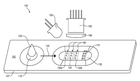
100311 Referring to Figure 1, perspective view of a diagnostic test
system 100 is
.. illustrated. The diagnostic test system 100 includes a lateral-flow
chromatographic assay
cassette 105 and means for collecting assay data from the lateral-flow
chromatographic
assay cassette 105.
[0032] The lateral-flow chromatographic assay cassette 105 includes a
plastic housing
107 containing a test strip, which is generally a plastic strip laminated with
porous
- 6 -
CA 02870635 2016-11-28
material that permits lateral flow of liquid. The illustrated lateral-flow
chromatographic
immunoassay cassette 105 includes a sample application zone 110 and an
analysis zone
130.
[0033] When a sample 120 is applied to the lateral-flow chromatographic
.. immunoassay cassette 105 at the sample application zone 110, the sample 120
diffuses
through the strip in flow direction 125 toward the analysis zone 130. In the
embodiment
illustrated in Figure 1, the analysis zone 130 includes a test line 140 that
includes at least
one capture ligand selected for capturing at least one analyte of interest in
the sample 120.
The analysis zone 130 further includes at least first and second calibration
standard lines
150a and 150b. Additionally, the analysis zone may include a positive control
line 170
that may be configured to provide an indication regarding whether or not
sample has
diffused though the strip and whether or not the assay is functioning. For
example, the
positive control line 170 may include a water soluble dye that is positioned
and
configures to indicate that the sample has flowed the length of/ travered the
test strip.
[0034] The analyte(s) of interest, the first and second calibration
standards, and the
positive control can be detected on their various target lines, 140, 150a,
150b and 170,
respectively, with various reporters. The reporters 160 for each of the
various target
lines, 140, 150a, 150b and 170, may be the same or different. Examples of
suitable
reporters include, but are not limited to, visible and fluorescent dyes, latex
beads,
enzymes, gold nanoparticles, silver nanoparticles, titanium nanoparticles,
europium
fluorophores, quantum dots, and the like. Quantum dots are nano-scale
materials that can
produce excited emission at particular wavelengths depending on their size and
shape.
Quantum dots can be used in immunoassays where dyes have traditionally been
used.
However, quantum dots are generally superior to traditional organic dyes on
several
counts: quantum dots are typically much brighter that organic dyes (owing to
their high
extinction coefficients combined with a comparable quantum yield to
fluorescent dyes) as
well as their stability (i.e., much less photobleaching). For example, it has
been estimated
that quantum dots are 20 times brighter and 100 times more stable than
traditional
fluorescent reporters.
[0035] Emission from the various reporters can be excited by a number of
sources. In
the illustrated embodiment, an LED light source 180 is used illuminate the
analysis zone
130 of the lateral flow assay cassette 105. Illumination by the light source
180 may
produce a detectable signal that includes at least one of emission (e.g.,
fluorescence),
color, reflectance, diffuse scattering (i.e., scattering and absorbance),
elastic light
- 7 -
CA 02870635 2016-11-28
p
scattering, chemiluminescence, chemifluorescence, transmission, plasmon
surface
resonance, or absorbance from the reporters. A lens 190 (e.g., a collimating
lens) and a
detector 195 (e.g., a CCD or CMOS camera) are used to collect data from the
reporters
and the first and second calibration standards.
[0036] When the sample 120 is applied to the diffusion strip of the lateral-
flow
chromatographic assay cassette 105, the liquid in the sample carries the
analyte of interest
through the diffusion strip in flow direction 125 into the analysis zone 130
where it can be
captured by the capture ligand line 140. The first and second calibration
standard lines
150a and 150b are selected to provide a detectable signal that correlate to
non-zero
concentration values of the analyte of interest. For example, the first and
second
calibration standard lines 150a and 150b may include an amount of the analyte
of interest
or another material pre-bound to the diffusion strip of the lateral-flow
chromatographic
assay cassette 105. The reporter 160 may be a diffusible material that can
bind to the
capture ligand line 150 and the first and second calibration standards 150a
and 150b in an
amount proportional to the amount of bound ligand is present in each line. In
response to
illumination by the light source, the reporter 160 bound to each of lines 140,
150a, and
150b provides a signal that can be used to calculate a calibration curves and,
in turn,
determine the concentration of the analyte of interest in the sample 120. A
more detailed
discussion of methods for deriving analyte concentration from the data of the
first and
second calibration standards 150a and 150b and the capture line 140 is
discussed in
greater detail elsewhere herein.
[0037] In one type of lateral-flow chromatographic immunoassay
cassette, the test
strip is divided into four domains, which can be made of only one kind of
material or
several kinds of material (e.g., up to four different kinds of materials). The
first domain is
for sample addition. It functions to remove viscous and particulate materials
in the
sample and also to condition the sample solution for the reactions in the
following
domains. The second domain is a mobile-phase with a color conjugate. In one
embodiment, the color conjugate may be made from conjugation between a visible
color
marker (e.g., colored beads, colloidal gold, fluorescent dyes, etc.) and a
detection
antibody. The detection antibody can bind a specific antigen in the sample
(e.g., an
analyte of interest or a positive control substance) and forms an antigen-
color conjugate
complex. The third domain of the lateral-flow chromatographic immunoassay
cassette is
a solid-phase with immobilized capture antibody. The capture antibody can bind
the
antigen of the antigen-color conjugate complex and forms capture antibody-
antigen-color
- 8 -
CA 02870635 2016-11-28
conjugate complex sandwich. The fourth domain is for solution absorption. It
draws
sample solution towards it continuously.
[0038] During the testing, sample added to the first domain flows to the
second
domain. If the antigen is present in the sample, it will bind the color
conjugate to form
antigen-color conjugate complex. This complex then migrates to the third
domain to bind
the capture antibody and forms the capture antibody-antigen-color conjugate
complex
sandwich. Since the capture antibody is immobilized in the third domain, the
sandwich
shows as a visible color signal or a fluorescent signal, depending on the dye
type, on the
site of the capture antibody. If there is no antigen in the sample, no
sandwich can be
formed and hence no visible color signal can be seen in the third domain. This
is a so-
called non-competitive immunoassay or a sandwich assay where the amount of
signal is
directly proportional to the concentration of the analyte of interest in the
sample.
[0039] Lateral-flow chromatographic immunoassay cassettes can also be
adapted for
competitive immunoassays. In a competitive immunoassay, the analyte of
interest in the
unknown sample competes for binding to an antibody with a labeled analyte. In
a
competitive assay, the labeled analyte is able to provide a known signal. In
the assay, the
amount of labeled analyte bound to the antibody is measured and any reduction
in the
known signal is attributed to the presence of the analyte in the sample. That
is, in this
method, the response will be inversely related to the concentration of analyte
in the
unknown. This is because the greater the response, the less antigen in the
unknown was
available to compete with the labeled antigen.
[0040] Lateral-flow chromatographic immunoassay cassettes may be adapted
for
assaying a number of different analyte types. For example, immunoassay
cassettes have
been adapted or may in the future be adapted for blood glucose testing,
metabolic testing
(e.g., thyroid stimulating hormone), blood gas and electrolytes analysis,
rapid coagulation
testing, rapid cardiac markers diagnostics, drugs of abuse screening, urine
testing,
pregnancy testing, fecal occult blood analysis, food pathogen screening,
complete blood
count ("CBC"), hemoglobin diagnostics, infectious disease testing (e.g., a
multi-analyte
rapid diagnostic test for detecting malaria infection), cholesterol screening,
hormone
testing, cardiac pulmonary, gastroenterology, urology, renal, dermatology,
neurology,
pediatrics, surgical, public health, and veterinary and plant pathology
testing,
combinations thereof, and the like.
100411 In addition to the foregoing, another embodiment of a lateral flow
immunoassay cassette is described. Examples of such lateral flow immunoassay
cassettes
- 9 -
CA 02870635 2016-11-28
are shown at 200 in Figures 2A and 28 and at 300 in Figures 3A and 3B. In the
lateral
flow immunoassay cassettes 200 and 300, a test sample (i.e., a sample
containing an
unknown concentration of an analyte of interest) may be run in parallel with a
calibration
standard (i.e., a sample containing a known concentration of the analyte of
interest). The
response to the known concentration of the analyte of interest in the
calibration standard
on the lateral flow immunoassay device may be used to generate a calibration
curve that
can be used to quantify the amount of the analyte of interest in the test
sample.
[0042] Such an arrangement may provide superior results. For example, the
test and
calibrations strips of such cassettes may be manufactured side-by-side under
substantially
to equal temperature and humidity conditions. As a result, it is generally
the case that the
test and calibrations strips each have the same amount on antibody immobilized
thereon
and that the antibody on each will react substantially the same. Also, because
the test and
calibration assays are run in parallel, the test and calibration results are
generally
unaffected by factors like temperature and humidity. This is generally not the
case if the
test and calibration assays are run at separate times on strips that may have
been
manufactured at different times. Likewise, because the test and calibration
assays are run
in parallel, the cassettes and a reader device, if used, are calibrated for
each assay run on
each cassette, which is believed to provide more reliable quantitative
results.
[0043] The lateral flow immunoassay cassette 200 illustrated in Figures
2A and 2B
includes a base 214 that includes a test strip 201a and a calibration strip
201b. The test
strip 201a includes a sample application zone 202a with a sample collection
pad 216a, a
conjugate pad 204a, a test assay strip 206a (e.g., a nitrocellulose ("NC")
membrane), and
an absorbent pad 212. Likewise, the calibration strip 201b includes a sample
application
zone 202b with a sample collection pad 216b, a conjugate pad 204b, a
calibration strip
206b, and the absorbent pad 212. Each of the test assay strip 206a and the
calibration
strip 206b include at least one capture binding moiety 208a and 208b (e.g., an
antibody, a
nucleic acid, or the like) that can specifically interact with and capture the
analyte of
interest for detection. In one embodiment, the sample pad 212 may include flow
indicator
lines 210a and 210b (e.g., a water soluble dye) that indicate whether or not
sample has
successfully diffused through the test strip 201a and the calibration strip
201b.
[0044] In the illustrated embodiment, the test 201a and calibration
strips 201b are run
in opposite directions (i.e., both the test sample and calibration standard
flow toward
absorbent pad at the center of the cassette). In other embodiments, the test
and calibration
strips may be arranged such that the test sample and calibration standard flow
parallel to
- 10 -
CA 02870635 2016-11-28
one another. Such an embodiment may, for example, include a divider arranged
between
the test assay strip and the calibration assay strip.
100451 The lateral flow immunoassay cassette 300 illustrated in Figures
3A and 3B is
similar to the cassette 200 of Figures 2A and 2B. The lateral flow immunoassay
cassette
300 includes a base 314 that includes a test strip 301a and a calibration
strip 301b. The
test strip 301a includes a sample application zone 302a with a sample
collection pad 316,
a conjugate pad 304a, a test assay strip 306a (e.g., a nitrocellulose ("NC")
membrane),
and an absorbent pad 312. In addition, the test strip 301a includes includes a
sachet 320
(e.g., a blister pack) of buffer that can be used to chase (i.e., wash) a test
sample through
the conjugate pad 304a and the assay strip 306a toward the absorbent pad 312.
[0046] In contrast to the cassette 200 of Figures 2A and 2B, the cassette
300 omits a
calibration standard application zone and instead includes a standard solution
sachet 318
that contains a known volume of a solution that contains a known amount of at
least one
analyte of interest. When the a standard solution sachet 318 is pierced at the
time of use,
.. the solution wicks through the conjugate pad 304b and the calibration strip
306b toward
the absorbent pad 312. Each of the test assay strip 306a and the calibration
strip 306b
include at least one capture binding moiety 308a and 308b (e.g., an antibody,
a nucleic
acid, or the like) that can specifically interact with and capture the analyte
of interest for
detection. The characteristics of the standard solution sachet 318 can be used
to test for
quantitative delivery of the calibration standard onto the calibration strip
306b and to test
the response of the capture binding moiety 308b to the analyte of interest. In
one
embodiment, the sample pad 312 may include flow indicator lines 310a and 310b
(e.g., a
water soluble dye) that indicate whether or not sample has successfully
diffused through
the test strip 301a and the calibration strip 301b.
[00471 In one embodiment, the sample pad 216a, 216b, or 316 may be
configured to
absorb and dispense a predetermined amount of a fluid from the fluid that is
applied
thereto. That is, the sample pad 216a, 216b, or 316 may be fabricated from an
absorbent-
type material that may saturated with fluid and then when, for example, the
sample pad
216a, 216b, or 316 is compresses or squeezed, the sample pad 216a, 2166, or
316 can
dispense a predetermined amount of a fluid therefrom. In one embodiment, the
sample
pad 216a, 216b, or 316 may be made of cellulose, glass fiber or other material
where the
fluid sample is applied to the lateral flow device and, if necessary modifies
it to improve
the results of the assay. This might be by modifying pH, filtering out solid
components,
- 11 -
CA 02870635 2016-11-28
separating whole blood constituents, adsorbing out unwanted antibodies or some
other
test specific variable.
[0048] For some applications, the sample pad 216a, 216b, or 316 may be
pretreated
by dipping it into a specific buffer containing a mix of a solution comprised
of soluble
proteins, surfactants/detergents, and other polymers. These may allow for a
steady flow
and prevent nonspecific binding of sample components to the pad 216a, 216b, or
316.
[0049] In some embodiments, the sample may be added to the sample pad
216a,
216b, or 316 by collecting a liquid sample (e.g., blood, urine, or saliva) and
adding a
selected volume of the sample to the sample pad. In other embodiment, the
sample may
to .. be added to the sample pad 216a, 216b, or 316 by soaking the pad with a
fluid sample.
For example, the sample pad 216a, 216b, or 316 may be soaked with saliva by
inserting
the sample collection pad 216a, 216b, or 316 end of the device 200 or 300 into
the mouth
to collect a saliva sample.
[0050] In one embodiment, the conjugate pad 204a, 204b, 304a, 304b is
made of a
non-absorbent material such as fiberglass pad, polyester, rayon or a similar
material. The
conjugate pad 204a, 204b, 304a, 304b is typically fabricated from a synthetic
material (at
least when using a gold conjugate) to ensure the efficient release of its
contents.
[0051] As its name implies, the assay's detection conjugate (e.g.,
colloidal gold) is
dried down and held in place in the conjugate pad 204a, 204b, 304a, 304b until
a liquid
test sample is applied to the sample pad. The liquid from the sample, by
capillary action
moves into the conjugate pad 204a, 204b, 304a, 304b, re-hydrates the dry
conjugate and
allows the mixing of the sample with the conjugate. The complex of conjugate
and
analyte then moves into and up the assay strip 206a, 206b, 306a, 306b.
Pretreatment of
the conjugate pad 204a, 204b, 304a, 304b helps to ensure the conjugate
releases at the
.. proper rate and enhances its stability. The pretreatment is performed in
the same way as
with the sample pad 216a, 216b, or 316.
[0052] In one embodiment, the at least one capture binding moiety 208a,
208b, 308a,
308b may be added to the test or calibration strips with a dispenser that
gently slides a
soft capillary tube across the membrane. A dispenser pump releases a constant
volume of
.. the reagents down the length of the membrane. This system is simple, easy
to use, and
low cost. They can be somewhat cumbersome in large scale manufacturing and
many
systems require a technician to constantly feed the nitrocellulose cards and
to monitor
reagent levels as well as the quality of the test and control lines.
- 12 -
CA 02870635 2016-11-28
[00531 An alternative method of applying the at least one capture binding
moiety
208a, 208b, 308a, 308b includes a non-contact aerosol system. These sprayers
dispense
solutions in controlled ultrafine, ultra- small volume aerosols. These devices
project very
fine droplets of reagent onto the membrane and overlap the drops to create a
continuous
line. Spraying offers much more control of the reagent application, but it
also adds
capital expense and increases the complexity of strip manufacturing. These
devices are
more appropriate in very large scale manufacturing or when a reader with tight
tolerances
will be used to analyze the lateral flow test strips.
[0054] In the foregoing, addition of one line of the at least one capture
binding moiety
208a, 208b, 308a, 308b onto each of the test or calibration strips is
discussed. However,
one will appreciate that a cassette 200 or 300 may include multiple test and
control lines
that may each be configured to interact with a different analyte of interest.
[0055] Referring now to Figures 4A and 4B, plan and side views of a
diagnostic test
system 240 are illustrated. In one embodiment, the diagnostic test system 240
may
include a handheld device 250 and a testing apparatus 260.
[0056] In the illustrated embodiment, the handheld device 250 is an
iPhoneTM.
However, the handheld 250 device can be essentially any cell phone device,
digital
camera device, or a similar device that has an onboard camera/image capture
function,
data collection and analysis capabilities, data and results display
capabilities, and,
preferably, the ability to communicate with one or more remote computer or
cellphone
networks for data upload, querying a data analysis algorithm, querying a
decision support
algorithm, and the like. In the illustrated embodiment, the handheld device
250 includes
a front-directed camera 280, a back-directed camera (not shown) that is
directed into the
testing apparatus, a display screen 290, and audio input and output ports 295a
and 295b.
The display screen 290 can be used for display of data and results. In
addition, the
display screen 290 may include touchscreen capabilities that can be used for
input of data
or commands. Additionally the front-directed camera can be used for imaging QR
and
bar code information identifying the test to be performed and providing lot
number,
expiration date, and control values as well as other parameters as needed for
test
identification, calibration, results interpretation, and data reporting.
[0057] In one embodiment, the testing apparatus 260 is designed to be
securely
coupled to the handheld device 250. For example, the testing apparatus 260 may
be
designed to fit a specific class or brand of handheld devices. The testing
apparatus
includes a cassette port 270 that is designed to allow an assay device, such
as a lateral
- 13 -
CA 02870635 2016-11-28
flow immunoassay cassette 105 (see Figure 1), to be inserted into the testing
apparatus
260. Additionally, an interior portion of the testing apparatus 260 may be
painted with a
flat black color so as to avoid extraneous and reflected light. In addition,
the testing
apparatus 260 includes a number of internal components (e.g., i/o ports, power
ports, light
source(s), lens(es), light conducting media, etc.) that are designed to
transform the
handheld device 250 into a device that can be used to collect and analyze data
produced
by an assay device, such as the lateral flow immunoassay cassette 105 (see
Figure 1).
[0058] While the testing apparatus 260, is shown fitted to the handheld
device 250,
one will appreciate that they testing apparatus can be configured as a
separate unit that
includes its own light source, power supply, optics, data capture
capabilities, and the like.
In such an embodiment, the testing apparatus may be configured to collect
assay data
from an assay cassette and transfer it (e.g., by a wired or wireless
connection, by
BluetoothTM, or the like) to the handheld device for analysis and reporting.
[0059] Referring now to Figure 5A, Figure 5A illustrates an exploded view
of the
diagnostic testing system 240 that is illustrated in Figures 4A and 4B. As can
be seen in
the exploded view, the testing apparatus 260 includes a main body housing 310
and an
assay housing 320.
[0060] The main body housing 310 is primarily designed to mate cleanly
with the
handheld device 250. For example, the main body housing 310 may be shaped such
that
the handheld device 250 can be slid into the main body housing 310 such that
the
handheld device 250 clicks into or otherwise securely mates with the main body
housing
310. The main body housing 310 may also include one or more gaskets, seals,
and the
like that allow the handheld device to form a secure and light-tight seal with
the main
body housing 310. Additional features of the main body housing 310 will be
discussed
.. below.
[0061] The assay housing 320 is fixedly coupled to the main body housing
310. In
the illustrated embodiment, the assay housing 320 includes a cassette port 270
that is
configured such that a lateral flow immunoassay cassette 105 can be inserted
into the
assay housing 320. In addition, the assay housing 320 in the in the
illustrated
embodiment includes a lens that is interposed between the handheld device's
250 back-
directed camera (not shown) and the lateral flow immunoassay cassette 105.
Likewise,
an optical fiber device or light pipe 340 that is capable of transmitting
light either to the
lateral flow immunoassay cassette 105 from the hand held device's 250 light
source (not
- 14 -
CA 02870635 2016-11-28
shown), from the lateral flow immunoassay cassette 105 to the hand held
device's 250
back-directed camera (not shown), or both.
[0062] While the hand held device's 250 light source (not shown) can be
used to
illuminate the lateral flow immunoassay cassette 105, the diagnostic testing
system 240
may also include one or more additional light sources that can be housed in
either the
assay housing 320 or the main body housing 310. Suitable examples of light
sources can
include, but are not limited to a camera flash, an autofocus illuminator on a
camera, an
LED light, an incandescent lamp, or a gas-discharge lamp. For example, the
light source
can come from micro-LED lamps that are included in the assay housing 320. The
micro-
.. LEDs can be selected to emit certain wavelengths that are adapted for one
or more assay
conditions. The micro-LEDs can be powered by drawing electrical power from the
battery of the handheld device 250. In addition, either the assay housing 320
or the main
body housing 310 may be configured such that ambient light or sunlight can be
used to
illuminate the lateral flow immunoassay cassette 105.
[0063] In one embodiment, at least one wavelength filter may be interposed
between
the light source and the lateral-flow chromatographic immunoassay cassette
105. For
example, if the assay is a fluorescent assay, then the wavelength filter may
be used to
yield a specific wavelength of light from the light source to excite
fluorescent emission
from the assay system. Likewise, certain colored dyes may yield a better
signal when
excited by selected wavelengths of light.
[0064] In one embodiment, the lens 330 (e.g., a collimating lens) may be
used for
focusing the light source on the lateral-flow chromatographic immunoassay
cassette 105.
For example, the lens 330 may be used to increase the amount of incident light
impinging
on the lateral-flow chromatographic immunoassay cassette 105. For instance,
the purpose
of the lens 330 may be to bring the focal point of the camera of the handheld
device 250
(which is limited to about 6 inches or more) to less than 2 centimeters. This
allows for a
smaller overall package and produces a finer image that prevents the use of
convoluting a
blurry picture using Fourier transforms in order to produce a usable data that
can be
analyzed. Furthermore, with a multi-analyte detection assay (e.g., two
calibration
standard lines and a test sample line), the finer image will prevent overlap
of the target
lines to improve sensitivity and accuracy. In another example, a focusing
apparatus may
be used to focus ambient light or sunlight on the analysis zone of the lateral-
flow
chromatographic immunoassay cassette 105.
- 15 -
CA 02870635 2016-11-28
[0065j In some embodiments, the assay cover 320 may include a device that
can
allow the angle of the lateral-flow chromatographic immunoassay cassette 105
to be
adjusted relative to the handheld device 250 and a light source (not shown).
By
selectively modifying these angles, the lower detection limit of the assay can
be extended,
the signal to noise ratio can be improved, etc. In one embodiment, the device
can be
adjusted manually in order to choose an angle that optimizes detection limit,
signal to
noise, and the like. In another embodiment, the device can be coupled to a
mechanical
means, such as a servo motor or a gel-damped spring device that can allow the
device to
automatically sample a number of angles while the handheld device 250 collects
data
from the lateral-flow chromatographic immunoassay cassette 105.
[0066] Referring now to Figure 5B, the assay housing 320 and the cassette
port 270
are illustrated in greater detail. In the embodiment illustrated in Figure 38,
the cassette
port 270 of the assay housing 320 includes a sealing gasket 350 disposed
around the
cassette port 270 that can seal the cassette port 270 when an assay cassette
105 is inserted
therein so that ambient light does not leak into the housing 260. For example,
if ambient
light leaks into the housing 260, it could skew results. In addition, the
cassette port 270
may include a spring-loaded flap (not shown) or similar means that can seal
ambient light
out of the housing 260 even when no cassette 105 is inserted into the cassette
port 270.
[0067] Referring now to Figures 6, 7A, and 7B, additional features of the
housing 260
are illustrated.
[0068] Referring to Figure 6, an example of an indexing feature that can
reliably align
the housing 260 relative to the handheld device 250 is illustrated. In the
illustrated
embodiment, the indexing feature may include a headphone jack 410 that is
integrated
into the housing body 310. When the handheld device 250 is inserted into the
housing
body 310, the headphone jack 400 is positioned such that it can be inserted
into the
headphone port 410 of the handheld device 250. It will be understood by
persons having
ordinary skill in the art that headphone jack 400 is but one example of an
indexing feature
and that additional indexing features can be employed without departing from
this
discussion.
[0069] In addition to aligning the housing body 310 relative to the
handheld device
250, the headphone jack 400 can be used to draw electrical power from the
handheld
device 250 in order to power components (e.g., one or more illumination
devices) that are
positioned in the housing 260. Likewise, the headphone jack 400 can be used
for data
transfer between the handheld device 250 and components in the housing 260.
- 16 -
CA 02870635 2016-11-28
[0070] Referring now to Figure 7A, a target device 500 is illustrated.
The target
device 500 can be used to normalize/calibrate the response of at least one of
the camera or
the light source of the handheld device. In one embodiment, the target device
may
located on an interior surface 325 of the assay housing 320 in close proximity
to the
cassette port 270 in an area that is can be illuminated by a light source that
will be
employed for illumination of an assay cassette and viewable by a camera of a
handheld
device that is going to be used to capture data from the cassette. For
example, the target
device may have a known color and/or color intensity that can give a known
response for
calibrating the light source and the camera. In addition, the target device
500 can be used
to -- to ensure that the light source and the camera are directed at the
proper point when the
handheld device in inserted into the housing.
[0071] Referring now to Figures 7A and 78, the assay housing 320 may
further
include a mechanical interlocking feature 510 that is positioned and
configured to mate
with a mechanical interlocking feature 520 on the assay cassette. For example,
the
-- mechanical interlocking features 510 and 520 may include tab and cut-out
features that
are designed to fit together. Such mechanical interlocking features 510 and
520 may be
used to ensure that the cassette 105 is inserted in to the assay housing 320
in the proper
orientation. In addition, such mechanical interlocking features 510 and 520
may be
coupled to a disabling feature that can shut down the device if an
incompatible cassette is
-- inserted into the housing 320 or if the cassette is inserted in the wrong
orientation. This
can, for example, be an important safety feature because it prevents the
device from
reading the wrong portion of the cassette and giving an erroneous reading as a
result.
H. Methods for Detecting At Least One Analyte of Interest in a Sample
[0072] In one embodiment, a method for detecting at least one analyte of
interest in a
sample is disclosed. The method includes providing a lateral-flow
chromatographic assay
cassette and providing a testing device that is capable of interfacing with
the lateral-flow
chromatographic assay cassette.
[0073] In an embodiment, the lateral-flow chromatographic assay cassette
may
include a capture ligand capable of capturing and localizing at least one
analyte of interest
in a sample on an analysis surface of the lateral-flow chromatographic assay
cassette, at
least one reporter configured for interacting with at least one of the analyte
of interest or
the capture ligand, and at least a first calibration standard and a second
calibration
standard configured to provide at least a two-point calibration curve. In
another
embodiment, a lateral-flow chromatographic assay cassette may include an
absorbent test
- 17 -
CA 02870635 2016-11-28
strip for analyzing an analyte of interest in an experimental sample and an
absorbent
calibration strip for running at least one calibration standard positioned in
proximity to
the absorbent test strip as described in greater detail elsewhere herein.
[0074] In one
embodiment, the lateral-flow chromatographic assay cassette may be
packaged in a packaging system 600, as illustrated in Figure 8. The packaging
system
600 includes a sealed package (e.g., a plastic-, foil-, or paper-based
package) that can be
used for containing, storing, or transporting the lateral-flow chromatographic
assay
cassette 610 in a clean and preferably sterile environment. A QR code decal or
sticker
with relevant cassette information could be applied or printed to the outside
of each foil
lo pouch or canister.
[0075] In
addition, the packaging system 600 includes a tracking code 630. In the
illustrated embodiment, the tracking code 630 is a QR code, which is a two-
dimensional
bar code. Two-dimensional bar codes, like QR codes, can be used to store far
more
information that can be stored in a conventional bar code. For example, a QR
code can
be used to store up ¨4300 alphnumeric characters (i.e., 0-9, A¨Z, space, $, %,
*, +, /,
:, etc.). In one embodiment, the tracking code 630 can be read by the
diagnostic testing
system prior to initiating a test. The tracking code may be used to store
information that
is relevant to the test in a format that can be read by the device. For
example, the tracking
code 630 can be used for recording and then transmitting to the test system
the values for
the calibration standards used on the lateral-flow chromatographic assay
cassette 610,
manufacturer, date of manufacture, lot number for the lateral-flow
chromatographic assay
cassette 610, manufacturer, date of manufacture, and sample/results tracking.
[0076] The
testing device may include a testing apparatus that is configured to couple
the lateral-flow chromatographic assay cassette to the handheld device in
proximity to a
light source, the light source being capable of transmitting at least one
wavelength of light
configured to yield a detectable signal from the reporter(s) (e.g., at least
one reporter
configured for interacting with at least one of the analyte of interest in a
test sample
and/or a calibration sample, the first calibration standard, and the second
calibration
standard), and a detector is positioned to capture the detectable signal from
the
reporter(s).
[0077] The
method may further include applying a liquid sample that includes at least
one analyte of interest to the lateral-flow chromatographic assay cassette. In
some
embodiments, applying a liquid sample to the cassette may include applying
separate test
and calibration samples to separate test and calibration strips. The method
may further
- 18-
CA 02870635 2016-11-28
include inserting the lateral-flow chromatographic assay cassette into the
testing
apparatus device, illuminating the lateral-flow chromatographic assay cassette
with the
light source of the testing device in order to yield a detectable signal from
the reporter(s),
and querying an interpretive algorithm for (i) calculating the calibration
curve and then
(ii) converting the detectable signal from the first reporter to a numerical
value related to
the presence or amount of the at least one analyte present in a sample.
[0078] In one embodiment, the calibration curve may be calculated based
on values
from interaction of a first calibration standard and a second calibration
standard with
calibration standard lines on the cassette. See, e.g., calibration standards
lines 150a and
150b of Figure 1. In another embodiment, the calibration curve may be
calculated based
on (1) observing a blank region of the absorbent calibration strip, and (2)
generating a two
point calibration curve that includes a value for the interaction of the
analyte of interest
from the liquid calibration standard with the ligand immobilized on the
absorbent
calibration strip and a value for the blank region of the absorbent
calibration strip. An
example of the blank region on a calibration strip 206b and 306 b is
illustrated at 222 and
322 in Figures 2A and 3A. Because the calibration strip may not be pure white,
the strip
may produce a background signal that needs to be subtracted to get a true
value for the
signal from the test and calibration lines. Moreover, instead of assuming a
zero value,
observing the background signal in the blank region allows the calculation of
a true two-
point calibration curve, which is more accurate.
[0079] In one embodiment, the method may further include providing means
for
dispensing a known amount of liquid from a sample pad of the assay cassette.
Such
means may include, without limitation, rollers, presses, rollers or presses
that include a
stop that determines how much liquid can be squeezed from the samples pad,
spring
loaded devices that automatically press down on the sample pad to dispense a
predetermined amount of liquid, and the like. In one embodiment, the testing
device may
include means for dispensing a known amount of liquid from the sample pad. For
example, the testing device may include a port for inserting the lateral-flow
chromatographic assay cassette into the testing device. Such a port may, for
example,
include a roller or a similar means that rolls over the sample pad and
dispenses a selected
amount of liquid therefrom when the cassette is inserted into the testing
device.
[0080] In one embodiment, a single immunoassay device may contain
multiple types
of different capture moieties (e.g., antibodies) each conjugated with
different dyes (e.g.,
quantum dots) and/or multiple capture bands each immobilized with different
capture
- 19 -
CA 02870635 2016-11-28
moieties. A single light source (e.g., an ultraviolet light) illuminates all
dyes (e.g.,
quantum dots) simultaneously, and the detector device (e.g., a digital camera)
captures the
emitted signals from multiple bands simultaneously.
100811 In one embodiment, analytes of interest assayed on the lateral
flow
immunoassay cassettes described herein may be detected and quantified by
elastic light
scattering. The amount of light scattered from a selected region of a lateral
flow
immunoassay cassette (e.g., a capture band) is highly sensitive to the amount
of material
in a region illuminated by an incident light. In general, elastic light
scattering, coupled
with angle optimization, may be as much as 100 times more sensitive than
comparable
reflectance or fluorescence analysis. Other excitation/detection methods may
include
surface plasmon detection; Rayleigh scattering, reflectance, diffuse
scattering,
electrochemical detection, conductivity, fluorescence, magnetic, enzymatic,
transmission,
absorbtion, acoustic detection, any other method which is based upon Beer's
law, kinetic
analysis (e.g., change in signal strength over time), and the like.
[0082] In one embodiment, a light source may be positioned at a certain
angle to the
lateral flow assay cassette and the detector (e.g., a detection fiber or a
cell phone camera)
or fiber (eventually the cellphone camera CCD). In one embodiment, the
reporter(s) may
be queried by taking a reading from each reporter and calculating the
intensity of the
scattered light. Signal intensity (i.e., the amount of scattered light that is
detected)
decreases as the concentration of the analyte of interest increases.
10083] In an embodiment that includes a cell phone camera or the like,
the camera's
CCD will take an image. In one embodiment, the image may be taken with a red
distance
filter. In the image, the calibration standard lines and the test lines will
be present. The
digital image will then undergo digital image processing with a selected
digital processing
algorithm to produce a representative image of the color bands for the
calibration
standard lines and test simultaneously. For example, a digital processing
algorithm may
(1) identify the areas of interest (e.g., the test line and the at least two
calibration standard
lines) in the image taken of the lateral flow immunoassay cassette, (2)
calculate an RGB
value for each pixel in the image, (3) convert RGB format to xyz format, (4)
convert xyz
format to Lab color format, (5) assign a numerical value to each of the areas
of interest
(e.g., the test line and the at least two calibration standard lines), (6)
calculate a
calibration curve based on the numerical values obtained from the first and
second
calibration standard lines values, and (7) convert the numerical value for the
test line into
a concentration value for the analyte of interest in the sample.
- 20 -
CA 02870635 2016-11-28
[00841 In addition, internal controls, such as but not limited to, a
control line (e.g., a
fluorescent marker) to potentially eliminate or reduce variations in the final
signal from
manufacturing tolerances of the lateral flow assay cassette may be used to
increase the
robustness and reliability of the analysis. Additionally, analysis of the
white portion of
.. the lateral flow assay cassette may be used as an additional negative
control to further
improve reproducibility.
100851 The digital processing algorithm is able to convert the numerical
value for the
test line into a concentration value because the at least two calibration
standard lines are
selected to provide numerical values that are proportional to non-zero
concentration
amounts for the analyte of interest. This relationship is clarified by
reference to Figure 9,
which shows a graph 700 with Lab value on the Y-axis and concentration on the
X-axis.
The first and second calibration standards have a known response that relates
to known
and, preferably, non-zero concentration values for the analyte of interest.
Lab values for
each of the first and second calibration standards 730 and 740 can be related
to a
concentration for each 750 and 760 by a simple relationship. By relating
observed Lab
color values to concentration values 750 and 760, a calibration curve 770 can
be
generated that can be used to calculate the concentration 790 of the analyte
of interest in
the sample based on the observed Lab color 780. One will of course appreciate
that the
calibration curve 770 can also be described by a mathematical formula and that
the
analysis algorithm may not actually generate a calibration curve, per se.
[00861 In one embodiment, the method may further include mixing the
liquid sample
with a dye conjugate prior to applying the sample to the lateral-flow
chromatographic
immunoassay cassette. In one embodiment, the dye conjugate is configured to
interact
with at least one of the analyte of interest or the ligand to provide a visual
readout related
to the presence or concentration of the analyte of interest in the sample. In
one
embodiment, the sample includes at least one control substance and at least
one analyte of
interest.
100871 In one embodiment, the observation of the interaction of the at
least one
analyte of interest with the at least one ligand immobilized on the lateral-
flow
chromatographic immunoassay cassette may be timed by observing the appearance
of at
least one control substance. For example, a thyroid stimulating hormone
("TSH") assay
may be read ¨10 minutes after a diluent is applied. By monitoring the position
of the
wave front or the appearance of the control line, it may be possible to
eliminate the need
to manually time the test. Likewise, by observing the timing of the appearance
of a
- 21 -
CA 02870635 2016-11-28
control, the most favorable time for reading the assay can be identified.
These could
include monitoring the movement of the mobile phase, monitoring the movement
of the
control substance, timing the movement of the mobile phase, taking sequential
images of
the test result, detecting when buffer is added, detecting when liquid has
traveled the
.. length of the membrane, and combinations thereof.
[0088] In addition, testing device may include or may be configured to
access an
interpretive algorithm stored in a computer readable format and electronically
coupled to
the handheld device, wherein the interpretive algorithm is configured to (i)
calculate a
calibration curve based on the first calibration standard and the second
calibration
standard and then (ii) convert the detectable signal from the first reporter
to a numerical
value related to the presence or amount of the at least one analyte present in
a sample.
The interpretive algorithm may be included in an on-board computing system of
the
handheld device or the interpretive algorithm may be stored remotely in a
computer
storage medium that is accessible by the handheld device.
[0089] In one embodiment, the interpretive algorithm queried in the above
described
method may include one or more computer storage media having stored thereon
computer
executable instructions that, when executed by one or more processors of the
detector
device, implement a method for interpreting the numerical value related to the
presence or
amount of the at least one analyte present in the sample. In one embodiment,
the
computer implemented method may include (1) receiving a user initiated request
to
convert the visual signal readout of the immunoassay apparatus to a numerical
value, (2)
in response to the request, an act of identifying at least one visual signal
readout of the
immunoassay apparatus, (3) capturing at least one digital signal from the at
least one
visual signal readout of the immunoassay apparatus, (4) converting the at
least digital
signal to at least one numerical, and (5) using the at least one numerical
value to
determine an amount or concentration of at least one analyte present in the
sample. This
numerical value can then be displayed on a screen located on the detector
device and/or
stored, interpreted, or sent to a database.
[0090] In one embodiment, the computer implemented method may further
include at
.. least one of: (1) communicating with an electronic medical records system
via a wireless
communication channel, (2) uploading the amount or concentration of the at
least one
analyte present in the sample to the electronic medical records system, or (3)
querying a
decision support algorithm, wherein the decision support algorithm uses the at
least one
- 22 -
CA 02870635 2016-11-28
numerical value to support a diagnosis of at least one condition in a subject
and to suggest
a course of treatment.
[0091] Figure 10 schematically illustrates the decisions that may be made
or actions
that may be taken in an example decision support algorithm for a thyroid
stimulating
hormone (TSH) test. At the first branch point, if TSH is normal then no action
is taken.
If TSH is low, a clinician will be directed to check free thyroxine (T4). If
free T4 is
normal, the algorithm directs that the test should be repeated in 3-6 months;
if free 14 is
high or low, the algorithm directs that the patient should be referred to a
specialist. If at
the first branch point TSH is high, the clinician will be directed to check
free 14. If free
T4 is normal, the algorithm directs that the test should be repeated in 3-6
months; if free
T4 is high, the patient should be referred to a specialist; and if free T4 is
low, the
algorithm directs that the patient should receive a treatment for
hypothyroidism.
[0092] Embodiments of the present disclosure may comprise or utilize
special
purpose or general-purpose computing devices that include computer hardware,
such as,
for example, one or more processors and system memory, as discussed in greater
detail
below. Embodiments within the scope of the present invention also include
physical and
other computer-readable and recordable type media for carrying or storing
computer-
executable instructions and/or data structures. Such computer-readable
recordable media
can be any available media that can be accessed by a general purpose or
special purpose
computer system. Computer-readable media that store computer-executable
instructions
according to the invention are recordable-type storage media or other physical
computer
storage media (devices) that are distinguished from mere transitory carrier
waves.
[0093] Computer-readable media that carry computer-executable
instructions are
transmission media. Thus, by way of example, and not limitation, embodiments
of the
invention can comprise at least two distinctly different kinds of computer-
readable
recordable media: computer storage media (devices) and transmission media.
[0094] Computer storage media (devices) includes RAM, ROM, EEPROM, CD-
ROM or other optical disk storage, magnetic disk storage or other magnetic
storage
devices, or any other medium which can be used to store desired program code
means in
the form of computer-executable instructions or data structures and which can
be
accessed by a general purpose or special purpose computer and which are
recorded on
one or more recordable type medium (device).
[0095] A "network" is defined as one or more data links or communication
channels
that enable the transport of electronic data between computer systems and/or
modules
- 23 -
CA 02870635 2016-11-28
and/or other electronic devices. When information is transferred or provided
over a
network or another communications connection or channel (either hardwired,
wireless, or
a combination of hardwired or wireless) to a computer, the computer properly
views the
connection as a transmission medium. Transmissions media can include a network
and/or
data links which can be used to carry or desired program code means in the
form of
computer-executable instructions or data structures and which can be accessed
by a
general purpose or special purpose computer. Combinations of the above should
also be
included within the scope of computer-readable media.
[0096] Further, upon reaching various computer system components, program
code
means in the form of computer-executable instructions or data structures can
be
transferred automatically from transmission media to computer storage media
(devices)
(or vice versa). For example, computer-executable instructions or data
structures
received over a network or data link can be buffered in RAM within a network
interface
module (e.g., a "NIC"), and then eventually transferred to computer system RAM
and/or
to less volatile computer storage media (devices) at a computer system. Thus,
it should
be understood that computer storage media (devices) can be included in
computer system
components that also (or even primarily) utilize transmission media.
[0097] Computer-executable instructions comprise, for example,
instructions and data
which, when executed at a processor, cause a general purpose computer, special
purpose
computer, or special purpose processing device to perform a certain function
or group of
functions. The computer executable instructions may be, for example, binaries,
intermediate format instructions such as assembly language, or even source
code.
Although the subject matter has been described in language specific to
structural features
and/or methodological acts, it is to be understood that the subject matter
defined in the
appended claims is not necessarily limited to the described features or acts
described
herein. Rather, the described features and acts are disclosed as example forms
of
implementing the claims.
[0098] Those skilled in the art will appreciate that the invention may be
practiced in
network computing environments with many types of computer system
configurations,
including, personal computers, desktop computers, laptop/notebook computers,
message
processors, hand-held devices, multi-processor systems, microprocessor-based
or
programmable consumer electronics, network PCs, minicomputers, mainframe
computers, tablets, mobile telephones, PDAs, pagers, routers, switches, and
the like. The
invention may also be practiced in distributed system environments where local
and
- 24 -
CA 02870635 2016-11-28
remote computer systems, which are linked (either by hardwired data links,
wireless data
links, or by a combination of hardwired and wireless data links) through a
network, both
perform tasks. In a distributed system environment, program modules may be
located in
both local and remote memory storage devices.
[0099] In particular, one or more embodiments of the invention may be
practiced with
mobile consumer computing devices. Mobile consumer computing devices or more
simply, mobile consumer devices, can be any of a broad range of computing
devices
designed or optimized for portability and for personal use. Mobile consumer
devices can
take a variety of forms, ranging from more traditional notebook and netbook
computers to
an emerging and rapidly growing market of handheld devices, including smart
phones
(e.g., the APPLE IPHONETM, ANDROIDTm phones, WINDOWSTM phones,
SYMBIANTm phones), tablet computers (e.g., the APPLE IPADTM, ANDROIDTM
tablets), gaming devices (e.g., NINTENDOTm or PLAYSTATIONTm portable gaming
devices, the APPLE IPODTm), multimedia devices (e.g., the APPLE IPODTm), and
combinations thereof. Many of these devices can enable rich user-interactivity
by
including combinations of output, input, and other sensory devices, such as
touch- or
pressure-sensitive displays (using capacitive or resistive technologies, for
example), still
and video cameras, Global Positioning System (GPS) receivers, magnetic
compasses,
gyroscopes, accelerometers, light sensors, proximity sensors, microphones,
speakers, etc.
These devices can also comprise a variety of communications devices, such as
combinations of cellular modems (e.g., Global System for Mobile Communications
(GSM), Code division multiple access (CDMA)), Wireless Fidelity (Wi-Fi)
radios,
BluetoothTM radios, Near Field Communication (NFC) devices, etc. Many mobile
consumer devices are expandable, such that a user can add new hardware and
functionality not present during manufacture of the device. It will be
appreciated that as
the market for mobile consumer devices expands and develops, the functionality
of these
devices will also expand to utilize new and improved user-interaction devices
and
communications devices. The embodiments described herein are expansive and can
also
utilize any future developments in the field of mobile consumer devices.
Example
100100] The following Example describes an example of a test device that
includes an
iPhone TM and a test device coupled to the iPhone TM. The test device includes
a slot for
inserting a lateral flow assay cassette into the test device for reading and
analysis by the
iPhone TM.
- 25 -
CA 02870635 2016-11-28
$
[001011 There are a couple of challenges to imaging the measurement cassette.
The
first is to fill the iPhonelm's camera frame with as much of the detection
strip as possible.
This suggests a short distance between the camera and cassette. The second
challenge is
to evenly illuminate the detection strip to make image processing easier. This
requirement
suggests a longer distance.
[001021 Generally, even illumination is the more challenging requirement. In
one
embodiment, a light pipe or a similar device may be interposed between the
illumination
source (e.g., the iPhone TM'S flash or another light source that is included
in the test
device). Light pipes are commercially available in various configurations,
such as, but
.. not limited to, cylinders and rectangles. The rectangle shape has been
tested and been
found to work better than the cylindrical configuration.
[00103] As described above with respect to the Figures, the test device may
include an
accessory lens that is disposed between the camera's lens and the lateral flow
assay
cassette. The lens currently being tested has a 20mm focal length and 6mm
diameter.
This lens was ordered from Thorlabs. A 30mm focal length should be a good
value for
filling the iPhone TM camera's frame and achieving even illumination of the
detection
strip. A focal length of 60mm is also an interesting choice since the iPhone
TM may not
need a second lens. However, this may potentially limit sensitivity in the
final
measurement.
[00104] One will of course appreciate that either the light pipe or the lens
may include
one or more light filters that allow selective illumination of the detection
strip and/or
detection of selection wavelengths of light from the detections strip.
Likewise, the test
device may include one or more light sources that emit selected wavelengths of
for
illumination of the detection strip. Analysis of images or a detection strip
configured for
detection of TSH with colloidal gold with a properly configured light pipe
show dips in
reflectivity in all three color channels (red, blue, green). With a proper
exposure, there is
a greatest difference in the green channel, corresponding to the 580nm peak in
the
reflectance spectrum. The green channel shows a difference for both controls
and the
measured sample. This suggests that it may be best to illuminate with a
selected
wavelength of light that gives the best signal-to-noise ratio for detection of
signal from
colloidal gold when observing in the vicinity of 580 nm.
[00105] In this Example, there are two large changes relative to the device
shown and
discussed with respect to the Figures. Both of these changes relate to the
orientation of
the cassette. In this version the cassette is flat relative to the iPhone TM
body and the long=
- 26-
CA 02870635 2016-11-28
axis of the cassette being aligned with the long axis of the iPhone TM body.
The image
sensor in the iPhone TM is asymmetrical with the long axis of the image sensor
being
aligned with the long axis of the phone body. Orienting the long axis of the
detection
strip with the long axis of the phone orients the detection strip with the
axis of the image
.. sensor that contains the most pixels. The distance between the camera body
and the
cassette should be the focal length of the lens, in the present configuration
30mm.
[00106] The center of the measurement part of the cassette where the sample
should be
on axis with the center of the camera lens. The center of the light pipe
should be in the
center of the LED lamp and oriented with its long dimension along the long
dimension of
the camera. The cut out for the lens and the cut out for the light pipe will
leave a fairly
thin wall between the two cut outs. Placing a thin wall between the light pipe
and the lens
prevent the lens from being affected by light coming directly from the
illumination
source. In addition, it has been observed that the color of the body of the
smartphone can
affect illumination and the results obtained from an assay. For instance, it
was observed
that light from a white iPhone TM flash diffuses through the plastic case more
than the
light from a black iPhone TM flash. This confounding factor can, for example,
be
addressed by an algorithm correction or by placing a gasket or physical
barrier around the
flash to limit and control light diffusion.
[00107] The present invention may be embodied in other specific forms without
departing from its essential characteristics. The described embodiments are to
be
considered in all respects only as illustrative and not restrictive. The scope
of the
invention is, therefore, indicated by the appended claims rather than by the
foregoing
description. All changes which come within the meaning and range of
equivalency of the
claims are to be embraced within their scope.
- 27 -