Note: Descriptions are shown in the official language in which they were submitted.
CA 02870670 2014-10-15
WO 2013/158362
PCT/US2013/034889
ENABLING INTEROPERABILITY BETWEEN A BROADBAND NETWORK
AND A NARROWBAND NETWORK
FIELD OF THE DISCLOSURE
[001] The present disclosure relates generally to wireless communications and
more
particularly to methods and apparatus for enabling interoperability between a
broadband network and a narrowband network.
BACKGROUND
[002] Since its inception in the 1920s, Land Mobile Radio (LMR) has
established
itself as the dominant form of wireless communication for a vast variety of
federal,
state/province and local Public Safety agencies. Its centralized command and
control
structure made it an ideal platform for dedicated mission-critical operation,
which
continued to evolve over the following decades. Advances in digital radio
technology
during the1990s, for example, allowed LMR networks to grow beyond the
limitations
imposed by analog transmission. The 1990s also saw efforts to achieve
interoperability between LMR networks by standardizing the varying protocols
and
radio spectrum used between them, resulting in a suite of standards called
Project 25
(also known in the art as P25 or APCO-25), which allowed for communication
between different agencies operating on disparate networks.
[003] The tragedy of 9/11 exposed shortcomings of Public Safety LMR in dealing
with large-scale disasters; shortcomings that were again demonstrated in 2005
when
hurricanes Katrina and Rita struck the Gulf Coast. This led the FCC (Federal
Communications Commission) to adopt rules in 2007 to promote the construction
of a
nationwide seamless Public Safety broadband network that would operate in the
700
MHz spectral band. Advantages gained through the use of a national Public
Safety
broadband system are numerous, and include, for instance: increased bandwidth
for
image and video transmission, voice over Internet Protocol (IP) capability,
remote
database access, text messaging and e-mail, continued operation during
infrastructure
1
CA 02870670 2014-10-15
WO 2013/158362
PCT/US2013/034889
failures, automatic unit and vehicle location, non-local accessibility, web
access,
improved security, computer-aided dispatching, etc.
[004] The eventual migration of Public Safety communications to a broadband-
based system will take place over a period of many years as the relevant
technology
and infrastructure becomes reliable and ubiquitous. In the interim, narrowband
users
may prefer to leverage their pre-existing narrowband equipment for
communication
over broadband systems.
[005] Accordingly, there is a need for enabling interoperability between a
broadband
network and a narrowband network.
BRIEF DESCRIPTION OF THE FIGURES
[006] The accompanying figures, where like reference numerals refer to
identical or
functionally similar elements throughout the separate views, together with the
detailed
description below, are incorporated in and form part of the specification, and
serve to
further illustrate embodiments of concepts that include the claimed invention,
and
explain various principles and advantages of those embodiments.
[007] FIG. 1 illustrates a communication system having a broadband network and
a
narrowband network in accordance with an embodiment of the present teachings.
[008] FIG. 2 is a logical flowchart illustrating general functionality of an
interworking server within the communication system of FIG. 1 for enabling
interoperability between the broadband and narrowband networks in accordance
with
some embodiments of the present teachings.
[009] FIG. 3 is a block diagram providing further details of elements within
the
communication system of FIG. 1 in accordance with an embodiment of the present
teachings.
[010] FIG. 4 is a message sequence diagram illustrating messaging between
elements of the communication system shown in FIG. 3 for enabling
interoperability
between the broadband and narrowband networks in accordance with some
embodiments of the present teachings.
2
CA 02870670 2014-10-15
WO 2013/158362
PCT/US2013/034889
[011] FIG. 5 is a message sequence diagram illustrating messaging between
elements of the communication system shown in FIG. 3 for enabling
interoperability
between the broadband and narrowband networks in accordance with some
embodiments of the present teachings.
[012] FIG. 6 is a message sequence diagram illustrating messaging between
elements of the communication system shown in FIG. 3 for enabling
interoperability
between the broadband and narrowband networks in accordance with some
embodiments of the present teachings.
[013] FIG. 7 is a message sequence diagram illustrating messaging between
elements of the communication system shown in FIG. 3 for enabling
interoperability
between the broadband and narrowband networks in accordance with some
embodiments of the present teachings.
[014] FIG. 8 is a message sequence diagram illustrating messaging between
elements of the communication system shown in FIG. 3 for enabling
interoperability
between the broadband and narrowband networks in accordance with some
embodiments of the present teachings.
[015] FIG. 9 is a message sequence diagram illustrating messaging between
elements of the communication system shown in FIG. 3 for enabling
interoperability
between the broadband and narrowband networks in accordance with some
embodiments of the present teachings.
[016] FIG. 10 is a message sequence diagram illustrating messaging between
elements of the communication system shown in FIG. 3 for enabling
interoperability
between the broadband and narrowband networks in accordance with some
embodiments of the present teachings.
[017] FIG. 11 illustrates a communication system having a broadband and a
narrowband network in accordance with another embodiment of the present
teachings.
[018] FIG. 12 is a block diagram illustrating assignment of virtual narrowband
channels and assignment of corresponding broadband resources in accordance
with an
embodiment of the present teachings.
3
CA 02870670 2014-10-15
WO 2013/158362
PCT/US2013/034889
[019] FIG. 13 is a block diagram illustrating assignment of virtual narrowband
channels and assignment of corresponding broadband resources in accordance
with
another embodiment of the present teachings.
[020] FIG. 14 is a logical flowchart illustrating a method for associating a
broadband
device to a virtual narrowband site for enabling the broadband device to
communicate
with a narrowband communication group while coupled to the broadband network
in
accordance with an embodiment of the present teachings.
[021] Skilled artisans will appreciate that elements in the figures are
illustrated for
simplicity and clarity and have not necessarily been drawn to scale. For
example, the
dimensions of some of the elements in the figures may be exaggerated relative
to
other elements to help to improve understanding of embodiments of the present
invention. In addition, the description and drawings do not necessarily
require the
order illustrated. It will be further appreciated that certain actions and/or
steps may be
described or depicted in a particular order of occurrence while those skilled
in the art
will understand that such specificity with respect to sequence is not actually
required.
[022] The apparatus and method components have been represented where
appropriate by conventional symbols in the drawings, showing only those
specific
details that are pertinent to understanding the embodiments of the present
invention so
as not to obscure the disclosure with details that will be readily apparent to
those of
ordinary skill in the art having the benefit of the description herein.
DETAILED DESCRIPTION
[023] Generally speaking, pursuant to the various embodiments, the present
disclosure provides a method and apparatus for enabling interoperability
between a
broadband network and a narrowband network. In accordance with the teachings
herein, a method performed by an interworking server for enabling
interoperability
between a broadband network and a narrowband network includes maintaining at
least one virtual narrowband site, each site comprising a plurality of virtual
narrowband channels known by a controlling server within the narrowband
network,
wherein each virtual narrowband channel, when assigned by the controlling
server,
4
CA 02870670 2014-10-15
WO 2013/158362
PCT/US2013/034889
represents a corresponding set of broadband resources, wherein a first
broadband
device coupled to the broadband network is associated with a first virtual
narrowband
site. The method further includes the interworking server exchanging signaling
with
the controlling server to enable communications by the first broadband device
using a
first set of broadband resources corresponding to a first virtual narrowband
channel of
the first virtual narrowband site, wherein the first virtual narrowband
channel is
assigned by the controlling server for use by a first virtual narrowband
device which
represents the first broadband device.
[024] Further in accordance with the teachings herein, an apparatus for
enabling
interoperability between a broadband network and a narrowband network includes
a
processing device configured to maintain a set of virtual narrowband sites,
each
virtual narrowband site comprising a plurality of virtual narrowband channels
known
by a controlling server within the narrowband network. The apparatus further
includes a first interface configured to receive from the controlling server
an
assignment of a first virtual narrowband channel from the plurality of virtual
narrowband channels of a first virtual narrowband site of the set of virtual
narrowband
sites, wherein the assignment is for a first group communication session for a
first
narrowband communication group to which a first virtual narrowband device is
joined,
wherein the first virtual narrowband device represents a first broadband
device
coupled to the broadband network and is associated with the first virtual
narrowband
site, wherein the processing device is further configured to determine a first
broadband resource corresponding to the first virtual narrowband channel. The
apparatus also includes a second interface configured to provide to the first
broadband
device an indication of the first broadband resource for the first broadband
device to
at least one of send or receive a media stream for the first group
communication
session.
[025] Also in accordance with the teachings herein, is a non-transient
computer-
readable storage element having computer-readable code stored thereon for
programming a computer to perform a method for enabling interoperability
between a
broadband network and a narrowband network. The method includes maintaining at
least one virtual narrowband site, each comprising a plurality of virtual
narrowband
CA 02870670 2014-10-15
WO 2013/158362
PCT/US2013/034889
channels known by a controlling server within the narrowband network, wherein
each
virtual narrowband channel, when assigned by the controlling server,
represents a
corresponding set of broadband resources, wherein a first broadband device
coupled
to the broadband network is associated with a first virtual narrowband site.
The
method further includes exchanging signaling with the controlling server to
enable
communications by the first broadband device using a first set of broadband
resources
corresponding to a first virtual narrowband channel of the first virtual
narrowband site,
wherein the first virtual narrowband channel is assigned by the controlling
server for
use by a first virtual narrowband device which represents the first broadband
device.
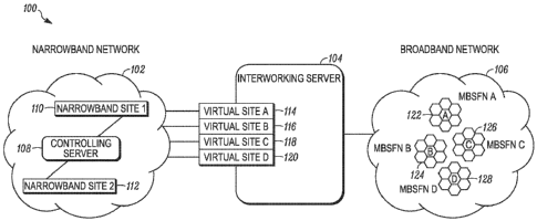
[026] Referring now to the drawings, and in particular FIG. 1, a communication
system implementing embodiments in accordance with the present teachings is
shown
and indicated generally at 100. System 100 comprises: a narrowband network 102
having a controlling server 108 and two narrowband sites 110 and 112; an
interworking server 104; and a broadband network 106, which in this example
implementation is a Multimedia Broadcast/Multicast Service (MBMS)-enabled
broadband network. Only a limited number of system elements 102, 104, 106,
108,
110, and 112 are shown for ease of illustration, but additional such elements
may be
included in the communication system 100. Moreover, other components needed
for
a commercial embodiment of the system 100 are omitted from the drawing for
clarity
in describing the disclosed embodiments.
[027] Generally speaking, pursuant to the present teachings, the interworking
server
104 is configured (i.e., adapted) to facilitate interoperability between the
narrowband
network 102 and the broadband network 106. For example, signaling between the
interworking server 104 and the controlling server 108 enables or facilitates
participation within a narrowband communication group by communication devices
coupled (i.e., operatively coupled or communicatively coupled) to the
broadband
network 106 and using broadband resources.
[028] As used herein, a "communication group" (also referred to herein simply
as a
"group") has a plurality of members that are authorized to engage in mutual
communication with each other while being joined to an active communication
session associated with the group. A communication group wherein voice media
is
6
CA 02870670 2014-10-15
WO 2013/158362
PCT/US2013/034889
communicated between the members is known as a talkgroup, but communication
groups can be created to communicate any type of media between its members. A
"narrowband communication group" is any communication group wherein
membership, participation and/or resources for the group are managed, at least
in part,
by one or more elements within a narrowband network, such as the controlling
server
108.
[029] Furthermore, a narrowband communication device (or "narrowband device")
is a communication device having the hardware, software and/or firmware needed
to
operatively couple to and communicate using a narrowband network. A broadband
communication device (or "broadband device") is a communication device having
the
hardware, software and/or firmware needed to operatively couple to and
communicate
using a broadband network. It is understood that both a narrowband device and
a
broadband device can share the same physical housing and operate as either a
narrowband device or a broadband device at any given point in time, as relates
to the
teachings herein.
[030] Moreover, as used herein, a communication device being operatively or
communicatively coupled (or simply coupled) to a broadband or narrowband
network
means that the communication device has exchanged the necessary signaling with
the
network to send or receive information or communications (e.g., media) using
the
network. For example, a broadband device in an idle state and receiving MBMS
point-to-multipoint transmissions is considered coupled to a broadband
network, as
well as a broadband device that has successfully exchanged signaling with the
broadband network using the Radio Resource Control (RRC) protocol specified in
3GPP TS 25.331.
[031] We now turn to a detailed description of the system elements within
communication system 100. In general, infrastructure elements within the
narrowband network 102 (including the controlling server 108 and
infrastructure
elements within the narrowband sites 110 and 112), the interworking server
104,
infrastructure elements within the broadband network 106, and the
communication
devices are all adapted or configured with hardware, software, and/or firmware
to
perform their particular functionality, including functionality in accordance
with
7
CA 02870670 2014-10-15
WO 2013/158362
PCT/US2013/034889
embodiments of the present disclosure, for example, as described in detail
below with
respect to the remaining figures. Being "adapted" or "configured" means that
such
elements are implemented using one or more (although not shown) memory
devices,
interfaces, and/or processing devices that are operatively coupled. The memory
devices, interfaces, and/or processing devices (also generally referred to
herein as a
computer), when programmed, form the means for these system elements and
communication devices to implement their desired functionality.
[032] Interfaces are used for exchanging signaling, also referred to herein as
messaging (e.g., messages, packets, datagrams, frames, superframes, and the
like),
containing control information, voice, or non-voice media between the elements
of
system 100. A particular interface of any system element or communication
device
might be wired or wireless depending on the other device(s) to which the
interface
connects. For example, the interworking server 104 may have both a wired
interface
to communicate with (i.e., communicatively connect or communicatively couple
to)
infrastructure elements within the narrowb and network 102 and a wireless
interface to
communicate with infrastructure elements within the broadband network 106.
Examples of wired interfaces include, but are not limited to, Ethernet, Ti,
USB
interfaces, etc.
[033] Where system elements or communication devices use wireless signaling,
the
interfaces comprise components including processing, modulating and
transceiver
components that are operable in accordance with any one or more standard or
proprietary wireless interfaces, supporting, for instance, LTE (Long Term
Evolution),
WiFi, etc. Some of the functionality of the processing, modulating and
transceiver
components may be performed by means of a processing device, through
programmed
logic such as software applications or firmware stored on the memory device of
the
system element, or through hardware.
[034] The processing devices utilized by the elements of system 100 and the
communication devices using system 100 may be partially implemented in
hardware
and, thereby, programmed with software or firmware logic or code for
performing
functionality described by reference to FIGs. 2-14; and/or the processing
devices may
be completely implemented in hardware, for example, as a state machine or ASIC
8
CA 02870670 2014-10-15
WO 2013/158362
PCT/US2013/034889
(application specific integrated circuit). The type of memory implemented can
include short-term and/or long-term memory to store information needed for the
functioning of the respective elements. The memory may further store software
and/or firmware for programming the processing device with the logic or code
needed
to perform its functionality.
[035] The narrowband network 102 can be a trunked or a combined trunked and
conventional network but is any type of network that assigns only "narrowband
channels" for communication devices to use in transmitting and/or receiving
(i.e.,
communicating) media. A narrowband channel is a channel or communication
resource used to send messages, wherein the bandwidth is sufficiently narrow
such
that only one media stream is transported on the channel at any given time. In
one
illustrative implementation, a narrowband channel has a bandwidth of 25 kHz or
less.
In a particular embodiment, the narrowband network 102 comprises, for example,
one
or more Project 25 or Terrestrial Trunked Radio (TETRA) Land Mobile Radio
(LMR)
communication systems.
[036] Within narrowband network 102, each narrowband site (e.g., 110 and 112)
comprises or has associated therewith a set of narrowband channels, which are
the
narrowband resources for the narrowband site. One or more of these narrowband
channels can be dedicated for sending control information (i.e., control
channels).
The controlling server 108 within the narrowband network 102 manages the
narrowband resources of the narrowband sites by assigning narrowband channels
to
facilitate communications between narrowband communication devices (e.g., used
by
group members) that are registered to the narrowband network 102 and located
at and
communicatively coupled to the sites.
[037] The broadband network 106 is any type of network that can assign
"broadband
channels" for communication devices to use in communicating media. By contrast
to
a narrowband channel, a broadband channel (also sometimes referred to in the
art as a
"wideband" channel) is a channel or communication resource used to send
messages,
wherein the bandwidth is sufficiently broad to enable multiple media streams
to share
a single broadband channel. In one illustrative implementation, a broadband
channel
9
CA 02870670 2014-10-15
WO 2013/158362
PCT/US2013/034889
has a bandwidth of greater than 1 MHz (supporting data rates of greater than
about 1.5
Mbits/s).
[038] As mentioned earlier, the broadband network 106 is an MBMS-enabled
communication network having infrastructure elements that are configured to
provide
MBMS service as specified in multiple 3rd Generation Partnership Project
(3GPP)
Technical Specifications (TSs), e.g., 3GPP TS 22.246 and 26.346. However,
broadband network 106 can be any point-to-point and/or point-to-multipoint
enabled
communication network, including a network that uses unicast transports,
multicast
transports, broadcast transports, or any combination thereof. Moreover, the
teachings
herein are applicable to any broadband network having a core network and a
Radio
Access Network (RAN) that is adapted to be interoperably coupled to a
narrowband
network as taught herein. For example, the present teachings are also
applicable to a
communication system 100 having a Long Term Evolution (LTE) broadband network
(where at least some of its elements are configured to operate in conformity
with one
or more aspects of 3GPP LTE TSs), a 3GPP2 network, or a Worldwide
Interoperability for Microwave Access (WiMAX) network, for example.
[039] Shown within the broadband network 106 are multiple broadband areas,
which
in this case are four Multimedia Broadcast over a Single Frequency Network
(MBSFN) areas 122 (A), 124 (B), 126 (C) and 128 (D). A broadband area, as used
herein, represents a geographic region within the entire broadband network.
Although
the example implementation described herein bases the geographical
partitioning of
the broadband areas (e.g., the MBSFN areas) on synchronized point-to-
multipoint
transmissions, the partitioning for broadband areas, in general, is not so
limited. As
described in the 3GPP TSs, a RAN, such as an LTE Evolved Universal Mobile
Telecommunications System Terrestrial Radio Access Network (E-UTRAN), can be
partitioned into one or more MBSFN areas, identified by MBSFN area IDs, with
each
MBSFN area covering a particular geographical region in which a synchronized
MBMS transmission can occur. MBMS transmissions are synchronized across
eNodeBs within each MBSFN so that all MBMS-capable broadband devices within a
given MBSFN's coverage area can receive the identical transmission.
CA 02870670 2014-10-15
WO 2013/158362
PCT/US2013/034889
[040] Each MBSFN area of FIG. 1 includes a plurality of cells, identified by
cell
identifiers, which define its coverage area. Moreover, each MBSFN area is
shown as
a collection of seven hexagons, with each hexagon representing one or more
(typically three) cells of an eNodeB that can participate in the synchronized
point-to-
multipoint transmissions for the MBSFN area. While the overall shape of each
MBSFN area within FIG. 1 is uniform and non-overlapping, this is only
illustrative
and does not limit an actual MBSFN area implementation. In practice, MBSFN
areas,
which can comprise any number of cells, may (and typically do) differ in size
and/or
shape; and one or more such areas may overlap in coverage area, in a practical
implementation. It should be noted that the present teachings are also
applicable
where the broadband network 106 does not provide MBMS services, as explained
in
detail below.
[041] The interworking server 104 manages (e.g., has provisioned thereon) one
or
more virtual narrowband sites (also referred to herein as virtual sites). In
the example
implementation shown in FIG. 1, the interworking server 104 manages four
virtual
sites 114-120 but may be provisioned with more or fewer such sites. A virtual
narrowband site is defined herein as a logical grouping of data (e.g., a site
ID, a
plurality of channel IDs and/or channel frequencies, etc.) maintained by an
interworking server and presented to a controlling server as an actual
physical
narrowband site. As such, each virtual narrowband site has associated
therewith a
plurality of virtual narrowband channels, again presented to the controlling
server 104
as actual narrowband channels, which the controlling server 104 is allowed to
manage
in accordance with the present teachings. The virtual narrowband channels are,
for
instance, identified using channel identifiers and/or channel frequencies that
are
compatible with those used in a narrowband network to identify actual
narrowband
channels.
[042] In one example implementation, MBSFN areas 122-128 within the broadband
network 106 are associated with (i.e., mapped to) corresponding virtual
narrowband
sites 114-120 provisioned on the interworking server 104. As shown, each MBSFN
area 122-128 corresponds to exactly one virtual narrowband site, as indicated
by the
letter designations "A" through "D." Moreover, in one particular embodiment,
each
11
CA 02870670 2014-10-15
WO 2013/158362
PCT/US2013/034889
virtual site has mapped thereto a plurality of pre-allocated MBMS bearers from
the
corresponding MBSFN area, which serve as the plurality of virtual narrowband
channels for the virtual site.
[043] For example, virtual narrowband site A is mapped to MBSFN area A,
wherein
virtual narrowband site A comprises a plurality of virtual narrowband channels
mapped to a plurality of MBMS bearers that are pre-allocated from MBSFN area
A.
Alternate embodiments, however, allow for the mapping of multiple MBSFN areas
to
the same virtual narrowband site, or the mapping of a single MBSFN area to
multiple
virtual narrowband sites, as indicated below with respect to FIG. 11.
Moreover,
virtual narrowband sites need not be mapped to MBSFN areas, and in other
example
implementations, can be mapped to broad geographical areas, tracking areas, or
specific sets of broadband devices, such as those without access to MBMS
service.
[044] This "mapping" can be simply a matrix or a table stored on the
interworking
server 104 associating each narrowband site with a corresponding broadband
area and
(in some embodiments) identifying a plurality of broadband resources that are
pre-
allocated from the broadband area. In the example implementation mentioned
above,
a plurality of pre-allocated point-to-multipoint (e.g., MBMS) bearers is
mapped to the
plurality of virtual narrowband channels for a virtual site. "Pre-allocated,"
as used
herein, means that the bearer for a virtual site is established a priori and
held in
reserve until needed for an active communication session involving a broadband
device associated with the virtual site. Such an implementation utilizing pre-
allocated
broadband resources mapped to virtual narrowband channels allows the
controlling
server 108 to directly manage broadband resources for an active communication
session by managing the virtual narrowband channels of a given virtual site.
In
another example implementation, pre-allocated point-to-point resources are
mapped
to one or more of the virtual narrowband channels to allow the controlling
server 108
to directly manage the broadband resources for an active communication
session.
[045] However, in yet another example implementation, upon selection by the
controlling server 108 of a virtual narrowband channel, one or more point-to-
point
bearers and/or or point-to-multipoint bearers are dynamically allocated (i.e.,
established for use by one or more broadband devices) "on-the-fly" or as
needed for a
12
CA 02870670 2014-10-15
WO 2013/158362
PCT/US2013/034889
communication session. This alternative implementation allows the controlling
server
108 to indirectly manage broadband resources by triggering the interworking
server
104 to dynamically establish the broadband resources as needed. Accordingly,
embodiments herein support the use of pre-allocated point-to-point broadband
resources, dynamically established point-to-point broadband resources, pre-
allocated
point-to-multipoint broadband resources, dynamically established point-to-
multipoint
broadband resources, or any combination thereof, mapped to virtual narrowband
channels.
[046] We turn now to a detailed description of the functionality of the system
100
elements in accordance with the teachings herein and by reference to the
remaining
figures. FIG. 2 shows a logical flowchart 200 illustrating general
functionality of the
interworking server 104 in accordance with an embodiment of the present
disclosure.
At 202, an interworking server (e.g., 104) maintains at least one virtual
narrowband
site, each comprising a plurality of virtual narrowband channels known by a
controlling server (e.g., 108). In an embodiment, the controlling server 108
"knows"
the virtual narrowband channels for each virtual narrowband site by being
provisioned
or programmed with such data (e.g., channel IDs and/or frequencies) that
represents
the virtual narrowband channels. This provisioning is performed by a
narrowband
system administrator, the interworking server 104, etc. In accordance with the
present
teachings, each virtual narrowband channel, when assigned by the controlling
server
108, represents a corresponding set of broadband resources allocated within
the
broadband network 106, as explained in more detail below.
[047] Further in accordance with 202, a first broadband device (operatively)
coupled
to the broadband network 106 is associated with a first virtual narrowband
site (of the
at least one virtual narrowband sites managed by the interworking server 104).
As
such, a broadband device may be associated with a given virtual narrowband
site a
priori. However, in accordance with embodiments of the present disclosure, the
interworking server 104 associates (i.e., stores an association or mapping of)
a given
broadband device with a given virtual narrowband site depending on one or more
factors. These factors include, but are not limited to: whether the broadband
network
and the broadband device are point-to-multipoint-enabled (e.g., MBMS-enabled);
the
13
CA 02870670 2014-10-15
WO 2013/158362
PCT/US2013/034889
location of the broadband device within the broadband network (e.g., with
respect to
FIG. 4, a broadband device is associated (upon sending a service activation
request)
with a virtual site mapped to the MBSFN area in which the broadband device is
located); the location of the broadband device within the broadband network
106
relative to other broadband devices participating in a same narrowband
communication group; the number of narrowband communication groups associated
with a particular virtual narrowband site, etc. Moreover, the interworking
server 104
may appropriately change the association of a broadband device from one
virtual site
to a different virtual site, for example, in accordance with embodiments
described
herein by reference to FIGs. 5 and 13.
[048] At 204, the interworking server 104 exchanges signaling with the
controlling
server 108 to enable communications by the first broadband device using a
first set of
broadband resources corresponding to a first virtual narrowband channel of the
first
virtual narrowband site. The first virtual narrowband channel is assigned by
the
controlling server 108 for use by a first virtual narrowband device which
represents
(i.e., symbolizes) the first broadband device. More particularly, in
accordance with
the teachings herein, a broadband device coupled to the broadband network 106
is
represented by a virtual narrowband device when data identifying a virtual
narrowband device is associated with one or more corresponding broadband
device
identifiers in a relationship or mapping stored on the interworking server
104.
[049] In one example implementation, the first virtual narrowband device
represents
the first broadband device using a narrowband device identifier, which is
compatible
with IDs used in the narrowband network to identify actual narrowband devices.
The
mapping between a narrowband device identifier and a broadband device
identifier
may by one-to-one. However, in an alternative implementation, multiple
broadband
device identifiers are mapped to a single narrowband device identifier. A
narrowband
device identifier comprises, for example, a P25-compatible subscriber unit
identifier
(SUID), a unit identifier, or some other form or combination of such
identifiers.
[050] In accordance with embodiments of the teachings herein (e.g., by
reference to
FIGs. 2-14), signaling between the interworking server 104 and the controlling
server
108 contains at least one narrowband device identifier for a virtual
narrowband device
14
CA 02870670 2014-10-15
WO 2013/158362
PCT/US2013/034889
that represents a corresponding broadband device coupled to the broadband
network
106. Whereas, signaling between the interworking server 104 and the broadband
network 106 or a broadband device coupled to the broadband network 106
contains a
broadband device identifier for the broadband device.
[051] In one embodiment, the interworking server 104 (e.g., using an internal
conversion element 308 (FIG. 3)) performs broadband-to-narrowband device
identifier conversion, or vice versa, depending on the direction of the
signaling. Such
a conversion includes, for example, a simple reformatting between a narrowband
network supported device identifier format and a broadband network supported
device
identifier format. Alternatively, the broadband device is identified within
the
broadband network 106 using a narrowband device identifier (i.e., the
broadband
device identifier is the same as the narrowband device identifier). In such a
case, the
"conversion" is simply forwarding the device identifier within the messages.
[052] Similarly, the interworking server 104 (e.g., using an internal
conversion
element 308 (FIG. 3)) may perform a conversion (e.g., reformatting, etc.)
between a
broadband group identifier and a corresponding narrowband group identifier
(and vice
versa), when the messaging received by and sent from the interworking server
104
necessitates the inclusion of a communication group identifier (e.g.,
messaging of FIG.
6). Alternatively, the broadband group identifier and the corresponding
narrowband
group identifier are the same, and the "conversion" simply comprises
forwarding the
group identifier within the messages.
[053] Moreover, in accordance with the teachings herein, the controlling
server 108
is provisioned, e.g., a priori, with at least the IDs for one or more virtual
narrowband
devices and the IDs for a plurality of virtual narrowband channels for one or
more
virtual narrowband sites. Thus, during operation, the interworking server 104
provides to the controlling server 108: the ID for a given virtual narrowband
device
and the virtual narrowband site where the virtual narrowband device is located
(which
is the virtual narrowband site to which the corresponding broadband device is
associated). Using this information, the controlling server 108 manages what
it
perceives to be narrowband channels for use in an active communication session
(i.e.,
a call), by narrowband devices at the particular narrowband sites. In managing
the
CA 02870670 2014-10-15
WO 2013/158362
PCT/US2013/034889
virtual narrowband channels, the controlling server 108 effectively manages
(directly
and/or indirectly via the interworking server 104) broadband resources for use
by
broadband devices coupled to the broadband network 106.
[054] In a particular example, the interworking server 104 provides to the
controlling server 108 (e.g., during unit or location registration procedures
as
described below with reference to FIG. 4 and FIG. 5 respectively) an ID for
the first
virtual narrowband device, and identifies (e.g., using a site ID) the first
virtual
narrowband site, within which the first virtual narrowband device is
purportedly
"located." Upon receiving notification that the virtual narrowband device is
ready to
communicate (e.g., during initiation of group communication for a narrowband
group
that the virtual narrowband device has joined or floor request procedures for
the
virtual narrowband device), the controlling server 108 selects a first virtual
narrowband channel (of the plurality of virtual narrowband channels) of the
first
virtual narrowband site, for use by the first virtual narrowband device.
[055] Thereafter, exchanging signaling (204) comprises the interworking server
104:
receiving from the controlling server 108 an indication of the assignment of
the first
virtual narrowband channel; and determining the first set of broadband
resources
corresponding to the selected first virtual narrowband channel. In an
embodiment, the
indication of the assignment of the first virtual narrowband channel is
received in a
narrowband call grant message, which in one embodiment conforms to a format
described in the P25 standards.
[056] Where the broadband network 106 and the first broadband device are point-
to-
multipoint-enabled, determining the first set of broadband resources comprises
selecting a first point-to-multipoint bearer. In one implementation, the point-
to-point
bearer is pre-allocated and mapped to the first virtual narrowband channel.
Alternatively, the interworking server 104 communicates with the broadband
network
106 to dynamically obtain the point-to-multipoint bearer and then maps the
bearer to
the first virtual narrowband channel.
[057] In one example implementation, when the broadband network 106 and the
first
broadband device are MBMS-enabled, the first point-to-multipoint bearer
comprises a
MBMS bearer of a plurality of MBMS bearers pre-allocated from a first MBSFN
area
16
CA 02870670 2014-10-15
WO 2013/158362
PCT/US2013/034889
of the broadcast network, wherein the plurality of MBMS bearers is mapped to
the
plurality of virtual narrowband channels for the first virtual narrowband
site.
Alternatively, the MBMS bearers are not pre-allocated.
[058] Where the broadband network 106 or the first broadband device is not
point-
to-multipoint enabled, determining the first set of broadband resources can
comprise
the interworking server 104 signaling the broadband network 106 to allocate
(i.e.
obtain) a point-to-point bearer (as described below by reference to FIG. 7,
and which
may include procedures that conform to the LTE TSs), and mapping the obtained
(or
allocated) point-to-point bearer to the first virtual narrowband channel.
Where
multiple point-to-point bearers are needed for multiple broadband devices
belonging
to the same virtual narrowband site, they may all be mapped to the same
virtual
narrowband channel once obtained. As mentioned above, pre-allocated point-to-
point
bearers can also be used. In such a case, the interworking server 104
determining the
first set of broadband resources comprises selecting the point-to-point bearer
that is
already mapped to the first virtual narrowband channel.
[059] During communications, the interworking server 104 receives a first
media
stream and converts the first media stream to a second media stream for
distribution to
a communication group comprising at least the first virtual narrowband device.
Reception, conversion and distribution of media streams occurs in multiple
directions.
For example, receiving the first media stream from the narrowband network 102,
converting the first media stream to a second media stream which is compatible
with
the broadband network 106, and sending the second media stream to the first
broadband device represents the flow of media from the narrowband network 102
(e.g., from a narrowband device) to a broadband device.
[060] Receiving the first media stream from the first broadband device,
converting
the first media stream to the second media stream, which is compatible with
the
narrowband network 102, and sending the second media stream to the narrowband
network 102 for distribution represents the flow of media from a broadband
device to
the narrowband network 102 (e.g., to one or more narrowband devices coupled
the
narrowband network 102). In an embodiment consistent with these teachings, a
17
CA 02870670 2014-10-15
WO 2013/158362
PCT/US2013/034889
media stream received from the first broadband device may also be sent to
other
broadband devices coupled to the broadband network 106.
[061] FIG. 3 is a block diagram of a communication system 300 that illustrates
the
passing and conversion of signaling between the broadband network 106 and the
narrowband network 102 consistent with an embodiment of the present teachings.
The elements shown for system 300 include: the interworking server 104, the
controlling server 108 and the narrowband site 110 of the narrowband network
102, a
narrowband device 314 coupled to the narrowband network 102, the broadband
network 106, and a broadband device 312 coupled to the broadband network 106.
Narrowband and broadband devices comprise devices commonly referred to in the
art
as mobile devices, access devices, access terminals, mobile stations, mobile
subscriber units, subscriber units, user devices, client devices, and the
like, which can
be any type of communication devices, such as radios, mobile phones, mobile
data
terminals, Personal Digital Assistants (PDAs), laptops, two-way radios, cell
phones,
etc.
[062] More particularly, FIG. 3 shows the interworking server 104 comprising a
call
control element 302, a floor arbiter element 304, a media manager element 306,
and a
conversion element 308; the first three elements also referred to herein as
"call
control," "floor arbiter," and "media manager," respectively. These elements,
and the
internal messaging that takes place between them, support some of the
functionality
of the interworking server 104 described herein. The call control element 302,
for
example, processes requests received from the broadband network 106, generates
internal messages for the conversion element 308, determines which sites
communication groups are associated with, and validates successful completion
of
registrations.
[063] Functionality performed by the floor arbiter 304 includes, but is not
limited to:
receiving and handling floor requests from broadband devices; generating
internal
messages for the conversion element 308; determining sites associated with a
communication group; obtaining broadband resources or instructing call control
302
to do so; informing the media manager 306 of the obtained broadband resources;
and
starting and stopping media distribution. The media manager 306 receives media
18
CA 02870670 2014-10-15
WO 2013/158362
PCT/US2013/034889
from a communication device holding the floor during a communication session
(which can include a console device during a console takeover) and distributes
the
media to the other communication devices participating in that session. The
participating devices may include both narrowband and broadband devices or
only
broadband devices participating in a narrowband communication group. In a
particular embodiment where a console device has taken over the floor, the
media
manager 306 continues to receive media from the communication device that has
lost
the floor to the console. The media manager 306 sends that media to the
narrowband
network 102 while media from the console is distributed to the communication
devices participating in the communication session.
[064] A communication device holding the floor sends out media as a media
stream.
As used herein, a "media stream" can have both a media and a control
component.
For example, a media stream can comprise media packets that conform to a
specific
protocol and contain video or voice data while also comprising control
signaling that
is not part of the media proper. The media stream, however, does not have to
be
multiplexed in this way and may contain only media. The term "media packets"
refers to media within the media stream that has been discretized into finite
data units
for transmission or storage, from which the media may be reconstructed through
the
use of a decoder.
[065] For a media stream received at the conversion element 308 from a
narrowband
device 314 located at and coupled to the narrowband site 110, one of the
functions of
the conversion element 308 is to de-multiplex the signals within the stream.
Signaling
within the media stream might be intended for the call control 302 or floor
arbiter 304
elements while the media itself is meant for communication devices. The
conversion
element 308 separates the media from the control signals and generates a new
media
stream that is sent to the media manager 306 for distribution (e.g., FIG. 9 at
906 and
912). Generation of the new media stream could also involve reformatting or
transcoding the media packets to make it suitable for broadband distribution.
The
conversion element 308 also generates separate control signals and sends each
to its
proper destination (e.g., FIG. 9 at 906-910).
19
CA 02870670 2014-10-15
WO 2013/158362
PCT/US2013/034889
[066] Alternatively, the conversion element 308 might multiplex or combine
additional control information with media to generate a media stream. For
example,
the conversion element 308 might add control signaling to a broadband media
stream
received from a broadband device 312 via the media manager 306 before
generating a
corresponding narrowband media stream and sending it to the appropriate
narrowband
site 110 (e.g., FIG. 8 at 802-806). By contrast, the broadband media stream
sent to
the other broadband devices does not contain the added control signaling
(e.g., FIG. 8
at 802,808-812). In this way, control signaling can be included within or
removed
from media streams being sent in either direction, i.e., from the narrowband
to the
broadband network, and vice versa.
[067] The conversion element 308 performs additional functionality in that it
"converts" messages, meaning that it generates messages that are compatible
with
their intended destinations. For example, the interworking server 104
"converting" a
message comprises the interworking server 104 generating a second message in
response to a first message that it receives. This includes formatting
generated
messages and adhering to the protocols that are observed by the multiple
elements
that comprise communication system 300 as a whole. Several differing protocols
and
formats may be used for the aforementioned communication system, as indicated
below. Thus, the conversion may or may not involve converting a format of the
first
message to a different format to generate the second message.
[068] It is also consistent with an embodiment of the present teachings that a
message "generated" by the conversion element 308 is identical to the message
it
received. In other words, the conversion element 308 may "convert" a message
simply by forwarding the message without making any change to the content or
format of that message. The message sequence diagrams shown in FIGs. 4-10
illustrate the interworking server 104 "converting" messages being sent
between the
broadband network or broadband devices and the narrowband network or
narrowband
devices.
[069] As a further illustrative example, the conversion element 308 within the
interworking server 104 receives a single combined call/floor control message
from
the controlling server 108. The call control signaling is then split off from
the
CA 02870670 2014-10-15
WO 2013/158362
PCT/US2013/034889
received transmission, and two messages are generated, one for call control
302, and
one for floor control 304, each being compatible with the broadband network
106. In
the opposite direction, call control and floor control signals from the
broadband
network 106 might be combined by the conversion element 308 into a single
call/floor
control message that is suitable for the controlling server 108. In an
alternate
embodiment, the narrowband network 102 sends separate call control and floor
control messages to the interworking server 104 using different interfaces.
[070] FIGs. 4-10 provide further examples of the interworking server 104
exchanging signaling (204) with the controlling server 108 within the
narrowband
network 102 to enable communications by one or more broadband devices, such as
the one shown at 312 (e.g., the first broadband device), which are operatively
coupled
to the broadband network 106. The signaling indicated in FIGs. 4-10 can
comprise a
variety of protocols, which might include, for example, a suitable proprietary
or
standard session management protocol, such as Session Initiation Protocol
(SIP) as
defined in Internet Engineering Task Force (IETF) Request for Comments (RFC)
3261 dated June 2022.
[071] For example, the interworking server 104 might exchange various standard
SIP messages with the broadband network 106 and/or broadband devices to
facilitate
the present teachings as described herein. The SIP messages include, but are
not
limited to a SIP INVITE, a SIP MESSAGE, a SIP PUBLISH, a SIP NOTIFY, a SIP
SUBSCRIBE, a SIP REGISTER, a SIP ACK, a SIP OPTIONS, a SIP PRACK, a SIP
REFER, a SIP UPDATE, a SIP INFO, a SIP BYE, a SIP CANCEL, etc. As an
illustrative example, the broadband group association request 602 referenced
in FIG.
6 may be sent using a SIP INVITE, a SIP MESSAGE, or a SIP PUBLISH message.
Similarly, the interworking server 104 might exchange signaling with the
narrowband
network 102 without any modification to the signaling that the controlling
server 108
processes with respect to actual narrowband devices and narrowband sites. This
obviates the need to modify elements within the narrowband network 102 or the
narrowband devices.
[072] Additional examples of control signaling protocols that may be used
include:
Serial Line Internet Protocol (SLIP), as defined in IETF RFC 1055 dated June
1988;
21
CA 02870670 2014-10-15
WO 2013/158362
PCT/US2013/034889
Point-to-Point Protocol (PPP), as defined in IETF RFC 1968 dated June 1996;
Binary
Floor Control Protocol (BFCP), as defined in IETF RFC 4582 dated November
2006;
or some variations thereof Talk Burst Control Protocol (TBCP), Media Burst
Control Protocol (MBCP), or any other protocol compatible with the Open Mobile
Alliance (OMA) suite of standards for Push-to-talk over Cellular (PoC) are
also a
viable option.
[073] Signaling involving media transport might involve a proprietary protocol
or a
standardized protocol, such as Real-time Transport Protocol (RTP), as defined
in
IETF RFC 3550 dated July 2003, or User Datagram Protocol (UDP), as defined by
IETF RFC 786 dated August 1980, for example. In an embodiment, signaling
internal
to the interworking server 104 comprises proprietary signaling, but is not
necessarily
limited as such. The preceding list is not exhaustive, and additional
protocols,
standard or proprietary, may be used in differing combinations for signaling
to and
from the interworking server 104 from the broadband and narrowband networks
and
communication devices coupled to those networks.
[074] For example, in accordance with a message sequence diagram 400
illustrated
in FIG. 4, exchanging signaling comprises: receiving a service activation
request for
the first broadband device (e.g., 312); converting the service activation
request to a
narrowband device registration message; and sending the narrowband device
registration message to the controlling server 108 to indicate a request for
registration
of the first virtual narrowband device to the narrowband network 102. In FIG.
4,
signaling is exchanged between the broadband device 312, the interworking
server
104 elements and the controlling server 108.
[075] The term "unit registration," as used herein, refers to a process by
which a
narrowband communication device becomes associated with (i.e., registered to)
a
particular narrowband network to which the narrowband device is coupled (via a
particular narrowband site). Thus, unit registration (as illustrated by FIG.
4) registers
a narrowband device to a narrowband network. "Location registration" (as
illustrated
by FIG. 5) identifies the narrowband site to which the narrowband device is
coupled
or, in other words, identifies the narrowband site where the narrowband device
is
located.
22
CA 02870670 2014-10-15
WO 2013/158362
PCT/US2013/034889
[076] In accordance with the present teachings, narrowband unit and location
registration processes are applied to register a virtual narrowband device to
a
narrowband network and to associate the virtual narrowband device with
particular
virtual narrowband site. In one embodiment, P25 unit registration and location
registration procedures are implemented, including the signaling that is used
in the
case of actual narrowband networks, sites, and devices. However, any
narrowband
unit and location registration procedures could be used.
[077] In particular, FIG. 4 shows the broadband device 312 sending a service
activation request 402 to the call control element 302. Such a service
activation
request might be sent automatically when the broadband device 312 is powered
up
and registered with the broadband network 106, using any suitable broadband
registration process, or sent at a later time, perhaps in response to user
input entered
into the broadband device 312. Included with the service activation request
402 may
be particular service settings that define certain parameters regarding
service for the
broadband device 312. The call control element 302 receives the service
activation
request 402, records the particular service settings, and responds by sending
an
optional acknowledgement 404 back to the originating broadband device 312.
Alternatively, call control 302 can send the optional acknowledgement 404
after
receiving a device registration response 412.
[078] After receiving the service activation request 402, the call control
element 302
determines whether a narrowband (e.g., P25) unit registration procedure should
be
performed for the broadband device 312, e.g., by determining whether there is
a
corresponding narrowband device identifier mapped to the broadband device 312.
If
the narrowband unit registration procedure should be performed, call control
302
generates and sends an internal device registration request 406 to the
conversion
element 308. The conversion element responsively generates a narrowband device
registration request 408, which it sends to the controlling server 108.
[079] The resulting request 408 includes the narrowband device identifier that
uniquely identifies a virtual narrowband device to the controlling server 108,
wherein
the narrowband device identifier represents the broadband device 312. In an
embodiment, as a result of the service activation procedure, the interworking
server
23
CA 02870670 2014-10-15
WO 2013/158362
PCT/US2013/034889
104 determines and maps a virtual narrowband site to the broadband device 312.
Upon receipt of the narrowband registration request 408, the controlling
server 108
processes the request 408, as it would such a request for an actual narrowband
device,
and sends a narrowband device registration response 410 back to the conversion
element 308. The conversion element 308, in turn, generates and transmits an
internal
device registration response 412 back to the call control element 302.
[080] In a particular embodiment, the broadband device 312 might withdraw from
service upon powering down, or in response to user input. The broadband device
312,
for example, might send a deactivation request (not shown) containing a
broadband
device identifier to call control 302, which then passes an internal message
to the
conversion element 308. The conversion element 308 then generates a device
deregistration message and sends it to the controlling server 108 for
processing in
accordance with appropriate standard or proprietary protocols. The controlling
server
108 then sends a narrowband device deregistration response back to the
conversion
element 308, which, in turn, generates an internal device deregistration
response and
sends it back to the call control element 302.
[081] Turning now to FIG. 5, illustrated therein is a message sequence diagram
500
showing signaling between the broadband device 312, the interworking server
104
and the controlling server 108 used to perform a broadband area location
update and
corresponding narrowband (e.g., P25) location registration, in accordance with
an
embodiment of the present teachings. For example, where a first virtual
narrowband
site (e.g., to which broadband device 312 is associated) is mapped to a first
broadband
area, exchanging signaling (204) between the interworking server 104 and the
controlling server 108 comprises the interworking server 104: receiving an
indication
that a first broadband device 312 has moved to a second broadband area that is
mapped to a second virtual narrowband site; changing the association of the
first
broadband device 312 from the first virtual narrowband site to the second
virtual
narrowband site; and sending a narrowband location registration message to the
controlling server 108 indicating that the first virtual narrowband device has
changed
location (i.e., has "moved" or changed location) from the first virtual
narrowband site
to the second virtual narrowband site.
24
CA 02870670 2014-10-15
WO 2013/158362
PCT/US2013/034889
[082] In a particular embodiment consistent with illustrative system 100, the
first
broadband area comprises a first MBSFN area of the broadband network, and the
second broadband area comprises a second MBSFN area of the broadband network.
Moreover, the "movement" or change/indication of "location" of the virtual
narrowband device is a logical movement or location affected within the
interworking
server 104 but is perceived by the controlling server 108 as a movement of an
actual
narrowband device between actual narrowband sites.
[083] An event, that causes the interworking server 104 to update the
controlling
server 108 with the virtual narrowband site to which a particular broadband
device/virtual narrowband device pair is associated is referred to herein as a
mobility
event. In one implementation scenario, the mobility event comprises a
broadband
device moving from one broadband area (e.g., MBSFN C 126) to another broadband
area (e.g., MBSFN B 124), thereby resulting in the association of the
broadband
device and corresponding virtual narrowband device changing from a first
virtual site
(e.g., C 118) to a different virtual site (e.g., B 116). Alternatively, the
mobility event
comprises the broadband device 312 powering up and registering with the
broadband
system. In a corresponding embodiment, an initial location registration for
the
broadband device 312 is done concurrently with the device registration when
the unit
powers up, using combined signaling (e.g., adding broadband area and/or
virtual
narrowband site information to at least some of the signaling shown in FIG.
4).
Alternatively, the initial location registration takes place separately from
device
registration, and signaling is exchanged separately for each process.
[084] More particularly, with respect to FIG 5, upon the occurrence of a
mobility
event for the broadband device 312, it sends a broadband area location update
502
that is received by the call control element 302. The broadband area location
update
502 includes a broadband area ID (e.g., an MBSFN ID) that indicates the
current
position of the broadband device 312 with respect to the MBSFN areas that
comprise
the broadband network 106. The call control element 302 stores information
included
in the broadband area location update 502, and in so doing, records the
association of
the broadband device 312 with the identified MBSFN area. The interworking
server
104 also passes an internal location registration message 504 from the call
control
CA 02870670 2014-10-15
WO 2013/158362
PCT/US2013/034889
element 302 to the conversion element 308 with the MBSFN ID from message 502
and with the broadband device 312 ID.
[085] The conversion element 308 determines the virtual narrowband site to
which
the broadband device 312 is associated (in this case the virtual narrowband
site
mapped to the MBSFN ID) and determines the corresponding virtual narrowband
device ID for broadband device 312. Conversion element 308 then generates a
narrowband location registration message 506 having the determined virtual
narrowband device ID and also indicating the determined virtual narrowband
site to
which the identified virtual narrowband device is currently associated.
Conversion
element 308 sends the narrowband location registration message 506 (also
referred to
as a mobility message) to the controlling server 108 to process.
[086] While processing the mobility message 506, the controlling server 108
optionally sends a narrowband location registration acknowledgment (ACK) 508
that
is received at the conversion element 308, as a notification that the
controlling server
108 is processing mobility message 506. Responsive to ACK 508, conversion
element 308 generates and passes a location registration acknowledgement 510
with
the broadband device 312 ID to the call control element 302 as an internal
message.
ACKs 508 and 510 operate to suspend mobility message retry timers.
[087] When the narrowband location registration message 506 processing is
complete, the virtual narrowband device (corresponding to the broadband device
312)
is associated, by the controlling server 108, to the virtual site that is
mapped to the
MBSFN ID identified in the message 502. If the location registration process
is being
performed concurrently with unit registration, then the location registration
procedure
provides the initial indication of the virtual site where the virtual
narrowband device
is located. Alternatively, if the virtual narrowband device was previously
successfully
registered to the narrowband network 102, then its virtual site location is
updated.
[088] In addition, the controlling server 108 sends a narrowband location
registration reply 512 for the virtual narrowband device that is received at
the
conversion element 308. Upon receiving the reply 512, the conversion element
308
generates an internal location registration reply 514 identifying the
broadband device
312, which is forwarded to the call control element 302. In turn, the call
control
26
CA 02870670 2014-10-15
WO 2013/158362
PCT/US2013/034889
element 302 may send an optional acknowledgement 516 to the broadband device
312
signaling that its location update is completed.
[089] Shown in FIG. 6 is a message sequence diagram 600 that illustrates the
exchange of signaling between the broadband device 312, the interworking
server 104
and the controlling server 108 to enable the broadband device 312 to
participate in a
session or call for a particular narrowband communication group, in accordance
with
an embodiment of the present disclosure. In accordance with FIG. 6, exchanging
signaling (204) between the interworking server 104 and the controlling server
108
comprises the interworking server 104: receiving a broadband group association
request, for the first broadband device, which identifies a first narrowband
communication group; converting the broadband group association request to a
narrowband group affiliation request; and sending the narrowband group
affiliation
request to the controlling server 108 for joining the first virtual narrowband
device to
the first narrowband communication group.
[090] In general, when the user of the broadband device 312 wishes to
participate in
a communication session involving a particular narrowband communication group
managed by the narrowband network 102, he uses his broadband device 312 to
trigger,
with the controlling server 108, a narrowband affiliation procedure (e.g., a
P25
conforming procedure) to affiliate (also referred to herein as "join") the
corresponding
virtual narrowband device to the narrowband group. As a result, the
controlling
server 108 signals the virtual narrowband device (and the interworking server
signals
the broadband device 312) when the narrowband group is active; and the
controlling
server 108 properly routes media for the narrowband group to the interworking
server
104, which is forwarded to the broadband device 312.
[091] With greater particularity, FIG. 6 shows the broadband device 312
sending a
broadband group association request 602 that is received at the call control
element
302. The request 602 contains a broadband and/or narrowband identifiers for
the
broadband device 312 and the communication group for which session
participation is
desired. Upon determining that the identified communication group is among
those
managed by the narrowband network 102, call control 302 passes an internal
group
affiliation request 604 to the conversion element 308, which identifies the
27
CA 02870670 2014-10-15
WO 2013/158362
PCT/US2013/034889
communication group. Request 604 triggers the conversion element 308 to
generate a
narrowband group affiliation request 606 that identifies the virtual
narrowband device
(corresponding to the broadband device 312) and contains the ID for the
narrowband
communication group. If needed, prior to generating the request 606, the
conversion
element 308 performs a broadband to narrowband group identifier conversion to
obtain the narrowband group ID, which is inserted into the request 606.
Conversion
element 308 sends the request 606 to the controlling server 108.
[092] The controlling server 108 processes the request 606 to join the virtual
narrowband device to the identified narrowband group (as it would for such a
request
received from an actual narrowband device), which effectively joins the
broadband
device 312 to the identified narrowband group. Joining, as used herein, is the
process
by which the controlling server 108 and/or the interworking server 104
associates (or
affiliates, in the case of a talkgroup) a uniquely identified communication
device with
a uniquely identified communication group so that the communication device is
authorized to participate in an active communication session or call involving
the
communication group.
[093] Upon completing the processing for request 606, the controlling server
108
transmits a narrowband group affiliation response 608 identifying the virtual
narrowband device mapped to the broadband device 312 and identifying the
narrowband communication group, which is received at the conversion element
308.
Responsively, the conversion element 308 generates and sends to call control
302 an
internal group affiliation response 610, which identifies the broadband device
312 and
the narrowband communication group. Upon receiving the response 610, call
control
302 sends an acknowledgement 612 to the broadband device 312 signaling that it
is
successfully joined to the identified narrowband group in order to receive
active
communications for that group.
[094] In a further embodiment, the broadband device 312 de-associates with the
narrowband communication group. For example, message 602 is modified to become
a broadband group de-association request, to indicate that the broadband
device 312 is
de-associating from the narrowband communication group, so as to no longer
receive
media for that group. In turn, messages 604 to 610 are modified to facilitate
a
28
CA 02870670 2014-10-15
WO 2013/158362
PCT/US2013/034889
narrowband de-affiliation process to de-affiliate the corresponding virtual
narrowband
device from the narrowband group. In one example implementation, such de-
affiliation is accomplished by the controlling server 108 affiliating the
virtual
narrowband device with a "null" narrowband group, which simply serves as an
indication that the particular virtual narrowband device is not affiliated
with any
narrowband group. Acknowledgement 612 can also be modified to indicate to the
broadband device 312 the completion of the de-association procedure.
[095] FIG. 7 is a message sequence diagram 700 illustrating a group
communication
session for a narrowband communication group being initiated by a broadband
device
A 702 in accordance with an embodiment of the present disclosure. The
signaling
shown in diagram 700 includes signaling between the interworking server 104
and
broadband devices 702-706 and signaling between the interworking server 104
and
the controlling server 108. Further in accordance with FIG. 7, exchanging
signaling
(204) comprises the interworking server 104: receiving a broadband floor
request for
the first broadband device 702; converting the broadband floor request 708 to
a
narrowband call request 712 for the first virtual narrowband device; and
sending the
narrowband call request 712 to the controlling server 108.
[096] More particularly, a group member (in this case a user of the broadband
device
A 702) uses the device A 702 to initiate participation in a group call for a
narrowband
communication group. For example, the user presses a push-to-talk button on
his
broadband device 702, which causes the device to send (on an uplink bearer) a
broadband floor request 708 identifying the narrowband communication group and
the broadband device A 702 to the floor arbiter 304 (or to call control 302 in
an
alternate embodiment). Uplink bearers are generally point-to-point only, but
the
broadband floor request 708 is not precluded from being carried by other types
of
bearers where the broadband network 106 is so capable.
[097] Upon determining that the identified communication group is a narrowband
communication group (i.e., that the communication group is managed or "homed"
on
the narrowband network 102), the floor arbiter 304 defers floor arbitration
decisions
for this group to the narrowband network 102 by exchanging the requisite
signaling
with the controlling server 108. Accordingly, the floor arbiter 304 (e.g.,
using call
29
CA 02870670 2014-10-15
WO 2013/158362
PCT/US2013/034889
control 302) identifies the current MBSFN (e.g., MBSFN A 122) and the current
virtual narrowband site (e.g., in this case virtual site A 114, which is
mapped to
MBSFN A) associated with the broadband device A 702. The floor arbiter 304 (or
call control 302 in the alternate embodiment) generates and sends an internal
call
request message 710 that includes this information to the conversion element
308. It
should be noted that where a broadband device is not within a MBSFN area or is
not
MBMS-capable (such as with broadband device 706), the interworking server 104
may associate that broadband device to any virtual site corresponding to an
MBSFN
area, or to one specifically maintained for such devices.
[098] Upon receiving message 710, conversion element 308 converts any
broadband
identifiers to narrowband identifiers and generates a narrowband group call
request
712 (also referred to herein simply as a narrowband call request) identifying
the
narrowband communication group and the virtual narrowband device
(corresponding
to the broadband device A 702) which is sent to the controlling server 108 to
proceed
with the floor arbitration for the identified group. In this example
implementation, the
controlling server 108 responsively assigns the floor to the virtual
narrowband device
that represents the broadband device A 702 (as it would for an actual
narrowband
device) and, accordingly, sends a narrowband call grant message 714 that is
received
at the conversion element 308, indicating the floor assignment.
[099] In this embodiment, the call grant message 714 identifies the virtual
narrowband device (that represents the broadband device A 702) as having been
assigned the floor and also includes a virtual narrowband channel assignment
from the
plurality of virtual narrowband channels mapped to the virtual site A 114. The
controlling server 108 selects or assigns the virtual narrowband channel (of a
virtual
site) for the call. Where the controlling server 108 has received an
indication that one
or more virtual narrowband devices are located at the virtual site, it can be
said that
the selected virtual narrowband channel is "for use by" the virtual narrowband
device(s) located at that virtual site. In another illustrative
implementation, the
controlling server 108 selects a virtual narrowband channel for a virtual site
where no
virtual narrowband devices are located at the virtual site. This
implementation is
practiced, for instance, where the controlling server is provided with
information
CA 02870670 2014-10-15
WO 2013/158362
PCT/US2013/034889
indicating that a virtual narrowband channel assignment for that virtual site
should be
performed for the calls of certain identified narrowband groups, regardless of
whether
a virtual narrowband device is located at the virtual site.
[0100] Responsive to the message 714, the conversion element 308 generates and
sends to the floor arbiter 304 (or call control 302 in the alternate
embodiment) a call
grant message 716 indicating the floor assignment to the broadband device A
702 and
the virtual narrowband channel assignment for virtual site A 114. The
controlling
server 108 sends out call grant messages 714 for each virtual site with
available
virtual narrowband channels that contains a participating group member device
(which in this case includes the virtual narrowband sites to which the virtual
narrowband devices corresponding to broadband devices B 704 and C 706 are
joined).
It should also be noted that the controlling server 108 sends narrowband call
grant
messages to any actual narrowband site having an actual narrowband device at
that
site which is participating in the call for the particular narrowband
communication
group.
[0101] Each additional call grant message 714 also contains a virtual
narrowband
channel assignment from the respective virtual site and identifies the virtual
narrowband device corresponding to the broadband device A 702 as having been
assigned the floor. In an embodiment, each narrowband call grant message 714
received causes the conversion element 308 to generate and send to the floor
arbiter
304 a corresponding internal call grant message 716. Each message 716
indicates the
selected virtual narrowband channel assignment for the respective virtual
site,
including each virtual site having an associated broadband device
participating in the
communication session for the narrowband communication group.
[0102] Upon receiving a first such call grant message 716 from the conversion
element 308, the floor arbiter 304 notifies (not shown) the media manager 306
so that
it begins to compile a distribution table for the call. Information stored in
this table
includes, for example, one or more narrowband multicast addresses (identified
by the
floor arbiter 304) that are used by the narrowband network 102 for the
distribution of
media to the one or more actual narrowband sites having actual narrowband
devices
joined to the call. Information stored in this table also identifies the
broadband
31
CA 02870670 2014-10-15
WO 2013/158362
PCT/US2013/034889
resources allocated for distributing media for the narrowband communication
group to
those broadband devices participating in the session for the group (e.g.,
devices 702-
704). The floor arbiter 304 passes this information for the table to the media
manager
306 upon determining or obtaining these broadband resources at 718.
[0103] Utilizing the call control element 302 (signaling not shown), the floor
arbiter
304 prepares for the call/session by obtaining (718) the broadband resources
needed
to deliver the media to devices 702-706. These resources comprise point-to-
point
and/or point-to-multipoint bearers within the broadband network 106 that will
be used
by the broadband devices 702-706 participating in the group call. More
specifically,
for broadband device A 702, which is located in MBSFN A 122 and has access to
point-to-multipoint bearers, the floor arbiter 304 obtains a resource by
determining
which pre-allocated, for example, point-to-multipoint (e.g., MBMS) bearer maps
to
the virtual narrowband channel selected by the controlling server 108 from the
virtual
narrowband site (corresponding to MBSFN A 122) to which broadband device A 702
is associated.
[0104] Likewise, the floor arbiter 304 determines a point-to-multipoint
broadband
bearer for broadband device B 704 located in MBSFN B 124. By contrast,
broadband
device C 706 does not have access to point-to-multipoint resources. In this
case, a
point-to-point downlink bearer is allocated and used to provide media to the
device C
706. In this particular embodiment, where point-to-point broadband bearers are
not
pre-allocated for narrowband communication sessions, the interworking server
104
obtains any point-to-point resources as needed for the call by interacting
with the
broadband network 106 to establish them, and maps the obtained point-to-point
resources to the selected virtual narrowband channel.
[0105] It might also be the case that broadband device C 706 resides within an
MBSFN area with access to a pre-allocated point-to-multipoint bearer, but that
it is
the only, or one of few participating broadband devices located within the
MBSFN
area. For this scenario, intelligence within the interworking server 104 may
determine,
through the application of an algorithm, for example, that "lighting up" all
the
eNodeBs within the MBSFN area is an inefficient use of broadband resources.
The
32
CA 02870670 2014-10-15
WO 2013/158362
PCT/US2013/034889
interworking server 104, thus, instead elects to establish point-to-point
bearers for
certain broadband devices even where point-to-multipoint bearers are
available.
[0106] When the broadband resources are obtained, in addition to informing
(not
shown) the media manager 306 of the acquired resources, the floor arbiter 304
also
indicates to the participating broadband devices 702-706 that the floor has
been
assigned to device A 702. It does this by sending broadband floor taken
messages
720-724 to all the broadband devices 702-706 participating in the narrowband
group
call. For devices A 702 and B 704, the broadband floor taken messages 720 and
722
are sent using the point-to-multipoint bearers obtained for the call. For
device C 706,
the floor arbiter 304 uses the established point-to-point bearer to deliver
the
broadband floor taken message 724. The floor arbiter 304 also sends a
broadband
floor grant message 726 to device A 702 using a point-to-point bearer,
informing the
device A 702 that it has the floor. The floor arbiter 304 may then signal (not
shown)
the media manager 306 to begin distributing media received from the broadband
device (in this case device A 702) holding the floor.
[0107] FIG. 8 is a message sequence diagram 800 that illustrates the
distribution of
media in accordance with an embodiment of the present disclosure. More
particularly,
FIG. 8 shows the media manager 306 within the interworking server 104
receiving a
broadband media stream 802 via a point-to-point uplink bearer from the
broadband
device A 702 (which was granted the floor, see, e.g., FIG. 7). The media
manager
306 then forwards this broadband media stream (shown now as 804 but can be the
same media stream as 802) to the conversion element 308, which generates a
narrowband media stream 806, for instance as indicated above by reference to
FIG. 3.
Generation of the narrowband media stream 806 may involve reformatting of
media
packets to be compatible with distribution within the narrowband network,
rebundling
frames, decrypting media, etc.
[0108] The conversion element 308 sends the narrowband media stream 806 to the
proper narrowband sites (e.g., the narrowband site 110) within the narrowband
network 102 using the multicast address(es) supplied by the floor arbiter 304.
The
media manager 306 also forwards the broadband media stream using the broadband
33
CA 02870670 2014-10-15
WO 2013/158362
PCT/US2013/034889
resources obtained (e.g., at 718), as shown by 808,810, and 812 so that it is
received
by the other broadband devices 704,706 participating in the group call.
[0109] When broadband device A 702 finishes sending its media stream 802 to
the
media manager 306, it uses the point-to-point bearer to send a release message
814
received at the floor arbiter 304 and indicating that it no longer requires
the floor.
The floor arbiter 304, in turn, sends a stop media message 816 to inform the
media
manager 306 to stop distributing media. The floor arbiter 304 also notifies
the other
broadband devices by sending floor idle messages 820-824 using the obtained
broadband bearers. The floor arbiter 304 may also send the device A 702 a
separate
floor idle message 818 using a point-to-point bearer. In an alternate
embodiment, no
floor idle messages are sent to the broadband devices. Instead, the broadband
resources sit idle for a predetermined amount of time or until another
participating
communication device requests the floor. If another broadband device is
granted the
floor and sources media, the sequence 802-824 repeats itself for that device,
and the
group call continues. Where no communication device responds before an
inactivity
timer reaches a preset limit, the floor arbiter 304 releases (826) the
broadband group
call resources, and the call is taken down.
[0110] In some embodiments, backup measures are used to ensure that the system
does not continue to hold resources that are no longer needed. For example, if
the
floor arbiter 304 misses the release message 814, the obtained resources will
not be
freed for the next device to take the floor. To prevent this, the media
manager 306
might report (not shown) to the floor arbiter 304 at regular intervals as
media is
received. If a report is not received from the media manager 306 for a given
length of
time, the floor is released automatically and made available to the other
devices.
[0111] FIG. 9 is a message sequence diagram 900 illustrating control signaling
and
media exchanged between the narrowband network 102 and the interworking server
104, and also between the interworking server 104 and the broadband network
106
(FIG. 3) to which broadband devices 702-706 are operatively coupled,
associated
with a floor request originating in the narrowband network 102, in accordance
with an
embodiment of the present teachings. In this illustrative implementation, the
signaling is shown to enable both narrowband devices (not shown) and broadband
34
CA 02870670 2014-10-15
WO 2013/158362
PCT/US2013/034889
devices 702-706 to participate in a media exchange for the same narrowband
communication group.
[0112] In a specific embodiment, the exchange of signaling comprises the
interworking server 104: receiving a narrowband media stream comprising media
packets from the narrowband network 102; storing a set of the media packets in
a
queue; and responsive to a trigger, sending the set of media packets from the
queue to
a first broadband device. For example, the trigger comprises one or more of:
in
response to sending a broadband floor taken message, receiving an
acknowledgement
from the first broadband device; a timer timing out, for instance by reaching
a preset
limit; a buffer reaching capacity (e.g., being full or reaching some capacity
threshold);
or a message generated internal to the interworking server 104.
[0113] More particularly, FIG. 9 shows the controlling server 108 sending a
narrowband call grant message 902 that is received at the conversion element
308. A
narrowband call grant message is sent to the conversion element 308, for
example,
when the controlling server 108 issues the floor to a narrowband device
coupled to the
narrowband network 102 (e.g. located on site 110) that is initiating a call.
In an
embodiment where multiple virtual narrowband devices (representing
participating
broadband devices) are located at different virtual narrowband sites, the
controlling
server sends multiple such messages 902, one for each site. In response to
receiving
the narrowband call grant message 902, the conversion element 308 generates an
internal call grant message 904 and sends it to the floor arbiter 304.
[0114] After the narrowband call grant message 902 is sent, the narrowband
device
holding the floor (which in this illustrative embodiment is located at the
narrowband
site 110) transmits a narrowband media stream, which the conversion element
308
receives (906) from the narrowband site 310. The conversion element 308
processes
the narrowband stream 906, for example, as indicated with reference to FIG. 3.
In an
embodiment, such processing comprises extracting control signaling from the
narrowband stream 906. The conversion element 308 sends the extracted control
signaling, if necessary, to call control 302 and/or the floor arbiter 304 at
908 and 910,
respectively.
CA 02870670 2014-10-15
WO 2013/158362
PCT/US2013/034889
[0115] The conversion element 308 also generates a broadband media stream 912
(which may include a format conversion of media packets) and sends it to the
media
manager 306. The media manager stores (914) a set of media packets from the
stream
912 in a queue for later delivery, e.g., after the necessary broadband
resources are
obtained. One or more identifiers embedded within the media stream 912 enable
the
media manager to identify the media packets as belonging to a particular
narrowband
communication group, in this case, the group to which the originator of the
narrowband media stream 906 belongs.
[0116] While the media packets are being queued (914), and in response to
receiving
the call grant message 904, the floor arbiter 304 utilizes the call control
element 302
(signaling not shown) to obtain (916) the broadband resources needed to
deliver the
buffered media stream to the broadband devices 702-706 participating in the
group
communication session, in a manner analogous to that indicated in FIG. 7 at
718. In
an alternate embodiment, the floor arbiter 304 obtains at 916 (and also at
718) the
broadband resources without enlisting the help of call control 302.
[0117] Using the obtained bearers, the floor arbiter 304 sends broadband floor
taken
messages 918-922 to broadband devices 702-706, and any other broadband devices
participating in the communication session, to indicate that the floor is
assigned to a
particular narrowband device. The narrowband device is identified in the
messages
918-922 by a broadband network-compatible device identifier that is generated
by the
conversion element 308 from a narrowband network-compatible device identifier
received in the narrowband call grant message 902. Separate point-to-
multipoint
bearers are used to reach the participating devices A 702 and B 704 in MBSFN A
122
and MBSFN B 124, respectively. For broadband device C 706, a point-to-point
bearer is used to send the broadband floor taken message 922 for the same
reasons as
described with respect to FIG. 7.
[0118] With the broadband bearers ready to deliver media, a trigger begins the
transmission of the media packets queued at 914 to the broadband devices 702-
706
participating in the communication session. Examples of events that might
trigger the
delivery of the buffered media stream include the interworking server 104
receiving
an acknowledgement 924 from a first broadband device in response to sending a
36
CA 02870670 2014-10-15
WO 2013/158362
PCT/US2013/034889
broadband floor taken message, and/or a trigger (e.g., a start media message
926)
generated internal to the interworking server 104. The delivery of the
buffered media
stream might alternatively be triggered by the buffer nearing (based on some
threshold) or reaching (as with a full buffer) its capacity to store media
packets, or the
passage of a predetermined amount time as measured by an inactivity timer
located
within the interworking server 104. Any other suitable trigger could also be
used to
begin the delivery of the queued media packets.
[0119] FIG. 10 is a message sequence diagram 1000 illustrating the
distribution of
media originating from the narrowband network 102 and the subsequent floor
release
in accordance with an embodiment of the present teachings. More particularly,
FIG.
shows the conversion element 308 continuing to receive a narrowband media
stream 1002 (continued from 906) from the narrowband site 110. In an example
implementation, the media stream originates from a narrowband device (not
shown)
located at the narrowband site 110. As the media stream 1002 is being
received, the
conversion element 308 continues to strip away control signaling, which is
forwarded
to call control 302 and the floor arbiter 304, respectively, at 1004 and 1006
(continued
from 908 and 910). Additionally, the conversion function 308 processes what
remains of the media stream 1002 and generates a broadband media stream 1008,
which it sends to the media manager 306 for delivery to the participating
broadband
devices 702-706, at 1010-1014 respectively. In an alternate embodiment, the
controlling server 108 is also configured to distribute call control
signaling, floor
control signaling and media to a virtual narrowband site where no virtual
narrowband
devices are located. As indicated above with reference to FIG. 7, the
controlling
server 108 can be provided with information indicating that virtual narrowband
channel assignment for such a virtual site should be performed for the calls
of certain
identified narrowband groups.
[0120] When the narrowband device finishes sending its media, it sends an end
transmission message to relinquish the floor, which is received (1016) from
the
narrowband site 110 at the conversion element 308. The conversion element 308,
in
turn, generates a floor idle message 1018 and passes it to the floor arbiter
304, which
uses the obtained broadband bearers to convey floor idle messages 1020-1024 to
the
37
CA 02870670 2014-10-15
WO 2013/158362
PCT/US2013/034889
participating broadband devices 702-706. The system now stands ready for a
response from the next communication device to take the floor.
[0121] When the communication session is concluded, as might be indicated by
the
expiration of an activity timer located within the controlling server 108, the
floor
arbiter 304 releases (1030) the broadband resources, and the call is taken
down. In
the alternative, a narrowband device may proactively end the call by sending
an end
call message that is received (1026) from the narrowband site 110 at the
conversion
element 308. The conversion element 308, in turn, generates and sends an end
call
message 1028 to the floor arbiter 304. Upon receiving the message 1028, the
floor
arbiter 304 releases (1030) the broadband resources, and the call is taken
down. In an
alternate embodiment, the end transmission message 1016 and/or the end call
message
1026 are relayed through the controlling server 108 before being received by
the
conversion element 308.
[0122] FIG. 11 shows the communication system indicated in FIG. 1 with
additional
virtual narrowband sites managed by the interworking server 104 (and thereby
labeled
as system 1100), in accordance with another embodiment of the present
teachings. It
is noted that, for the sake of brevity, descriptive language for identical
elements
within the two drawings is not repeated here. In this example implementation,
a
plurality of virtual sites is mapped to each of the MBSFN areas 122, 124 and
126.
More particularly, FIG. 11 shows an interworking server 104 managing three
virtual
sites, namely sites A1 1102, A2 1104 and A3 1106, mapped to MBSFN A 122; two
virtual sites, namely sites B1 1108 and B2 1110, mapped to MBSFN B 124; and
three
virtual sites, namely sites C1 1112, C2 1114 and C3 1116, mapped to MBSFN C
126.
[0123] A virtual site construct such as the one illustrated in FIG. 11 is
beneficial in a
system, wherein the narrowband network has certain limitations. For example,
many
actual narrowband sites support only a limited number of actual narrowband
channels,
as a consequence of the equipment used at the narrowband sites. Therefore, to
properly mimic these narrowband sites to the controlling server 108, the
virtual sites
are created with the same limitations to the number of its corresponding
virtual
narrowband channels. This limits the number of narrowband group calls that can
be
supported in the broadband system (because it limits the number of virtual
38
CA 02870670 2014-10-15
WO 2013/158362
PCT/US2013/034889
narrowband channels that are available to the controlling server 108 for
assigning to
calls), even where the underlying broadband network 106 has the resource
capacity to
support additional narrowband calls.
[0124] For example, a virtual site might be constructed (due to the
limitations of the
narrowband network) to support only a maximum of n virtual narrowband channels
and corresponding narrowband group calls. Whereas, an MBSFN area within the
broadband network 106 mapped to that virtual site might comprise 3n point-to-
multipoint bearers that can be allocated for use to support narrowband group
communications; or many more point-to-point bearers than n may be assignable
for
use for such communications. This restriction is overcome by associating
additional
virtual sites to serve the same MBSFN area. For the example described above,
the
restriction is overcome by mapping three virtual sites to the MBSFN area, each
supporting n virtual narrowband channels managed by the controlling server
108.
Alternatively, one or more of the virtual sites may support n number of point-
to-point
bearers, for instance where at least some areas within the broadband network
106 (or
the network as a whole) are not point-to-multipoint capable.
[0125] While creating multiple virtual sites to serve single MBSFN areas in
this way
does allow the controlling server 108 to successfully manage a larger number
of
broadband resources, other complications are introduced, which are addressed
by the
disclosed embodiment described by reference to FIG. 14. For instance, FIG. 12
illustrates a drawback associated with distributing broadband devices
belonging to
(i.e., participating in the communications of) the same narrowband
communication
group over different virtual narrowband sites. More particularly, FIG. 12
shows an
example system implementation 1200 with four point-to-multipoint-capable
broadband devices: A 1202, B 1204, C 1206 and D 1208. Moreover, each device is
physically located within MBSFN B 124, and all belong to the same narrowband
communication group.
[0126] At the controlling server 108, devices 1202-1206 are associated with
virtual
site B2 1110, and device 1208 is associated with virtual site B1 1108.
Accordingly, to
include all four devices 1202-1208 in an active communication session
involving the
narrowband group, the controlling server 108 needs to assign (1210, 1212) two
virtual
39
CA 02870670 2014-10-15
WO 2013/158362
PCT/US2013/034889
narrowband channels: channel B2-1 1214 for the narrowband group communications
to reach devices 1202-1206, and an additional channel B1-1 1216 for the
narrowband
group communications to reach device 1208. This unnecessarily uses virtual
narrowband channel capacity that could be used to support a different
narrowband
group call.
[0127] FIG. 13 illustrates an outcome of applying the present teachings as
illustrated
by a method 1400 described in detail below with respect to FIG. 14. For
example, a
specific embodiment consistent with method 1400 involves the interworking
server
104: determining that a second virtual narrowband device that represents a
second
broadband device is joined to a first narrowband communication group and that
the
second broadband device is associated with a second virtual narrowband site;
changing the association of a first broadband device from a first virtual
narrowband
site to the second virtual narrowband site; and sending a narrowband location
registration message to the controlling server 108 indicating that the first
virtual
narrowband device has changed location (i.e., has moved) from the first
virtual
narrowband site to the second virtual narrowband site.
[0128] As shown by reference to an illustrative system implementation 1300
(FIG.
13), using the method 1400 results in all the broadband devices 1202-1208
belonging
to the same narrowband communication group being associated with a single
virtual
site 1110, such that the controlling server 108 only assigns (1210) the
virtual
narrowband channel B2-1 1214 to support the narrowband group call. This is
accomplished by the interworking server 104 performing a location registration
that
removes the association of broadband device 1208 with virtual site B1 1108 and
replaces it with an association to virtual site B2 1110.
[0129] In accordance with another embodiment consistent with method 1400, the
load
placed on multiple virtual narrowband sites serving an MBSFN area is
distributed
across those sites as the number of narrowband communication groups grows for
which broadband devices in the MBSFN area are participating devices. An
illustrative procedure for load balancing in accordance with the present
teachings
involves the interworking server 104: receiving a broadband group association
request,
for a first broadband device, which identifies a first narrowband
communication
CA 02870670 2014-10-15
WO 2013/158362
PCT/US2013/034889
group; determining that associating a first narrowband communication group
with a
first virtual narrowband site would cause a total number of narrowband
communication groups associated with the first virtual narrowband site to
exceed a
threshold number; changing the association of the first broadband device from
the
first virtual narrowband site to a second virtual narrowband site; and sending
a
narrowband location registration message to the controlling server 108
indicating that
the first virtual narrowband device has changed location from the first
virtual
narrowband site to the second virtual narrowband site.
[0130] In accordance with another embodiment consistent with method 1400, is a
procedure for associating a broadband device with a preferred virtual site.
One
example implementation involves the interworking server 104: receiving a
broadband
group association request, for a first broadband device, which identifies a
first
narrowband communication group; determining that no other virtual broadband
narrowband devices are joined to the first narrowband communication group;
determining that a second virtual narrowband site is a preferred site for the
first
narrowband communication group; changing an association of the first broadband
device from the first virtual narrowband site to the second virtual narrowband
site;
and sending a narrowband location registration message to the controlling
server 108
indicating that the first virtual narrowband device has changed location from
the first
virtual narrowband site to the second virtual narrowband site.
[0131] Turning now to the details of the method 1400, FIG. 14 illustrates one
possible
algorithm employed by the interworking server 104 to associate broadband
devices to
virtual narrowband sites, consistent with the teachings herein. More
particularly, the
interworking server 104 receives (1402) from a broadband device, via a
suitable
broadband interface, a broadband group association request (e.g., 602, FIG. 6)
indicating a narrowband communication group. Logic within the interworking
server
104 determines (1404) with which virtual narrowband site the broadband device
is
associated. In one example implementation, the broadband device is associated
with a
particular virtual narrowband site during an initial location registration
procedure (e.g.,
FIG. 5).
41
CA 02870670 2014-10-15
WO 2013/158362
PCT/US2013/034889
[0132] The interworking server 104 also determines (1406) if another broadband
device is already associated with (i.e., joined to) the same narrowband
communication
group. Where another broadband device is associated with the same narrowband
communication group, the interworking server 104 further queries (1408) if
both
broadband devices are associated with the same virtual site. If they are, the
interworking server 104 proceeds to send (1428) a narrowband group affiliation
request to the controlling server 108 to join the corresponding virtual
narrowband
device (for the broadband device) to the indicated narrowband communication
group
(see, e.g., 606, FIG. 6).
[0133] If they are not, the interworking server 104 associates (1414) the
broadband
device submitting the group association request to the virtual site of the
other
broadband device and sends (1418) a narrowband location registration message
to the
controlling server 108 (e.g., 506, FIG. 5). The narrowband location
registration
message identifies this new virtual narrowband site. The interworking server
104 also
sends (1428) a narrowband group affiliation request to the controlling server
108 that
identifies the new virtual site and the narrowband communication group. The
affiliation request may be sent together with the location registration
message, or the
location registration message may be sent first.
[0134] If, at 1406, the interworking server 104 determines that there is no
other
broadband device associated with the narrowband communication group indicated
at
1402, it proceeds to determine (1410) if the number of groups already
associated with
the virtual narrowband site to which the broadband device is associated
exceeds a
threshold number. The threshold may be set by a system administrator and/or be
determined dynamically by an algorithm. For example, the threshold for a site
might
be set at eighty percent of the maximum number of virtual narrowband channels
the
site supports until alternate sites are so populated, at which time the
threshold
increases incrementally with those of the alternate sites until its limit is
reached.
[0135] Where the threshold is exceeded, the interworking server 104 selects
(1416) an
alternate virtual narrowband site, associates (1420) the broadband device with
the
alternate virtual narrowband site and sends (1424) a location registration
message to
indicate to the controlling server 108 that the virtual narrowband device
42
CA 02870670 2014-10-15
WO 2013/158362
PCT/US2013/034889
(corresponding to the broadband device) has moved to a new (i.e., the
alternate)
virtual narrowband site. The interworking server 104 then sends (1428) a
narrowband
group affiliation request to the controlling server 108 that identifies the
new virtual
narrowband site and the narrowband communication group.
[0136] Where the interworking server 104 determines (1410) that the number of
communication groups associated with the virtual narrowband site to which the
broadband device is associated is below the threshold amount, it may simply
send
(1428) a narrowband group affiliation request to the controlling server 108
for the
identified narrowband communication group. Alternatively, and optionally, the
interworking server 104 determines (1412) if there is a preferred site for the
narrowband communication group identified at 1402.
[0137] A preferred site can comprise particular attributes other sites do not,
e.g.,
attributes that allow the communication group to function most efficiently for
its
intended purpose. For example, a virtual narrowband site that supports
particular
codecs might serve as the preferred site for groups that require high bit-rate
processing. In one embodiment, all police groups are placed on a preferred
site
reserved for police groups; while fire-fighting groups are placed on a
preferred site for
all such groups. In another embodiment, a virtual narrowband site with a given
number of virtual narrowband channels is the preferred site for a small number
of
critical groups. By hosting only these critical groups, resource availability
is always
guaranteed.
[0138] If no preferred site exists, the interworking server 104 sends (1428)
the
narrowband group affiliation request to the controlling server 108, as
described before.
If a preferred site does exist, the interworking server 104 changes (1422) the
association of the broadband device to the preferred virtual site and sends
(1426) a
narrowband location registration message to the controlling server 108. The
interworking server 104 also sends (1428) a narrowband group affiliation
request to
the controlling server 108 which may be delivered together with the location
registration or after the location registration is complete.
[0139] While not shown, other algorithms that comprise different operations
performed in alternate orders from that indicated above are also possible. In
one
43
CA 02870670 2014-10-15
WO 2013/158362
PCT/US2013/034889
example implementation, the determination (1412) of whether there is a
preferred site
for the communication group indicated at 1402 occurs before the determination
(1410) is made as to whether the association of an additional narrowband
communication group with a virtual site would cause a threshold to be
exceeded. In
an alternative illustrative implementation, the determination (1412) of a
preferred site
is absent from the algorithm altogether.
[0140] In the foregoing specification, specific embodiments have been
described.
However, one of ordinary skill in the art appreciates that various
modifications and
changes can be made without departing from the scope of the invention as set
forth in
the claims below. Accordingly, the specification and figures are to be
regarded in an
illustrative rather than a restrictive sense, and all such modifications are
intended to be
included within the scope of present teachings.
[0141] The benefits, advantages, solutions to problems, and any element(s)
that may
cause any benefit, advantage, or solution to occur or become more pronounced
are not
to be construed as a critical, required, or essential features or elements of
any or all
the claims. The invention is defined solely by the appended claims including
any
amendments made during the pendency of this application and all equivalents of
those
claims as issued.
[0142] Moreover in this document, relational terms such as first and second,
top and
bottom, and the like may be used solely to distinguish one entity or action
from
another entity or action without necessarily requiring or implying any actual
such
relationship or order between such entities or actions. The terms "comprises,"
"comprising," "has," "having," "includes," "including," "contains,"
"containing" or
any other variation thereof, are intended to cover a non-exclusive inclusion,
such that
a process, method, article, or apparatus that comprises, has, includes,
contains a list of
elements does not include only those elements but may include other elements
not
expressly listed or inherent to such process, method, article, or apparatus.
An element
proceeded by "comprises ... a," "has ... a," "includes ... a," or "contains
... a" does
not, without more constraints, preclude the existence of additional identical
elements
in the process, method, article, or apparatus that comprises, has, includes,
contains the
element. The terms "a" and "an" are defined as one or more unless explicitly
stated
44
CA 02870670 2014-10-15
WO 2013/158362
PCT/US2013/034889
otherwise herein. The terms "substantially," "essentially," "approximately,"
"about"
or any other version thereof, are defined as being close to as understood by
one of
ordinary skill in the art, and in one non-limiting embodiment the term is
defined to be
within 10%, in another embodiment within 5%, in another embodiment within 1%
and in another embodiment within 0.5%. The term "coupled" as used herein is
defined as connected, although not necessarily directly and not necessarily
mechanically. A device or structure that is "configured" in a certain way is
configured in at least that way, but may also be configured in ways that are
not listed.
[0143] It will be appreciated that some embodiments may be comprised of one or
more generic or specialized processors (or "processing devices") such as
microprocessors, digital signal processors, customized processors and field
programmable gate arrays (FPGAs) and unique stored program instructions
(including
both software and firmware) that control the one or more processors to
implement, in
conjunction with certain non-processor circuits, some, most, or all of the
functions of
the method and/or apparatus described herein. Alternatively, some or all
functions
could be implemented by a state machine that has no stored program
instructions, or
in one or more application specific integrated circuits (ASICs), in which each
function
or some combinations of certain of the functions are implemented as custom
logic.
Of course, a combination of the two approaches could be used.
[0144] Moreover, an embodiment can be implemented as a computer-readable
storage
medium having computer readable code stored thereon for programming a computer
(e.g., comprising a processor) to perform a method as described and claimed
herein.
Examples of such computer-readable storage mediums include, but are not
limited to,
a hard disk, a CD-ROM, an optical storage device, a magnetic storage device, a
ROM
(Read Only Memory), a PROM (Programmable Read Only Memory), an EPROM
(Erasable Programmable Read Only Memory), an EEPROM (Electrically Erasable
Programmable Read Only Memory) and a Flash memory. Further, it is expected
that
one of ordinary skill, notwithstanding possibly significant effort and many
design
choices motivated by, for example, available time, current technology, and
economic
considerations, when guided by the concepts and principles disclosed herein
will be
CA 02870670 2014-10-15
WO 2013/158362
PCT/US2013/034889
readily capable of generating such software instructions and programs and ICs
with
minimal experimentation.
[0145] The Abstract of the Disclosure is provided to allow the reader to
quickly
ascertain the nature of the technical disclosure. It is submitted with the
understanding
that it will not be used to interpret or limit the scope or meaning of the
claims. In
addition, in the foregoing Detailed Description, it can be seen that various
features are
grouped together in various embodiments for the purpose of streamlining the
disclosure. This method of disclosure is not to be interpreted as reflecting
an
intention that the claimed embodiments require more features than are
expressly
recited in each claim. Rather, as the following claims reflect, inventive
subject matter
lies in less than all features of a single disclosed embodiment. Thus the
following
claims are hereby incorporated into the Detailed Description, with each claim
standing on its own as a separately claimed subject matter.
46