Note: Descriptions are shown in the official language in which they were submitted.
CA 02871203 2014-11-07
13523-86CA-2
CONTROLLED APERTURE BALL DROP
RELATED APPLICATIONS
This application is related to Canadian patent 2,741,907 which issued
on 2014/07/29.
FIELD OF THE INVENTION
This invention relates in general to equipment used for the purpose of
well completion, re-completion or workover, and, in particular, to equipment
used to drop frac balls into a fluid stream pumped into a subterranean well
during well completion, re-completion or workover operations.
BACKGROUND OF THE INVENTION
The use of frac balls to control fluid flow in a subterranean well is
known, but of emerging importance in well completion operations. The frac
balls are generally dropped or injected into a well stimulation fluid stream
being pumped into the well. This can be accomplished manually, but the
manual process is time consuming and requires that workmen be in close
proximity to highly pressurized frac fluid lines, which is a safety hazard.
Consequently, frac ball drops and frac ball injectors have been invented to
permit faster and safer operation.
Multi-stage well stimulation operations often require that frac balls be
sequentially pumped into the well in a predetermined size order that is
graduated from a smallest to a largest frac ball. Although there are frac ball
injectors that can be used to accomplish this, they operate on a principle of
selecting one of several injectors at the proper time to inject the right ball
into the well when required. A frac ball can therefore be dropped out of the
proper sequence, which has undesired consequences.
As well understood by those skilled in the art, ball drops must also
operate reliably in a harsh environment where they are subjected to extreme
temperatures, abrasive dust, internal pressure surges, high frequency
vibrations, and inclement weather effects including rain, ice and snow.
- 1 -
CA 02871203 2014-11-07
13523-86CA-2
There therefore exists a need for a controlled aperture ball drop for
use during well completion, re-completion or workover operations that
substantially eliminates the possibility of dropping a frac ball into a
subterranean well out of sequence and that ensures reliable operation in a
harsh operating environment.
SUMMARY OF THE INVENTION
It is therefore an object of the invention to provide a controlled
aperture ball drop for use during multi-stage well completion, re-completion
or workover operations.
The invention therefore provides a controlled aperture ball drop,
comprising: a ball cartridge having a top end and a bottom end adapted to
be sealed by a threaded top cap and a bottom end adapted to the connected
to a frac head or a high pressure fluid conduit; a ball rail within the ball
cartridge that supports a frac ball stack arranged in a predetermined size
sequence against an inner periphery of the ball cartridge; and an aperture
controller operatively connected to the ball rail in the ball cartridge, the
aperture controller controlling a size of a ball drop aperture between an
inner
periphery of the ball cartridge and a bottom end of the ball rail to
sequentially
release frac balls from the frac ball stack.
The invention further provides a controlled aperture ball drop,
comprising: a ball rail within a ball cartridge, the ball rail supporting a
frac
ball stack arranged in a predetermined size sequence against an inner
periphery of the ball cartridge; and an aperture controller operatively
connected to the ball rail, the aperture controller controlling a size of an
aperture between a bottom end of the ball rail and an inner periphery of the
ball cartridge to sequentially drop frac balls from the frac ball stack.
The invention yet further provides a controlled aperture ball drop,
comprising a ball rail supported within a ball cartridge adapted to be
mounted to a frac head or a high pressure fluid conduit, the ball rail
supporting a frac ball stack arranged in a predetermined size sequence
- 2 -
CA 02871203 2014-11-07
13523-86CA-2
against an inner periphery of the ball cartridge, and an aperture controller
operatively connected to the ball rail, the aperture controller controlling a
size of an aperture between a bottom end of the ball rail and an inner
periphery of the ball cartridge to sequentially release frac balls from the
frac
ball stack.
BRIEF DESCRIPTION OF THE DRAWINGS
Having thus generally described the nature of the invention, reference
will now be made to the accompanying drawings, in which:
FIG. 1 is a schematic cross-sectional view of one embodiment of the
controlled aperture ball drop in accordance with the invention;
FIG. 2 is a schematic cross-sectional view of another embodiment of
the controlled aperture ball drop in accordance with the invention;
FIG. 3 is a schematic cross-sectional view of one embodiment of the
controlled aperture ball drop showing one embodiment of an aperture
controller in accordance with the invention;
FIG. 4 is a schematic cross-sectional view of yet another embodiment
of the controlled aperture ball drop in accordance with the invention;
FIG. 5 is a schematic cross-sectional view of a further embodiment of
the controlled aperture ball drop in accordance with the invention;
FIG. 6 is a schematic cross-sectional view of yet a further
embodiment of the controlled aperture ball drop in accordance with the
invention;
FIG. 7 is a schematic cross-sectional view of still a further
embodiment of the controlled aperture ball drop in accordance with the
invention;
FIG.8 is a schematic cross-sectional view of another embodiment of
the controlled aperture ball drop in accordance with the invention;
- 3 -
CA 02871203 2014-11-07
13523-86CA-2
FIG. 9 is a schematic cross-sectional view of yet another embodiment
of the controlled aperture ball drop in accordance with the invention;
FIG. 10 is a schematic cross-sectional view of yet a further
embodiment of the controlled aperture ball drop in accordance with the
invention;
FIG. 11 is a side elevational view of one embodiment of a ball rail for
the embodiments of the invention shown in FIGs. 1-10;
FIG. 12 is a schematic cross-sectional view of the ball rail shown in
FIG. 11, taken at lines 12-12 of FIG. 11;
FIG. 13 is a table showing a deflection of the ball rail shown in FIG.
11 at points A, B and C under a 10 lb. (4.54 kg) mass;
FIG. 14 is a side elevational view of another embodiment of a ball rail
for the embodiments of the invention shown in FIGs. 1-10;
FIGs. 15-19 are schematic cross-sectional views of the ball rail shown
in FIG. 14, respectively taken along lines 15-15, 16-16, 17-17, 18-18 and 19-
19 of FIG. 14;
FIG. 20 is a schematic side elevational view of any one of the
controlled aperture ball drops shown in FIGs. 1-10 housed in a protective
cabinet;
FIG. 21 is a schematic view of a principal user interface displayed by
the control console in accordance with the invention;
FIG. 22 is a schematic view of the user interface shown in FIG. 21
overlaid by a configure new ball stack confirmation window in accordance
with the invention
FIG. 23 is a schematic view of the user interface shown in FIG. 21
overlaid by a load ball stack window in accordance with the invention;
- 4 -
CA 02871203 2014-11-07
13523-86CA-2
FIG. 24 is a schematic view of the load ball stack window shown in
FIG. 23 overlaid by a ball stack prompt window in accordance with the
invention;
FIG. 25 is a schematic view of the load ball stack window shown in
FIG. 23 overlaid by a starting ball size confirmation window in accordance
with the invention;
FIG. 26 is a schematic view of the load ball stack window shown in
FIG. 23 overlaid by a drive to job home instruction window in accordance
with the invention;
FIG. 27 is a schematic view of the new ball stack window shown in
FIG. 23 overlaid by a ball stack loaded acknowledgement window in
accordance with the invention;
FIG. 28 is a schematic view of the new ball stack window shown in
FIG. 23 overlaid by a ball stack loaded confirmation window in accordance
with the invention;
FIG. 29 is a flow chart depicting an algorithm that governs the writing
of records to a data acquisition file that executes uninterruptedly while a
ball
stack is loaded and power is supplied to the aperture controller in
accordance with the invention;
FIG. 30 is a flow chart depicting an algorithm that governs the writing
of records to a ball drop data file that executes uninterruptedly while the
aperture controller is operating to drop a frac ball;
FIG. 31 is a schematic view of the principal user interface window
shown in FIG. 21 overlaid by a ball drop confirmation window in accordance
with the invention;
FIG. 32 is a schematic view of the principal user interface window
immediately following a successful ball drop, overlaid by a ball drop
confirmation information window in accordance with the invention;
- 5 -
CA 02871203 2014-11-07
13523-86CA-2
FIG. 33 is a schematic view of a system for monitoring and
maintaining the controlled aperture ball drops in accordance with the
invention;
FIG. 34 is a flow chart depicting principal steps performed during
scheduled and unscheduled maintenance of the controlled aperture ball
drops in accordance with the invention.
FIG. 35 is a schematic view of an administrator interface for the
controlled aperture ball drop in accordance with the invention showing a ball
drop observation data tab; and
FIG. 36 is a schematic view of the administrator interface for the
controlled aperture ball drop in accordance with the invention showing a ball
drop data tab.
DETAILED DESCRIPTION OF THE PREFERRED EMBODIMENTS
The invention provides a controlled aperture ball drop adapted to drop
a series of frac balls arranged in a predetermined size sequence into a fluid
stream being pumped into a subterranean well. The frac balls are stored in a
large capacity ball cartridge of the ball drop, which ensures that an adequate
supply of frac balls is available for complex well completion projects. The
frac balls are aligned in the predetermined size sequence and kept in that
sequence by a ball rail supported within the ball cartridge by an aperture
control arm. An aperture controller moves the aperture control arm in
response to a drop ball command to release a next one of the frac balls in
the frac ball sequence into the fluid stream being pumped into the
subterranean well. In one embodiment the ball drop includes equipment to
detect a ball drop and confirm that a ball has been released from the ball
cartridge.
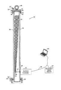
FIG. 1 is a schematic cross-sectional view of one embodiment of a
controlled aperture ball drop 30 in accordance with the invention. A
cylindrical ball cartridge 32 accommodates a ball rail 34 that supports a
plurality of frac balls 36 arranged in a predetermined size sequence in which
- 6 -
CA 02871203 2016-02-02
13523-86CA-2
32 is made of a copper beryllium alloy, which is nonmagnetic and has a very
high tensile strength. However, the ball cartridge 32 may also be made of
stainless steel, provided the material used has enough tensile strength to
contain fluid pressures that will be used to inject stimulation fluid into the
well
(generally, up to around 20,000 psi). The ball rail 34 is supported at a
bottom
end 38 by an aperture control arm 40 that extends through a port in a sidewall
of the ball cartridge 32 and is operatively connected to an aperture
controller
42. The aperture controller 42 incrementally moves the aperture control arm
40 to control a size of a ball drop aperture 44 between an inner periphery of
the ball cartridge 32 and the bottom end 38 of the ball rail 34. Exemplary
embodiments of the aperture controller 42 will be described below in detail
with reference to FIGs. 2-4. However, it should be understood that the
aperture controller 42 may be implemented using any one of: an alternating
current (AC) or direct current (DC) electric motor; an AC or DC stepper motor;
an AC of DC variable frequency drive; an AC or DC servo motor without a
mechanical rotation stop; a pneumatic motor; a hydraulic motor; or, a manual
crank.
A top end 46 of the ball cartridge 32 is sealed by a threaded top cap
48. In one embodiment the top cap 48 is provided with a lifting eye 49, and a
vent tube 50 that is sealed by a high pressure needle valve 51. The high
pressure needle valve 51 is used to vent air from the ball cartridge 32 before
a frac job is commenced, using procedures that are well understood in the art.
A high pressure seal is provided between the ball cartridge 32 and the top cap
48 by one or more high pressure seals 52. In one embodiment, the high
pressure seals 52 are 0-rings with backups 54 that are received in one or
more circumferential seal grooves 56 in the top end 46 of the ball cartridge
32. In one embodiment, a bottom end 58 of the ball cartridge 32 includes a
radial shoulder 60 that supports a threaded nut 62 for connecting the ball
drop
to a frac head or a high pressure fluid conduit using a threaded union as
30 described in Assignee's United States patent 7,484,776. As will be
- 7 -
-Substitute Page-
CA 02871203 2014-11-07
13523-86CA-2
understood by those skilled in the art, the bottom end 58 may also terminate
in an API (American Petroleum Institute) stud pad or an API flange, both of
which are well known in the art.
Movement of the aperture control arm 40 by the aperture controller 42
to drop a frac ball 36 from the ball cartridge 32, or to return to a home
position in which the bottom end 38 of the ball rail 34 contacts the inner
periphery of the ball cartridge 32, may be remotely controlled by a control
console 64. In one embodiment, the control console 64 is a personal
computer, though a dedicated control console 64 may also be used. The
control console 64 is connected to the aperture controller 42 by a
control/power umbilical 66 used to transmit control signals to the aperture
controller 42, and receive status information from the aperture controller 42.
The control/power umbilical 66 is also used to supply operating power to the
aperture controller 42. The control/power umbilical 66 supplies operating
power to the aperture controller 42 from an onsite generator or mains power
source 67. The aperture controller 42 is mounted to an outer sidewall of the
ball cartridge 32 and reciprocates the aperture control arm 40 through a high
pressure fluid seal 68. In one embodiment the high pressure fluid seal 68 is
made up of one or more high pressure lip seals, well known in the art.
Alternatively, the high pressure fluid seal 68 may be two or more 0-rings
with backups, chevron packing, one or more PolyPaks0, or any other high
pressure fluid seal capable of ensuring that highly pressurized well
stimulation fluid will not leak around the aperture control arm 40.
FIG. 2 is a schematic cross-sectional view of another embodiment of
a controlled aperture ball drop 30a in accordance with the invention. In this
embodiment the aperture controller 42a is mounted to a radial clamp 70
secured around a periphery of the ball cartridge 32 by, for example, two or
more bolts 72. A bore 74 through the radial clamp 70 accommodates the
aperture control arm 40. The aperture controller 42a is mounted to a support
plate 76 that is bolted, welded, or otherwise affixed to the radial clamp 70.
The aperture controller 42a has a drive shaft 78 with a pinion gear 80 that
- 8 -
CA 02871203 2014-11-07
13523-86CA-2
meshes with a spiral thread 82 on the aperture control arm 40. Rotation of
the drive shaft 78 in one direction induces linear movement of the aperture
control arm 40 to reduce a size of the ball drop aperture 44, while rotation
of
the drive shaft 78 in the opposite direction induces linear movement of the
aperture control arm 40 in the opposite direction to increase a size of the
ball
drop aperture 44. The unthreaded end of the aperture control arm 40 is a
chrome shaft, which is well known in the art.
FIG. 3 is a schematic cross-sectional view of an embodiment of a
controlled aperture ball drop 30b showing an aperture controller 42b in
accordance with one embodiment of the invention. In this embodiment the
aperture controller 42b has an onboard processor 84 that receives operating
power from an onboard processor power supply 86. Electrical power is
supplied to the processor power supply 86 by the onsite generator or mains
source 67 via an electrical feed 88 incorporated in the control/power
umbilical 66. The processor 84 sends a TTL (Transistor-Transistor Logic)
pulse for each step to be made by a stepper motor/drive 90, as well as a
TTL direction line to indicate a direction of rotation of the step(s), to the
stepper motor/drive unit 90 via a control connection 92. The TTL pulses
control rotation of the pinion gear 80 in response to commands received
from the control console 64. The stepper motor/drive unit 90 is supplied with
operating power by a motor power supply 94 that is in turn supplied with
electrical power via an electrical feed 96 incorporated into the control/power
umbilical 66. In one embodiment, the motor power supply 94 and the
stepper motor/drive 90 are integrated in a unit available from Schneider
Electric Motion USA as the MDrive034AC.
An output shaft 93 of the stepper motor/drive 90 is connected to an
input of a reduction gear 94 to provide fine control of the linear motion of
the
control arm 40. The reduction ratio of the reduction gear 94 is dependent on
the operating characteristics of the stepper motor/drive 90, and a matter of
design choice. The output of the reduction gear 94 is the drive shaft 78 that
supports the pinion gear 80 described above. In this embodiment, the
- 9 -
CA 02871203 2014-11-07
13523-86CA-2
aperture control arm 40 is connected to the bottom end of the ball rail 34 by
a ball and socket connection. A ball 95 is affixed to a shaft 96 that is
welded
or otherwise affixed to the bottom end of the ball rail 34. The ball 95 is
captured in a socket 97 affixed to an inner end of the aperture control arm
40. A cap 98 is affixed to the open end of the socket 97 to trap the ball 95
in
the socket 97. It should be understood that the aperture control arm 40 may
be connected to the ball rail 40 using other types of secure connectors know
in the art.
An absolute position of the aperture control arm 40 is provided to the
processor 84 via a signal line 100 connected to an absolute encoder 102. A
pinion affixed to an axle 104 of the absolute encoder 102 is rotated by a rack
106 supported by a plate 108 connected to an outer end of the aperture
control arm 40. In one embodiment, the absolute encoder 102 outputs to the
processor 84 a 15-bit code word via the signal line 100. The processor 84
translates the 15-bit code word into an absolute position of the aperture
control arm 40 with respect to the home position in which the bottom end 38
of the ball rail 34 contacts the inner periphery of the ball cartridge 32.
Since the ball drop 30b is designed to operate in an environment
where gaseous hydrocarbons may be present, the aperture controller 42b is
preferably encased in an aperture controller capsule 110. In one
embodiment the capsule 110 is hermetically sealed and charged with an
inert gas such as nitrogen gas (N2). The capsule 110 may be charged with
inert gas in any one of several ways. In one embodiment, N2 is periodically
injected through a port 112 in the capsule 110. In another embodiment, the
capsule 110 is charged with inert gas supplied by an inert gas cylinder 114
supported by the ball cartridge 32. A hose 116 connects the inert gas
cylinder 114 to the port 112. The capsule 110 may be provided with a bleed
port 122 that permits the inert gas to bleed at a controlled rate from the
capsule 110. This permits a temperature within the capsule to be controlled
when operating in a very hot environment since expansion of the inert gas
as it enters the capsule 110 provides a cooling effect. Gas pressure within
-10-
CA 02871203 2014-11-07
13523-86CA-2
the capsule 110 may be monitored by the processor 84 using a pressure
probe (not shown) and reported to the control console 64. Alternatively,
and/or in addition, the internal pressure in the capsule 110 may be displayed
by a pressure gauge 118 that measures the capsule pressure directly or
displays a digital pressure reading obtained from the processor 84 via a
signal line 120.
FIG. 4 is a schematic cross-sectional view of yet another embodiment
of a controlled aperture ball drop 30c in accordance with the invention. This
embodiment of is similar to the controlled aperture ball drop 30b described
above with reference to FIG. 3, except that all control and reckoning
functions are performed by the control console 64, and power supply for the
stepper motor/drive unit 90 is either integral with the unit 90 or housed with
a
generator/mains source/power supplies 67a. Consequently, the control
console 64 sends TTL pulses and TTL direction lines directly via the
control/power umbilical 66 to the stepper motor/drive unit 90 of an aperture
controller 42b to control movement of the aperture control arm 40. An
absolute position of the aperture control arm 40 is reported to the control
console 64 by the absolute encoder 102 via a signal line 100a in the
control/power umbilical 66. An internal pressure of the capsule 110 is
measured by a pressure sensor 118a, and reported to the control console
64 via a signal line 122 incorporated into the control/power umbilical 66. The
pressure sensor 118a optionally also provides a direct optical display of gas
pressure within the capsule 110.
FIG. 5 is a schematic cross-sectional view of a further embodiment of
a controlled aperture ball drop 30d in accordance with the invention. The ball
drop 30d is the same as the ball drop 30b described above with reference to
FIG. 3 except that it further includes an optical detector for detecting each
ball dropped by the ball drop 30d. In this embodiment, the optical detector is
implemented using a port 124 in a sidewall of the ball cartridge 32 opposite
the port that accommodates the aperture control arm 40. The port 124
receives a copper beryllium plug 126 that is retained in the port 124 by the
-11-
CA 02871203 2014-11-07
13523-86CA-2
radial clamp 70. A high pressure fluid seal is provided by, for example, one
or more 0-ring seals with backups 128 received in peripheral grooves in the
plug 126. An angled, stepped bore 130 in the plug 126 receives a collet 132
with an axial, stepped bore 134. An inner end of the axial stepped bore 134
retains a sapphire window 136. Two optical fibers sheathed in a cable 138
are glued to an inner side of the sapphire window 136 using, for example, an
optical grade epoxy. One of the optical fibers emits light generated by a
photoelectric sensor 140 housed in the aperture controller capsule 110. In
one embodiment, the photoelectric sensor 140 is a Banner Engineering
SM312FP. When a ball 36b is dropped by the controlled aperture ball drop
30d, the light emitted by the one optical fiber is reflected back to the other
optical fiber, which transmits the light to the photoelectric sensor 140. The
photoelectric sensor 140 generates a signal in response to the reflected light
and transmits the signal to the processor 84 via a signal line 142. The
processor 84 translates the signal and notifies the control console 64 of the
ball drop.
FIG. 6 is a schematic cross-sectional view of yet a further
embodiment of a controlled aperture ball drop 30e in accordance with the
invention. This embodiment is the same as the controlled aperture ball drop
30c described above with reference to FIG. 4 except that it further includes
the photo detector described above with reference to FIG. 5, which will not
be redundantly described. In this embodiment, however, the signal
generated by the photoelectric sensor 140 is sent via a signal line 142a
incorporated in the control/power umbilical 66 to the control console 64.The
control console 64 processes the signals generated by the photoelectric
sensor 140 to confirm a ball drop.
FIG. 7 is a schematic cross-sectional view of still a further
embodiment of a controlled aperture ball drop 30f in accordance with the
invention. This embodiment is the same as the embodiment described
above with reference to FIG. 3 except that it includes a mechanism for
tracking a height of the ball stack 36 supported by the ball rail 34, to
permit
- 12-
CA 02871203 2014-11-07
13523-86CA-2
the operator to verify that a frac ball has been dropped when a ball drop
command is sent from the control console 64. In this embodiment, a ball
stack follower150 rests on top of the frac ball stack 36. The ball stack
follower 150 encases one or more rare earth magnets 152. The ball stack
follower 150 has two pairs of wheels 154a and 154b that space it from the
inner periphery of the ball cartridge 32 to reduce friction and ensure that
the
ball stack follower readily moves downwardly with the ball stack 36 as frac
balls are dropped by the ball drop 30f.The rare earth magnet(s) 152 strongly
attracts oppositely oriented rare earth magnet(s) 156 carried by an external
ball stack tracker 158. The ball stack tracker 158 also has two pairs of
wheels 160a and 160b that run over the outer sidewall of the ball cartridge
32. The ball stack tracker 158 is securely affixed to a belt 162 that loops
around an upper pulley 164 rotatably supported by an upper bracket 166
affixed to the outer sidewall of the ball cartridge 32 and a lower pulley 168
rotatably supported by a lower bracket 170, likewise affixed to the outer
sidewall of the ball cartridge 32. The lower pulley 168 is connected to the
input shaft of a potentiometer 172, or the like. Output of the potentiometer
172 is sent via an electrical lead 174 to the processor 84, which translates
the output of the potentiometer 172 into a relative position of a top of the
ball
stack 36. That information is sent via the control/power umbilical 66 to the
control console 64, which displays the relative position of the top of the
ball
stack 36. This permits the operator to verify a ball drop and confirm that
only
the desired ball has been dropped from the ball stack 36.
As will be understood by those skilled in the art, the mechanism for
tracking the height of the ball stack 36 supported by the ball rail 34 can be
implemented in many ways aside from the one described above with
reference to FIG. 7. For example, a relative position of the ball stack
tracker
158 can be determined using a linear potentiometer, a string potentiometer,
an absolute or incremental encoder, a laser range finder, a photoelectric
array, etc.
-13-
CA 02871203 2014-11-07
13523-86CA-2
FIG.8 is a schematic cross-sectional view of another embodiment of a
controlled aperture ball drop 30g in accordance with the invention. The
controlled aperture ball drop 30g is the same as the controlled aperture ball
drop 30c described above with reference to FIG. 4 except that it further
includes the electro-mechanical ball stack tracking mechanism described
above with reference to FIG.7. In this embodiment, output of the
potentiometer 172 is sent via an electrical lead 174a incorporated in the
control/power umbilical 66 directly to the control console 64. The control
console 64 translates the output of the potentiometer 172 into a relative
position of a top of the ball stack 36 and displays the relative position of
the
top of the ball stack 36. This permits the operator to verify a ball drop and
confirm that only the desired ball has been dropped from the ball stack 36
after a ball drop command has been sent to the stepper motor/drive 90.
FIG. 9 is a schematic cross-sectional view of yet another embodiment
of a controlled aperture ball drop 30h in accordance with the invention. The
controlled aperture ball drop 30h is the same as the ball drop 30b described
above with reference to FIG. 3 except that it further includes both the
optical
detector described above with reference to FIG. 5 and the electro-
mechanical ball stack tracking mechanism described above with reference to
FIG. 7. The optical detector provides the operator with an indication that a
ball has been dropped and the redundant ball stack tracking mechanism
verifies that the frac ball stack 36 has moved downwardly by an increment
corresponding to a diameter of the frac ball dropped. Of course if either the
optical detector or the electro-mechanical ball stack tracking mechanism fails
during a well stimulation procedure, the remaining ball drop tracking
mechanism is likely to continue to function throughout the procedure so that
the operator always has confirmation each time a ball is dropped from the
controlled aperture ball drop 30h.
FIG. 10 is a schematic cross-sectional view of yet a further
embodiment of a controlled aperture ball drop 30i in accordance with the
invention. The controlled aperture ball drop 30i is the same as the ball drop
- 14-
CA 02871203 2014-11-07
13523-86CA-2
30c described above with reference to FIG. 4 except that it further includes
both the optical detector described above with reference to FIGs. 5 and 6,
and the electro-mechanical ball stack tracking mechanism described above
with reference to FIGs. 7 and 8. As explained above, the optical detector
provides the operator with an indication that a ball has been dropped and
the redundant ball stack tracking mechanism verifies that the frac ball stack
36 has moved downwardly by an increment corresponding to a diameter of
the frac ball dropped. As further explained above, if either the optical
detector or the electro-mechanical ball stack tracking mechanism fails during
a well stimulation procedure, the remaining ball drop tracking mechanism is
likely to continue to function throughout the procedure so that the operator
always has confirmation each time a ball is dropped from the controlled
aperture ball drop 30i.
FIG. 11 is a side elevational view of one embodiment of the ball rail
34 for the embodiments of the controlled aperture ball drop 30i shown in
FIGs. 1-10, and FIG. 12 is a schematic cross-sectional view of the ball rail
shown in FIG. 11, taken along line 12-12 of FIG. 11. In this embodiment the
ball rail 34 is substantially V-shaped in cross-section and constructed of 5
layers (200a-200e) of 14 gauge stainless steel welded together at
longitudinally spaced intervals (202a-202j) along opposite side edges. The
ball rail 34 is longitudinally curved to substantially conform to a curvature
of
the ball stack 36 intended to be dropped when the ball stack 36 is vertically
aligned along the inner periphery of the ball cartridge 32. However, the
cross-sectional shape of the ball rail 34 is the same along the length of the
ball rail, except at the bottom end 38 where a portion of the top edges of
some of the laminations are ground or cut away at 204 to allow the V at the
bottom end 38 to approach the inner periphery of the ball cartridge 32 close
enough to trap the smallest ball in the ball stack 36 to be dropped, e.g. a
bit
less than 3/4" (1.905 cm).
FIG. 13 is a table showing a deflection of the ball rail 34 shown in
FIG. 11 at points A, B and C under a 10 lb. (4.54 kg) mass at three spaced
-15-
CA 02871203 2014-11-07
13523-86CA-2
apart positions relative to the bottom end 38 of the ball rail 34. As can be
seen, the ball rail is quite stiff, which is a condition required to support
the
ball stack 36 in vertical alignment against the inner periphery of the ball
cartridge 36. In general, it has been observed that this degree of stiffness
of
the ball rail 34 is adequate to provide a functional ball rail 34.
FIG. 14 is a side elevational view of another embodiment of a ball rail
34a for the embodiments of the controlled aperture ball drops 30-30i shown
in FIGs. 1-10, and FIGs. 15-19 are schematic cross-sectional views of the
ball rail 34a shown in FIG. 14, respectively taken at lines 15-15, 16-16, 17-
17, 18-18 and 19-19 of FIG. 14. In this embodiment, the ball rail 34a is
constructed of a carbon fiber composite, which is known in the art. The ball
rail 34a is longitudinally curved to substantially conform to the curvature of
the ball stack 36 when the ball stack 36 is vertically aligned along the inner
periphery of the ball cartridge 32. The cross-sectional shape is substantially
constant from the top end to the bottom 38a of the ball rail 34a. However, a
height of the side edges decreases from top to bottom to ensure that 8-10 of
the smallest diameter frac balls to be dropped are maintained in a vertical
alignment in the ball cartridge 32.
Although these two examples of a ball rail 34 and 34a have been
described in detail, it should be noted that the ball rail 34 can be machined
from solid bar stock; cut from round, square, hexagonal or octagonal tubular
stock; or laid up using composite material construction techniques that are
known in the art. It should be further noted that there appears to be no upper
limit to the stiffness of the rail provide the rail is not brittle.
FIG. 20 is a schematic side elevational view of any one of the
controlled aperture ball drops 30a-30i shown in FIGs. 1-10 (hereinafter
collectively referred to as controlled aperture ball drop 30) housed in a
protective cabinet 300. As explained above the controlled aperture ball drop
must operate in open air environments exposed to the elements, as well
30 as pollutants such as dust, sand, flammable and/or corrosive liquids
and/or
vapors; etc. It is therefore been recognized that it is important to protect
the
- 16-
CA 02871203 2014-11-07
13523-86CA-2
exposed components of the controlled aperture ball drop 30 as much as
possible. The protective cabinet 300 provides a sealed closure that inhibits
the penetration of ultraviolet radiation, rain, snow or ice as well as any
dust,
sand, liquids or vapors. Access to the controlled aperture ball drop 30 is
provided through an access door 302 supported by hinges 304 in a manner
well known in the art. A door handle 306 is designed to maintain the door in
a closed position when the protective cabinet 300 is exposed to the
inevitable vibration generated during the large volume, high pressure frac
fluid pumping required during a well stimulation procedure.
FIG. 21 is a schematic view of a principal user interface 310 in
accordance with one embodiment of the invention displayed by the control
console 64. The control console 64 serves as the supervisory command
center and user interface for the controlled aperture ball drop 30. The
onboard processor 84 (for example, see FIG. 3) on the controlled aperture
ball drop 30 executes programmed instructions to interface with sensors and
the aperture control hardware, which will be explained below in more detail.
The control console 64 is connected to the onboard processor via a
communications channel supported by the umbilical 66. The
communications channel may be an Ethernet connection, for example.
When an operator (not shown) instructs the control console 64 to send a ball
drop command to the onboard processor 84, the onboard processor 84
operates autonomously to accomplish the ball drop and returns confirmation
data associated with the ball drop to the control console 64. The user
interface 310 permits the operator of the controlled aperture ball drop 30 to
configure a new ball stack; load the ball stack into the cylindrical ball
cartridge 32; drop balls from the ball stack in the size sequence in which
they were loaded; and, confirm that each ball was dropped when the
operator requested that it be dropped by the controlled aperture ball drop 30.
The user interface 310 provides the operator with 3 'action' buttons. These
are respectively used to: create a new ball stack 312; drop a frac ball 314
from a bottom of the frac ball stack 36; and, exit the program (STOP 316).
- 17-
CA 02871203 2014-11-07
13523-86CA-2
The user interface 310 also provides 3 status indicators that
respectively provide feedback to the operator to indicate whether the
controlled aperture ball drop 30 is functioning as expected. These status
indicators provide feedback to indicate: "Connected to Tool" 318, which
indicates that a valid communication connection is established between the
control console 64 and the onboard processor 84; "Position Correct" 320,
which indicates that the absolute encoder 102 (for example, see FIG. 7)
connected to the aperture control arm 40 correlates properly with an
expected position based on a number of balls that have been dropped; and,
"Follower Correct" 322, which indicates that the ball stack tracker 158 (see
FIG. 7) is properly coupled to the ball stack follower 150, which is atop the
frac ball stack 36 on the inside of the ball cartridge 32. In accordance with
one embodiment of the invention, the respective status indicators 318-322
display a green color if the corresponding monitored conditions are within
respective tolerances, and display a red color if they are not. It should be
understood that other visual indicators could also be used. For example, the
3 status indicators could display a solid color when the respective condition
is within tolerance and flash the same or a different color when the
respective condition is not within tolerance, etc.
The user interface 310 also provides a ball stack list 324 having
columns that respectively indicate: Drop status 326; ball Number 328; ball
Size 330; and drop Time 332. Each time a frac ball is dropped, the Drop
status 326 changes from "NO" to "YES" and the drop Time 332 changes
from blank to the current time at which the drop command was received by
the onboard processor 84. In one embodiment, the row for a next ball to be
dropped is also highlighted in a bright color.
Several data displays are also provided to assist the operator in
tracking a frac ball drop procedure. Those data displays include:
Balls Dropped 334 which in this example reads "0" because no balls
have yet been dropped.
-18-
CA 02871203 2014-11-07
13523-86CA-2
Pulse Count 336, which is the number of drive pulses that have been
sent by the onboard processor 84 to the stepper motor/drive 90 with respect
to "Home Position". The Home Position is a factory set position in which the
size of the ball drop aperture 44 between the bottom end of the ball rail 34
and the sidewall of the ball cartridge 32 retains the smallest frac ball
(0.7500") in the ball stack.
Home Position 338, which is expressed as a function of the absolute
encoder 102 count when the aperture control arm 40 is the Home Position.
In this example, the absolute encoder count is 3252 at the factory set Home
Position.
Encoder Count 340 is the actual current absolute encoder count
when the aperture control arm 40 has been driven to the Home Position
(Pulse Count 336 = 0). In this example, the Encoder Count is 3277. As
understood by those skilled in the art, exposure to high pressure frac fluids
stretches mechanical components that contain it and repeated use causes
mechanical wear. Consequently, the Encoder Count 3227 will often differ to
some extent from the factory set Home Position. Calc Encoder 342 is a
computed value of what the absolute encoder count should be, given the
Pulse Count 336. Calc Encoder 342 is computed as follows:
1 encoder count = 0.000144"
1 encoder count = 36.8 drive pulses; therefore:
Calc Encoder = Home Position + Pulse Count/36.8
Calc Diff 344 is Encoder Count 340 minus Calc Encoder. In this
example, Calc Diff 344 is 3277 ¨ 3252 = -25.
Follower Position 346 is the Position of the ball stack tracker 158 (see
FIG. 7, for example) expressed in inches from a bottom of the frac ball stack.
As will be explained below in detail, the Follower Position 346 is one data
-19-
CA 02871203 2014-11-07
13523-86CA-2
item used to determine when a frac ball has been dropped from the frac ball
stack 36.
Follower Delta 348 is Follower Position 346 at an end of a last ball
drop move of the aperture control arm 40, minus Follower Position 346 at an
end of a current ball drop move of the aperture control arm 40. In this
example, Follower Delta is equal to Follower Position 346 because a new
ball stack 36 has just been created and the ball stack tracker 158 has just
been moved from a bottom of the ball cartridge 32 to a top of the ball
cartridge 32 as shown for example in FIG. 7, where it is magnetically
coupled to the ball stack follower 150.
Ambient Temp 350 is a temperature inside the protective cabinet 300,
which must be monitored by the operator to ensure that the temperature
does not exceed predetermined operating limits.
9501 Code 352 displays an error code used to alert the operator
when the aperture controller 30 experiences an "under voltage fault"
condition, which can occur if the external power supply or the power supply
67, 67a is not connected, the power supplied does not meet minimum power
supply voltage specifications, or a short circuit develops; or an "over
voltage
fault" condition develops, which can occur when the external power supply
67, 67a voltage exceeds the power supply specifications of the controlled
aperture ball drop 30.
Last 9501 Code displays the previously displayed 9501 Code, if any,
for diagnostic purposes.
Zoom 356 button permits the operator to reposition a Y-axis of a
Follower Position graph 360 prior to a ball drop. The Follower Position graph
360 provides the operator with a graphical representation of a movement of
the ball stack tracker 158 in real time during a ball drop, as will be
explained
in detail below with reference to FIG. 32. The Zoom 356 button positions the
ball drop trace at a top of the Y-axis of the chart so the entire ball drop
event
will be displayed, because the Y-axis limits the range of values that can be
- 20 -
CA 02871203 2014-11-07
13523-86CA-2
displayed. This prevents the trace from dropping off of the graph during a
ball drop.
Drive Status 358 indicates whether the stepper motor/drive 90 is
enabled or disabled.
Follower Position graph 360 provides the operator with a graphical
representation of Follower Position 346, and as explained above.
The Drop Snapshot graph 362 provides the operator with a graphical
representation of the movement of the ball stack tracker 158 after a ball drop
is completed, as will also be explained below with reference to FIG. 32.
Check Nitrogen alarm indicator 364 alerts the operator if nitrogen
pressure within the aperture controller 42 drops below a predetermined
threshold. In one embodiment, the Check Nitrogen alarm indicator 364
displays a green color when the nitrogen pressure is within tolerance and
displays a red color when it is not within tolerance.
Admin button 366 permits authorized personnel to access
administration functions after an appropriate authentication has been
performed. Administration functions will be explained below with reference to
FIGs. 35 and 36.
FIG. 22 is a schematic view of the user interface shown in FIG. 21
overlaid by a configure new ball stack confirmation window 370, which is
displays if the operator selects the New Ball Stack 312 button. Since any
action by an operator can have significant consequences, every action must
be confirmed. Consequently, when the operator selects the New Ball Stack
312 button, the operator must confirm that action by selecting the OK button
372. If the New Ball Stack 312 button was selected by mistake, the operator
can select the Cancel 374 button to abort the new ball stack configuration
operation. New ball stacks are always created with the controlled aperture
ball drop 30 supported in a horizontal position on a trailer or other stable
flat
surface.
- 21 -
CA 02871203 2014-11-07
13523-86CA-2
FIG. 23 is a schematic view of the user interface shown in FIG. 21
overlaid by a load ball stack window 376, which is displayed after the
operator selects the OK button 372 on the configure new ball stack
confirmation window 370. When presented with this load ball stack window
376, the operator must select the New Ballstack button 378, or close the
window.
FIG. 24 is a schematic view of the load ball stack window 376 shown
in FIG. 23 overlaid by a Ballstack Prompt window 380. The Ballstack Prompt
window 380 requires three operator inputs: Starting Size 382, in which the
operator inputs the size of the smallest frac ball in the frac ball stack 36
to be
created; Increment 384, which is the size increment of the balls in the frac
ball stack. In this example, the size increment is 0.125 (1/8"); and, Number
of Balls 386, which is the total number of balls in the frac ball stack. These
three values must be input even if the size increment is not consistent
between all of the balls in the frac ball stack 36. This sometimes happens if
a
sliding sleeve was omitted when the production casing was installed,
because the frac ball size must match the sliding sleeve seat size, as
understood by those skilled in the art. If the size of a frac ball in the
newly
created ball stack has to be adjusted, the operator may accomplish that after
onboard processor 84 has created the new ball stack and it has been
displayed by the control console 64 in the Load Ballstack window 376. The
operator double clicks on any ball size(s) that must be adjusted, which
permits the ball size to be changed. After the three values 382, 384 and 386
are entered the operator selects the OK button 390.
FIG. 25 is a schematic view of the load ball stack window 376 shown
in FIG. 23 overlaid by a starting ball size confirmation window 382, which
appears after the operator selects the OK button 390. The operator must re-
enter the starting ball size at 384 and select the OK button 386 to permit the
control console 64 to pass the new ball stack information to the onboard
3D processor 84,
which executes programmed instructions to create the new
ball stack using the starting ball size, ball increment and number of frac
balls
- 22 -
CA 02871203 2014-11-07
13523-86CA-2
to be dropped to generate the ball stack list 324 described below in more
detail with reference to FIG. 35.
FIG. 26 is a schematic view of the load ball stack window 376 shown
in FIG. 23 overlaid by a drive to job home instruction window 388. Before
selecting the OK button 390, the operator must verify that the ball cartridge
is empty and clean so neither the ball rail 34 nor the aperture control arm 40
will be damaged when the ball rail is driven to the Home Position. Once the
operator selects the OK button, the onboard processor 84 drives the
aperture control arm 40 to the Home Position by sending the Pulse Count
366 number of reverse drive pulses to the stepper motor/drive 90.
FIG. 27 is a schematic view of the load ball stack window 376 shown
in FIG. 23 overlaid by a ball stack loaded acknowledgement window 394.
When presented with this window, the operator must load each frac ball onto
the ball rail 34 in the ball cartridge 32 in order of size sequence. After all
of
the frac balls are loaded, the top cap 48 is installed and the operator
selects
the OK button 396 or cancels the operation by selecting the Cancel button
398.
FIG. 28 is a schematic view of the load ball stack window 376 shown
in FIG. 23 overlaid by a ball stack loaded confirmation window 400, which is
displayed after the operator selects the OK button 396. The operator
confirms that each of the frac balls has been loaded in size sequence by
selecting the OK button 402. If all balls have not been loaded, the operator
must select the Cancel button 404. Once the OK button 402 has been
selected, the operator selects the Stop button 316. The Stop button 316
closes the user interface 310 and terminates the communication link
between the control console 64 and the onboard processor 84. The onboard
processor 84 continually checks for connections to the control console 64
until the external power supply 67, 67a is disconnected, which happens
when the operator physically switches off the onboard processor 84. . This
permits the controlled aperture ball drop 30 to be hoisted onto the frac stack
- 23 -
CA 02871203 2014-11-07
13523-86CA-2
and be mounted to a frac head or a high pressure fluid conduit so that a well
stimulation procedure can be commenced.
FIG. 29 is a flow chart depicting an algorithm that governs
programmed instructions executed by the onboard processor 84 to write
records to a data acquisition file. The programmed instructions execute
uninterruptedly after a ball stack is loaded and power is supplied to the
aperture controller. On power up the onboard processor 84 executes
programmed instructions that set Timer 1 at 402. In one embodiment, Timer
1 is set and reset to 10 seconds so that a data acquisition file record is
written every 10 seconds even during idle periods so long as a ball stack
exists and the controlled aperture ball drop 30 is powered on. The onboard
processor 84 routinely checks Timer 1 at 404 to determine if it has elapsed.
If not, the onboard processor 84 determines at 406 if the Stop button 316
has been selected, which powers down the controlled aperture ball drop 30.
If so, the process ends. If not the onboard processor returns to routinely
checking Timer 1 at 404. When Timer 1 has elapsed, Timer 1 is reset at 408,
data acquisition data values are acquired at 410 by the onboard processor
84. Each data acquisition file record contains the following data items:
Timestamp (Current date and time); Ball Number; Ball Size; Aperture
Control Arm State (Idle/Jog); Pulse Count; Encoder Count; Follower
Position; and, Temperature (in cabinet 300).
A data acquisition file record is then written at 412. After the data
acquisition file record is written, the onboard processor 84 recommences
monitoring Timer 1 at 404.
FIG. 30 is a flow chart depicting an algorithm that governs
programmed instructions executed by the onboard processor 84 to write
records to a ball drop data file. The onboard processor 84 executes the
programmed instructions uninterruptedly while onboard processor 84 is
operating the aperture control arm 40 to drop a frac ball. The ball drop data
file has a unique file name associated with the date/time the file was
- 24 -
CA 02871203 2014-11-07
13523-86CA-2
created. A new ball drop data file is created each time a new ball stack is
created. Data is written to the ball drop data file while the aperture control
arm 40 is being moved by the stepper motor/drive 90.
The onboard processor 84 continually monitors 420 a communication
channel established with the control console 64 for receipt of a ball drop
command. When a ball drop command is received, the onboard processor
84 sets 422 a Timer 2 to a predetermined time interval. In accordance with
one embodiment of the invention, Timer 2 is set to 0.1 seconds. The
onboard processor 84 then looks up 424, in a table created when the ball
stack was created by the onboard processor 84, the end sum for drive
pulses to be sent to the stepper motor/drive 90 in order to drop the next frac
ball. In accordance with one embodiment of the invention, when a new ball
stack is created, the onboard processor 84 examines the size of each ball to
be dropped, compares that size with the size of the previous frac ball to be
dropped, computes the difference in diameter and converts the difference to
drive pulses, which is then added to a current pulse count end sum to
compute a pulse count end sum for the ball to be dropped. 1 drive pulse
moves the aperture control arm 40 a linear distance of 0.0000037", so
32,000 drive pulses are required to move the aperture control arm 40 a
distance of 0.125", which is required to drop a frac ball that is 1/8" larger
than the last frac ball dropped. Alternatively, the onboard processor 84 may
compute the number of pulse counts required for each ball drop at 424 after
a ball drop command is input by the operator.
Once the pulse count end sum has been looked up, or otherwise
determined, the onboard processor 84 begins 426 sending drive pulses to
the stepper motor/drive 90. The onboard processor 84 continues to send
drive pulses to the stepper motor/drive 90 while determining 428 if the pulse
count equals the pulse count end sum. If not, the onboard processor 84
determines 430 if Timer 2 has elapsed while continuing to send drive pulses
to the stepper motor/drive 90. If Timer 2 has not elapsed, the onboard
processor 84 again checks the pulse count at 428. If Timer 2 has elapsed,
- 25 -
CA 02871203 2014-11-07
13523-86CA-2
the onboard processor 84: resets 432 Timer 2; acquires 434 ball drop data
values; and, writes 436 a ball drop file record, while continuing to send
drive
pulses to the stepper motor/drive 90. In accordance with one embodiment of
the invention the data values acquired at 434 are:
Timestamp (Current date and time); Ball Number; Ball Size; Pulse
Count; Encoder Count; Follower Position; and, Temperature (in cabinet
300).
In one embodiment of the invention, data gets written to the ball drop
data file for each of the parameters described above at a rate of once every
0.1 seconds. This records data associated with each parameter at a rate of
10 frames/second which enables analysis of exact drop points during the
movement of the aperture control arm 40. Periodically, the actual drop points
are compared to theoretical drop points to permit calibration adjustments to
Home Position be made, if necessary, as will be further described below with
reference to FIGS. 34-36.
After the ball drop file record is written, the onboard processor sends
the Follower Position acquired at 434 to the control console 64 to permit the
control console to paint the Follower Position graph 360, as will be explained
below with reference to FIG. 32, and checks the pulse count at 428. These
steps are repeated while the onboard processor 84 continues to send drive
pulses to the stepper motor/drive 90 until the pulse count equals the pulse
count end sum, as determined at 428. When the pulse count equals the
pulse count end sum, the onboard processor 84 sends data at 440 to the
control console 64 for frac ball drop confirmation processing, which will also
be explained below in more detail with reference to FIG. 32. Onboard
processor 84 then determines at 442 if the last frac ball has been dropped. If
so, ball drop processing ends. If not, the onboard processor 84 returns to
420 to monitor for a next ball drop command.
FIG. 31 is a schematic view of the principal user interface window 310
shown in FIG. 21 overlaid by a ball drop confirmation window 500, which is
- 26 -
CA 02871203 2014-11-07
13523-86CA-2
presented each time the operator presses function key F4 or selects the
Drop Ball button 314 to ensure that the operator intended to drop the next
frac ball from the frac ball stack 36. The operator is presented a with text
message that indicates the size of the next frac ball to be dropped and
requests confirmation of the ball drop. The operator may drop the ball by
selecting the OK button 502 or cancel the ball drop by selecting the Cancel
button 504. When the operator selects the OK button 502, the control
console sends a ball drop command to the onboard processor 84, which
performs the procedure described above with reference to FIG. 30.
FIG. 32 is a schematic view of the principal user interface window 310
immediately following completion of a ball drop, overlaid by a ball drop
confirmation information window 506, which presents the operator with
information about the position of the absolute encoder 172 and the ball stack
tracker 158 following the drop, to confirm that the ball drop has been
successful. Although this information is also available on the principal user
interface window 310 at Encoder Count 340; Calc Encoder 342 and Follower
Delta 348; it is redisplayed as Encoder Position 508; Follower Delta 510;
and, Calculated Encoder 512. In addition, color coded flags 509, 511
generated by the control console 64 respectively indicate whether the
Encoder Position 508 and Follower Delta 510 are within predetermined
tolerances. In one embodiment, the color coded flags 509 and 511 are
respectively a green color if those values are within their respective
tolerances and red if they are not. The operator may select the Confirm
button 514 or the Deny button 516, depending on the color of the respective
flags 509, 511. If the Deny button 516 is selected, the operator will normally
halt the well stimulation procedure until administrative assistance is
obtained
to resolve any malfunction. The operator is further assisted in deducing the
success of the ball drop by observation of the Follower Position graph 360
and the Drop Snapshot graph 362. As explained above, the Follower
Position graph 360 provides the operator with a graphical representation of a
movement of the ball stack tracker 158 in real time during a ball drop. The
resulting sloped line 518 is drawn by the control console 64 on the Follower
- 27 -
CA 02871203 2014-11-07
13523-86CA-2
Position graph 360 as the frac ball is dropped from the frac ball stack 36
using the follower position data sent by the onboard processor 84, as
described above with reference to FIG. 30.
The Drop Snapshot graph is drawn by the control console 64 after the
ball drop is completed using the ball drop confirmation data sent by the
onboard processor 84 to the control console 64, as also explained above
with reference to FIG. 30. The ball drop confirmation data includes: the data
values 334-354 described above with reference to FIG. 21, all Follower
Position data collected during the ball drop and the Timestamp associated
with each Follower Position data item. The Timestamp and the Follower
Position data items are used to paint the Drop Snapshot graph which plots
Follower Position on the Y-axis vs. time on the X-axis. The resulting graph
520 will clearly show the exact drop point of larger frac balls, though the
exact drop point of small frac balls may be less apparent due to side
stacking of the ball stack 36 on the ball rail 34.
FIG. 33 is a schematic view of a system for monitoring and
maintaining the controlled aperture ball drops 300 in accordance with the
invention. With dozens or hundreds of controlled aperture ball drops 300
operating in a wide geographical area, administration and maintenance
becomes a significant task. To enable effective administration and
maintenance of those tools, each controlled aperture ball drop 300 is
periodically monitored remotely by an administration facility 600 using a
remote data communication connection to the control console 64 to
determine the number of well stimulation jobs performed; and, when a
predetermined time has passed since last maintenance or a predetermined
number of well stimulation procedures have been performed, all ball drop
data is downloaded by the administration facility 600 for analysis. After
analysis of that data, remote adjustment of the Home Position may be
performed or onsite maintenance may be scheduled, as will be explained
below with reference to FIG. 34.
- 28 -
CA 02871203 2014-11-07
13523-86CA-2
FIG. 34 is a flow chart depicting principal steps performed during
scheduled and unscheduled maintenance of the controlled aperture ball
drops 300. As noted above, it is periodically determined at 700 if an elapsed
time since a last data analysis exceeds a threshold or the number of jobs
performed since a last data analysis exceeds a threshold. Alternatively, a
malfunction may be reported by an operator at 702. When any one of these
events occur, the administration facility 600 establishes a virtual
communications connection with the control console 64 and downloads 706
all Data Acquisition File records and the Ball Drop Data File records stored
by the onboard processor 84. That data is then analyzed to compare actual
frac ball drop points with the theoretical frac ball drop points to determine
the
effects of pressure, vibration and wear on the mechanical integrity of the
controlled aperture ball drop 30. Any noticeable migration of drop points is
addressed in one of two ways. If the migration is minor and consistent, it can
normally be addressed by a Home Position adjustment as determined at
710, and the adjustment is performed remotely at 716 using administration
tools that will be described below with reference to FIGs. 35 and 36, and the
process ends. If the migration is major or inconsistent, it is determined at
712 that onsite maintenance is required, a maintenance procedure is
scheduled 714, and the process ends.
FIG. 35 is a schematic view of an administrator interface 800 for the
controlled aperture ball drop in accordance with the invention showing a ball
drop observation data tab 801, which displays the same Follower Position
graph 360 and Drop Snapshot graph 362 seen by the operator. The
administrator interface 800 permits an administrator to take control of the
controlled aperture ball drop 30 to perform maintenance procedures or
recover from a malfunction. Control may be exercised locally or remotely via
a virtual connection established in a manner known in the art. The
administrator interface 800 displays all information and functions available
to
the operator, as well as the following inputs and action buttons used to
adjust the Home Position: a "Pulses to Jog" input 802 that permits the
administrator to input a whole number representing the number of drive
- 29 -
CA 02871203 2014-11-07
13523-86CA-2
pulses to be sent by the onboard processor 84 to the stepper motor/drive 90
in order to adjust the Home Position; a "Jog Open" button 804 that increases
a size of the aperture at the Home Position by the "Pulses to Jog" ; a "Jog
Closed" button 806 that decreases the size of the aperture at the Home
Position by the "Pulses to Jog"; a "Desired Encoder #" input 808 that permits
the administrator to input a whole number representing a desired position of
the aperture control arm 40 as represented by the Encoder number, which is
an alternative to "Pulses to Jog" for adjusting the Home Position; a "Move to
Encoder #" button 810, which prompts the control console 64 to instruct the
onboard processor 84 to move the aperture control arm 40 inwardly if the
"Desired Encoder #" is smaller than the Encoder Count 340, and prompts
the control console 64 to instruct the onboard processor 84 to move the
aperture control arm 40 outwardly if the "Desired Encoder #" is larger than
the Encoder Count 340; and, a "Set Home" button 811, which prompts the
control console 64 to instruct the onboard processor to set a current position
of the aperture control arm 40 as the Home Position and reset the Pulse
Count 336 to zero. As noted above, the Home Position is set so the aperture
size will securely retain a 0.750" frac ball. However, the Home Position is
not
set so that the first pulse count end sum will drive the aperture control arm
40 to an aperture size of 0.750". Because of additives and impurities in frac
fluids such as frac sand, etc., a frac ball cannot necessarily be expected to
drop from the rail 34 when the size of the aperture corresponds to the
diameter of the frac ball being dropped. In order to ensure a drop, Home
Position is set so that the first pulse count end sum will drive the aperture
control arm 40 to an aperture size that is about 20% greater than the
diameter of the first frac ball to be dropped.
A "Clear Ballstack" button 814 is provided to permit the administrator
to clear ball stack information from the memory of the onboard processor 84.
The "Clear Ballstack" button also removes all ball stack information from the
ball stack list 324.
- 30 -
CA 02871203 2014-11-07
13523-86CA-2
The administrator interface 800 also provides an "Override Encoder
Alarm" button 816 that permits the administrator to override an Encoder
Alarm. The Encoder Alarm disables the stepper motor/drive 90 if the
absolute encoder 102 senses that the aperture control arm 40 is being
driven past its normal operational range. This can occur if the control
software has an error (bug) in it or if an administrator sets up a 'jog' with
the
wrong number in the Pulses to Jog 802. The stepper motor/drive 90 is
powerful enough to damage to the controlled aperture ball drop 30 if it
moves beyond its operational range. Consequently, a field programmable
gate array (FPGA) (not shown) is programmed to monitor for out of range'
operation and to disable the stepper motor/drive 90 when the operational
range is breached. However, there are instances when it is advantageous to
drive the aperture control arm 40 without a functional absolute encoder 102.
If the absolute encoder 102 fails, it outputs a reading of "0". Since this is
out
of the range of normal operation, the FPGA disables the stepper motor/drive
90. If this happens in the middle of a well stimulation procedure, the
Override Encoder Alarm button 816 permits the well stimulation procedure to
be finished using the secondary feedback of the Follower Position 360 and
Drop Snapshot 362 to confirm ball drops without feedback from the absolute
encoder 102.
FIG. 36 is a schematic view of the administrator interface 800 for the
controlled aperture ball drop 30 showing a ball drop data tab 830. The ball
drop data tab 830 displays information maintained by the control console 64
for each frac ball dropped until a new ball stack is configured. The
information displayed includes all of the information displayed on the ball
stack list 324, namely: Dropped status (YES/NO) 832; Ball # 834; Ball Size
836 and Time Dropped (dd/mm/yy/hh/mm/ss) 838. Also displayed using data
sent to the control console 64 by the onboard processor 84 at 440 (FIG. 30)
are the following: start position of the ball stack tracker 158 (Start 840);
end
position of the ball stack tracker 158 (End Follower 842); change in the
position of the ball stack tracker 158 (Delta 844, i.e. End Follower 842 minus
Start 840); absolute encoder 102 number (Encoder 846); calculated encoder
- 31 -
CA 02871203 2014-11-07
13523-86CA-2
number (Calc. Enc. 848); pulse count start (Start 850); pulse count end
(Pulse End 852); pulse count end sum (Calc. End 854). This information is
analyzed by the administrator to determine the cause of a malfunction
and/or plan a recovery from the malfunction.
The embodiments of the invention described above are only intended
to be exemplary of the controlled aperture ball drop 30a-30i in accordance
with the invention, and not a complete description of every possible
configuration. The scope of the invention is therefore intended to be limited
solely by the scope of the appended claims.
- 32 -