Note: Descriptions are shown in the official language in which they were submitted.
Title: ACOUSTIC NOISE REDUCING RF COIL FOR MAGNETIC RESONANCE
IMAGING
CROSS-REFERENCE TO RELATED APPLICATIONS
[0001] This application claims the benefit of U.S. Provisional
Application No.
611640,058, filed April 30, 2012..
FIELD OF THE INVENTION
[0002] The present disclosure relates generally to hardware used in Magnetic
Resonance
MR) imaging systems, and more particularly, to systems and methods for
constructing Radio
Frequency (RF) coils which attenuate acoustic noise generated during MR
scanning.
BACKGROUND
[0003] The following description includes information that may be useful in
understanding
the present subject matter. It is not an admission that any of the information
provided herein
is prior art or relevant to the presently claimed subject matter, or that any
publication
specifically or implicitly referenced is prior art.
[0004] Magnetic Resonance imaging (MR1) employs a strong magnetic field that
is used to
polarize the spin magnetization in a patient's body. The spin magnetization
that is most often
used in .MRI arises from the nuclei of hydrogen atoms within the body.
Although the highest
concentration of hydrogen atoms within the body is found in water molecules,
other
compounds found in the body (e.g. lipids, glucose, etc.) are present in
sufficient concentration
to provide a detectable MR spin magnetization.
[0005] When the hydrogen atoms of a patient's body are introduced into the
polarizing
magnetic field, the spin magnetization of the hydrogen atom nuclei align in
one of two states:
with the magnetic field, or against the magnetic field. These two states
occupy slightly
different mew levels in a quantum mechanical system. By convention, the lowest
energy
level is called the ground state. It should be noted that the population of
nuclear spins in the
ground state is slightly higher than that of the higher energy state,
resulting in a net
magnetization of the macroscopic group of nuclei.
CA 2871384 2019-04-17
CA 02871384 2014-10-23
WO 2013/165470
PCT/US2012/071220
[0006] The energy difference between the two energy levels is directly
proportional to the
strength of the polarizing magnetic field. Thus. as the strength of the
magnetic field is
increased, the energy difference between the two states increases. The energy
differences
associated with typical MRI systems correspond to electromagnetic waves in the
radiofrequency range. The specific frequency associated with the difference is
called the
Larmor frequency (typically given in MHz). The constant of proportionality
that defines the
relationship between the polarizing field (typically given in Tesla) and the
Larmor frequency
is a natural constant called the gromagnetic ratio. This constant is unique
for each MR active
element. For Magnetic Resonance Imaging systems used in medicine, polarizing
magnetic
field fields are typically between 0.5 and 3.0 Tesla. For hydrogen atoms,
these polarizing
magnetic field strengths result in Larmor frequencies between 21.3 and 127.8
MHz.
[0007] If the nuclear spin system immersed in a polarizing magnetic field is
subjected to a
rotating magnetic field at the Larmor frequency, the spin system will absorb
energy and the
distribution of nuclear spins in the two energy states will be disturbed. The
duration of the
rotating magnetic field used to change the distribution of nuclear spins in
the two energy
states is typically limited, and applied with a strength sufficient to nutate
the net spin
magnetization from the longitudinal axis (i.e. parallel with the applied
polarizing magnetic
field) to the transverse plane (i.e. perpendicular to the applied polarizing
field). The term "RF
pulse" is conventionally used to describe this process since nutation is
accomplished with a
rotating magnetic field in the radiofrequency range and having a finite
duration.
[0008] With time, the energy will be emitted by the spin system in a fashion
that can be
detected with a sensitive pickup coil. This phenomenon is typically called
"resonance". The
absorption and re-emission of an RF signal is key to the formation of an MR
image.
[0009] When an MR signal is created, the frequency of the signal is precisely
proportional to
the strength of the magnetic field experienced by the nuclear spins. If all of
the spins in a
patient's body are in an identical magnetic field, then all the spins will
resonate with the same
frequency. Even though signals come from many different portions of the body,
the MR
imaging system has no way to distinguish one signal from another.
polo] In order to provide spatial encoding of the MR signals (and hence enable
the
formation of an image), it is useful to create a transient inhomogeneity in
the magnetic field.
In typical MRI imaging systems this is accomplished with magnetic field
gradient coils.
2
CA 02871384 2014-10-23
WO 2013/165470
PCT1US2012/071220
Gradient coils typically are designed to create a magnetic field whose
strength varies in a
linear fashion over a selected volume within the magnet. Gradient coil sets
are typically
constructed to permit gradient fields to be created in three orthogonal
directions within the
bore of the magnet. Typical gradient coils driven by typical gradient
amplifiers can generate a
magnetic field gradient of 20 mT/m in less than I ms, and maintain that
gradient with high
fidelity for an extended period limited only by the heat dissipation of the
gradient coils and
amplifier.
[0011] A typical imaging system creates an image by employing a sequence of RE
and
magnetic field gradient pulses to establish a detectable MR signal in a
selected plane. This
signal is then spatially encoded using magnetic field gradient pulses to
impart phase and
frequency shifts to the MR. signal which reveal the location of the signal
source within the
bore of the magnet. By selecting pulse sequence repetition times (TR), echo
times (TE) and
other pulse sequence parameters, the operator can tune the pulse sequence to
be sensitive to a
variety of intrinsic MR parameters found in the tissue of the patient (e.g.
longitudinal
relaxation time, Tj, Transverse relaxation time, 1'2, and the like). Many
pulse sequences are
'mown to those skilled in the state of the art. These pulse sequences can
collect data in two or
three dimensions. They can also collect data in Cartesian, radial or spiral
frameworks.
[0012] One aspect common to all MR imaging pulse sequences is that they employ
transient
magnetic field gradients. These transient gradient pulses are created by
running electrical
current through the gradient coils that are located within the bore of the
magnet. Current
running through these coils creates a mechanical force that results in a small
physical
displacement of th.e coil and its structure. Because of the temporal duration
of these gradient
pulses, acoustic noise is created. Despite aggressive engineering measures to
minimize the
amplitude of these physical displacements, MR imaging systems can be loud and
hearing
protection for the patient is required. The volume of acoustic noise created
by a particular
pulse sequence depends on many factors including th.e stiffness of the
gradient coil
construction, the strength of the various gradient pulses used in the imaging
sequence, and the
timing of the sequence. Acoustic noise levels in some MR scanners can be has
high as 120
dBA..
[0013] In view of the foregoing, it may be understood that the reduction of
acoustic noise
during MR scanning is desirable, and may serve to increase patient comfort and
tolerance for
scanning.
3
CA 02871384 2014-10-23
WO 2013/165470
PCT1US2012/071220
SUMMARY
[0014] Embodiments of the present disclosure provide a RF MR imaging coil
whose
construction also serves to attenuate acoustic noise created by the MRI
system's gradient
coils. In an embodiment, the RF MR imaging coil is a body coil which is
permanently
mounted in a large magnet and is made to be integral to the magnet assembly.
In an alternate
embodiment the RF MR imaging coil can be removable and exchangeable. Such an.
approach
may be desirable in smaller magnets designed for orthopedic andior neonatal MR
imaging.
[0015] In an exemplary embodiment of the present invention, an RF excitation
coil having a
"birdcage" topology is constructed using foam substrates for mechanical
support such that no
rigid elements are used to connect the RF coil to the interior wall of the
gradient system. The
materials chosen for the substrate are intended to minimize the propagation of
mechanical
vibrations from the MR system's gradient coils to the bore of the imaging
system where the
patient is lying, thereby reducing the acoustic noise exposure to the patient.
Birdcage coils
can have: a "high-pass" topology in which capacitors are placed in the end-
rings and the
rungs are comprised of inductive elements, a "low-pass" topology in which the
end rings
have inductive elements and one or more capacitors are placed in the rungs, or
a "band-pass"
topology in which capacitors and inductors are found in both end rings and
rungs.
[0016] In another exemplary embodiment, the RF excitation coil is used for
both exciting and
receiving the MR signals.
[0017] In another exemplary embodiment, both an RF shield and an RF coil are
incorporated
into an integrated assembly, with the RF shield placed around the excitation
coil. In this
configuration, the RF coil is mechanically decoupled from the RF shield by the
foam
substrate.
[0018] In another exemplary embodiment, the RF excitation coil has a
Transverse Electro-
Magnetic (TEM) topology. The TEM topology is similar to a birdcage topology,
but
incorporates discrete current return paths for each rung.
[0019] In another exemplary embodiment, a foam plug is used to substantially
enclose one
end of the RF coil. This plug serves to further reduce the acoustic noise,
while allowing the
patient to enter the coil from the opposite end.
4
CA 02871384 2014-10-23
WO 2013/165470
PCT/US2012/071220
[0020] In another exemplary embodiment, one or more vibration isolation
suspension
members are used to support the weight of the RF coil inside the integrated
coil assembly.
[0021] Support for invention will now be described in more detail with
reference to
exemplary embodiments thereof as shown in the accompanying drawings. While
support for
the invention is below with reference to exemplary embodiments, it should be
understood that
the scope of the invention is not limited thereto. Those of ordinary skill in
the art having
access to the teachings herein will recognize additional implementations,
modifications, and
embodiments, as well as other fields of use, Which are within the scope of the
invention as
described herein, and with respect to which the invention may be of
significant utility,
BRIEF DESCRIPTION OF THE DRAWINGS
[0022] In order to facilitate a fuller understanding of the present invention,
reference is now
made to the accompanying drawings, in which like elements arc referenced with
like
numerals. These drawings should not be construed as limiting the present
invention, but are
intended to be exemplary only.
[0023] In the drawings:
FIG. 1 shows an exemplary MRI system in or for which the present disclosure
may
be implemented;
FIG. 2 shows an exemplary high-pass birdcage RF coil suitable for
incorporation
with an embodiment of the present disclosure;
FIG. 3 shows an exemplary low-pass birdcage RF coil suitable for incorporation
with
an embodiment of the present disclosure;
FIG. 4 shows an exemplary construction for a sound-reducing RF coil in
accordance
with an embodiment of the present disclosure;
FIG. 5 shows a mid-line longitudinal cross section of a sound-reducing RF coil
in
accordance with an embodiment of the present disclosure;
FIG. 6 shows a radial cross section of a sound-reducing PI' coil in accordance
with an
embodiment of the present disclosure; and
CA 02871384 2014-10-23
WO 2013/165470
PCT1US2012/071220
FIG. 7 shows a radial cross section of a sound-reducing RF coil of an
alternate
embodiment of the present disclosure, in which suspension elements are
employed.
DETAILED DESCRIPTION
[0024] Embodiments of the present disclosure provide RF coils for use in
Magnetic
Resonance scanners which provide RF excitation and detection of MR signals
while
attenuating the acoustic noise generated by the scanner.
[0025] MR. imaging of internal body tissues may be used for numerous medical
procedures,
including diagnosis and surgery. In general terms, MR imaging starts by
placing a subject in
a relatively uniform, static magnetic field. The static magnetic field causes
hydrogen nuclei
spins to align and precess about the general direction of the magnetic field.
Radio frequency
(RF) magnetic field pulses are then superimposed on the static magnetic field
to cause some
of the aligned spins to alternate between a temporary high-energy nonaligned
state and the
aligned state, thereby inducing an RF response signal, called the MR echo or
MR response
signal. It is known that different tissues in the subject produce different MR
response signals,
and this property can be used to create contrast in an MR image. An RF
receiver detects the
duration, strength, and source location of the MR response signals, and such
data are then
processed to generate tomographic or three-dimensional images.
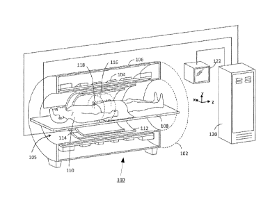
[0026] FIG. 1 shows an exemplary MRI system 100 in or for which MR imaging in
accordance with the present disclosure may be implemented. The illustrated MRI
system 100
comprises an MRI magnet assembly 102. Since the components and operation of
the MRI
scanner are well-known in the art, only some basic components helpful in the
understanding
of the system 100 and its operation will be described herein.
[0027] The MRI magnet assembly 102 typically comprises a cylindrical
superconducting
magnet 104, which generates a static magnetic field within a bore 105 of the
superconducting
magnet 104. The superconducting magnet 104 generates a substantially
homogeneous
magnetic field within an imaging region 116 inside the magnet bore 105. The
superconducting magnet 104 may be enclosed in a magnet housing 106. A support
table 108,
upon which a patient 110 lies, is disposed within the magnet bore 105. A
region of interest
118 within the patient 110 may be identified and positioned within the imaging
region 116 of
the MRI magnet assembly 102.
6
CA 02871384 2014-10-23
WO 2013/165470
PCT/US2012/071220
[0028] A set of cylindrical magnetic field gradient coils 112 may also be
provided within the
magnet bore 105. The gradient coils 112 also surround the patient 110. The
gradient coils 112
can generate magnetic field gradients of predetermined magnitudes, at
predetermined times,
and in three mutually orthogonal directions within the magnet bore 105. With
the field
gradients, different spatial locations can be associated with different
precession frequencies,
thereby giving an MR image its spatial resolution. An RF transmitter coil 114
surrounds the
imaging region 116 and the region of interest 118. The RF transmitter coil 114
emits RF
energy in the form of a rotating magnetic field into the imaging region 116,
including into the
region of interest 118.
[0029] The RF transmitter coil 114 can also receive MR response signals
emitted from the
region of interest 118. The MR response signals are amplified, conditioned and
digitized into
raw data using an image processing system 120, as is known by those of
ordinary skill in the
art. The image processing system 120 further processes the raw data using
known
computational methods, including fast Fourier transform (HT), into an array of
image data.
The image data may then be displayed on a monitor 122, such as a computer CRT,
LCD
display or other suitable display.
[0030] FIG. 2 illustrates one embodiment of RF transmitter coil 114. This coil
is a high-pass
birdcage coil assembly 200 that is well known to those skilled in the art. The
coil is
comprised of a set of inductive rungs 204 that are connected to two end rings
202. Within
each end ring 202 the electrical connection between each of the inductive
rungs 204
incorporates a capacitive element 206. The inductance of inductive rungs 204
and the
capacitance of capacitive elements 206 are chosen so that the high-pass
birdcage coil
assembly 200 resonates at the Larmor frequency of the MR scanner, and such
that this
resonant mode creates a rotating magnetic field in the center of the assembly.
It is typically
desirable to construct inductive rungs 204 so that each has substantially the
same inductance,
and to construct capacitive elements 206 so that each has substantially the
same capacitance.
This constancy among elements is typically needed to maximize the homogeneity
of the
rotating magnetic field.
[0031] FIG. 2 also shows the incorporation of an RF shield 208. This shield is
an optional
element of coil assembly 200. RF shield 208 serves to contain the
electromagnetic fields
generated by electrical currents flowing in the inductive rungs. An ideal RF
shield 208 acts as
a conductor at the Larmor frequency. while appearing to be non-conducting at
the frequency
7
CA 02871384 2014-10-23
WO 2013/165470
PCT1US2012/071220
of the gradient pulses created by the gradient coils 112. RF shield 208 can be
constructed
with a thin sheet of conducting material such as copper, a mesh, or it can
have a slotted
design to minimize gradient pulse-induced eddy currents. Note that if the RF
transmitter coil
114 is small with respect to the magnet bore 105, RF shield 208 may not be
required. This is
commonly the case for birdcage bead coils.
[0032] FIG. 3 illustrates a second embodiment of RF transmitter coil 114. This
coil is a low-
pass birdcage coil assembly 300 that is well known to those skilled in the
art. The coil is
comprised of a set of rungs 304 that are connected to two end rings 302.
Within each end ring
302 a direct electrical connection is made between each of the rungs 304. Each
rung 304
incorporates a capacitive element 306. The inductance of the end rings 302 and
the
capacitance of capacitive elements 306 are chosen so that the low-pass
birdcage coil
assembly 300 resonates at the Lanuor frequency of the MR scanner, and such
that this
resonant mode creates a rotating magnetic field in the center of the assembly.
It is typically
desirable to construct rungs 304 to be substantially the same, and to
construct capacitive
elements 306 so that each has substantially the same capacitance. This
constancy among
elements is typically needed to maximize the homogeneity of the rotating
magnetic field.
[0033] FIG. 3 also shows the incorporation of an RF shield 308. This shield is
an optional
element of coil assembly 300 and serves the same purpose as RF shield 208
described in FIG.
2.
[0034] The construction of the RF coils shown in FIGs 2 and 3 is that the RF
coil is
physically attached to the MRI magnet assembly 102. This attachment serves to
position the
RF transmitter coil 114 inside magnet bore 105. In prior art embodiments of RF
transmitter
coil 114, the attachment is accomplished using rigid elements that propagate
vibrations from
the gradient coils to the RF transmitter coil 114. These vibrations then
propagate to the
patient 110 and are perceived as acoustic noise. Acoustic noise is also
propagated through the
air space between the gradient coil and the inner bore of RF transmitter coil
114.
[0035] FIG. 4 shows a preferred embodiment of the present invention. In this
embodiment a
quiet RF coil assembly 400 is shown. Quiet RF coil assembly 400 is comprised
of an RF coil
substrate 404 upon which RF coil components 406 are mounted. Examples of RF
coil
component; 406 include the capacitors and inductive elements shown in FIGs 2
and 3. RF
coil substrate 404 can be constructed with fiberglass, plastic, ceramic or any
other MR-
compatible material that is suitable for mounting RF coil components 406.
Quiet RF coil
8
CA 02871384 2014-10-23
WO 2013/165470
PCT/US2012/071220
assembly 4(X) is further comprised of an RF coil cavity 412 that is filled
with a sound
absorbing substance. In the preferred embodiment of the present invention,
this sound
absorbing substance is an open-cell foam such as foam rubber. In alternate
embodiments, the
sound absorbing substance can include putty, gel, cloth batting, sponge, or
the like.
[0036] An aspect of the present invention is that there are no rigid
components connecting
the RF coil components to the outside of the assembly. This greatly reduces
the propagation
of sound vibrations from the gradient coils 112 to the inner bore of the RF
coil, and thus
reduces the acoustic sound level experienced by the patient 110.
[0037] The sound absorbing material filling RF coil cavity 412 is contained
within an RF coil
shell 414. In one preferred embodiment of the present invention RF coil shell
414 is
constructed with a flexible cloth-like material. This cloth-like material can
be constructed of
vinyl, plastic, or cloth. It can also have a complex construction such as
rubberized cloth. RF
coil shell 414 serves to encapsulate the RF coil substrate 404, the RF coil
components 406,
the RF coil cavity 412, and the sound absorbing material contained therein. RF
coil shell 414
also serves to substantially alien the RE' coil substrate 404 within the quiet
RE' coil assembly
400. In FIG. 4 RF coil shell 414 is shown to entirely encapsulate the full
assembly, including
its inner bore 418. In alternate embodiments of the preferred invention. RF
coil shell 414 can
be truncated to allow the contents of RF coil cavity 412 to come in direct
contact with the
walls of the gradient coils 112.
[0038] In another embodiment of the present invention, an end cap 420
constructed with
sound-absorbing material may be inserted at one end of the inner bore 418. If
desired, end
cap 420 can be constructed of the same sound absorbing material found in RF
coil cavity 412,
and use the same flexible cloth-like material used for RF coil shell 414.
[0039] In one embodiment of the present invention, the quiet RF coil assembly
is
permanently fixed in the MRI system's magnet. In another embodiment the coil
is removable.
A removable body coil may be useful in smaller magnets intended for orthopedic
and/or
neonatal applications where it is desirable to select an RF coil whose size is
matched to the
anatomy being imaged.
[0040] In the present invention, the electrical design of the RF coil is not
intended to be
limited. RF coil assemblies incorporating low-pass birdcage, high-pass
birdcage, band-pass
birdcage and TEM topologies are all within the scope of the invention.
Likewise, RF coil
9
CA 02871384 2014-10-23
WO 2013/165470
PCT/US2012/071220
assemblies that provide transmit-only, transmit/receive, and receive-only
functionality are
within the scope of the invention.
[0041] FIG. 5 shows a preferred embodiment of the present invention in greater
detail. In this
embodiment, a longitudinal cross section of a quiet RF coil assembly 5(X) is
shown. Quiet RF
coil assembly 500 is comprised of an RF coil substrate 502 upon which RF coil
components
are mounted. Two such components are shown in FIG. 5: a birdcage rung 504 and
birdcage
capacitor 506. These components are shown in a configuration consistent with
the high-pass
birdcage coil design shown in FIG. 2, but it should be readily appreciated
that alternate RF
coil constructions such as low-pass birdcage, band-pass birdcage and TEM
configurations are
included in the spirit of the invention. RF coil substrate 502 can be
constructed with
fiberglass, plastic, ceramic or any other MR-compatible material that is
suitable for mounting
birdcage rung 504 and birdcage capacitor 506. Quiet RF coil assembly 500 is
further
comprised of an RF coil cavity 512 that is tilled with a sound absorbing
substance 513
(shown in FIG. 5 as an array of dots). In the preferred embodiment of the
present invention,
this sound absorbing substance 513 is an open-cell foam such as foam rubber.
In alternate
embodiments, the sound absorbing substance can include putty, gel, cloth
batting, sponge, or
the like. Note that if desired, air gaps can be left around selected
components. Air gaps may
prove useful for heat dissipation and/or to reduce the likelihood of voltage
breakdown.
[0042] Quiet RE coil assembly 500 is further comprised of an RF shield 508
mounted on an
RF shield substrate 510. RF shield 508 can be constructed with a conducting
sheet of copper,
a conducting mesh or a slotted conductor. RF shield substrate 510 can be
constructed with a
rigid material such as fiberglass, plastic, ceramic or the like.
[0043] The sound absorbing material 513 filling RF coil cavity 512 is
contained within an RF
coil shell 514. In one preferred embodiment of the present invention RF coil
shell 514 is
constructed with a flexible cloth-like material. This cloth-like material can
be constructed of
vinyl, plastic, or cloth. It can also have a complex construction such as
rubberized cloth. RE
coil shell 514 serves to encapsulate the RF coil substrate 502, the birdcage
rungs 504, the
birdcage capacitors 506, the RF coil cavity 512, and the sound absorbing
material contained
therein. RF coil shell 514 and the sound absorbing material contained in RF
coil cavity 512
also serve to substantially align RF coil substrate 502 within the quiet RE
coil assembly 500.
In FIG. 5 RF coil shell 514 is shown to entirely encapsulate the assembly,
including surfaces
at the inner bore diameter 518 and outer bore diameter 516. In alternate
embodiments of the
CA 02871384 2014-10-23
WO 2013/165470
PCT/US2012/071220
preferred invention, RF coil shell 514 can be truncated to allow the RF shield
substrate 510 to
come in direct contact with the walls of the gradient coils 112.
[0044] FIG. 6 shows another preferred embodiment of the present invention in
greater detail.
In this embodiment, a radial cross section of a quiet RE coil assembly 600 is
shown. This
radial cross section shows one of the end rings of a high-pass birdcage coil.
Quiet RF coil
assembly 600 is comprised of an RF coil substrate 502 upon which RF coil
components are
mounted. Three such components are shown in FIG. 6: a set of eight birdcage
rungs 504, a set
of eight birdcage capacitors 506 and a birdcage circuit board 505. These
components are
shown in a configuration consistent with the high-pass birdcage coil design
shown in FIG. 2,
but it should be readily appreciated that alternate RF coil constructions are
included in the
spirit of the invention. RF coil substrate 502 can be constructed with
fiberglass, plastic,
ceramic or any other MR-compatible material that is suitable for mounting
birdcage rungs
504, birdcage capacitors 506, and circuit board 505. Quiet RF coil assembly
600 is further
comprised of an RF coil cavity 512 that is filled with a sound absorbing
substance 513
(shown in FIG. 6 as an array of dots. In the preferred embodiment of the
present invention,
this sound absorbing substance 513 is an open-cell foam such as foam rubber.
In alternate
embodiments, the sound absorbing substance can include putty, gel, cloth
batting, sponge, or
the like. Note that if desired, air gaps can be left around selected
components. Such gaps may
prove useful for heat dissipation and/or to reduce the likelihood of voltage
breakdown.
[0045] Quiet RF coil assembly 600 is further comprised of an RE shield 508
mounted on an
RF shield substrate 510. RF shield 508 can be constructed with a conducting
sheet of copper,
a conducting mesh or a slotted conductor. RF shield substrate 510 can be
constructed with a
rigid material such as fiberglass. plastic, ceramic or the like.
[0046] The sound absorbing material filling RF coil cavity 512 is contained
within an RF coil
shell 514. In one preferred embodiment of the present invention RE coil shell
514 is
constructed with a flexible cloth-like material. This cloth-like material can
be constructed of
vinyl, plastic, or cloth. It can also have a complex construction such as
rubberized cloth. RP'
coil shell 514 serves to encapsulate the RF coil substrate 502, the birdcage
rungs 504, the
circuit board 505, the RF coil cavity 512, and the sound absorbing material
contained therein.
RF coil shell 514 and the sound absorbing material contained in RF coil cavity
512 also serve
to substantially align RF coil substrate 502 within the quiet RF coil assembly
600. In FIG. 6
RF coil shell 514 is shown only on the surface of the inner bore diameter 518.
In alternate
embodiments of the preferred invention, RF coil shell 514 can be extended to
the exterior of
11
CA 02871384 2014-10-23
WO 2013/165470
PCT1US2012/071220
the assembly to prevent RF shield substrate 510 from coming in direct contact
with the walls
of the gradient coils 112.
[0047] FIG. 7 shows another preferred embodiment of the present invention in
greater detail.
In this embodiment, a radial cross section of a quiet RE coil assembly 700 is
shown. This
radial cross section shows one of the end rings of a low-pass birdcage coil.
Quiet RF coil
assembly 700 is comprised of an RF coil substrate 502 upon which RF coil
components are
mounted. Two such components are shown in FIG. 7: a set of eight birdcage
rungs 504 and a
birdcage circuit board 505. These components are shown in a configuration
consistent with
the low-pass birdcage coil design shown in FIG. 3, but it should be readily
appreciated that
alternate RF coil constructions are included in the spirit of the invention.
Quiet RF coil
assembly 700 is further comprised of an RF coil cavity 512 that is filled with
a sound
absorbing substance 513 (shown in FIG. 7 as an array of dots). Note that if
desired, air gaps
can be left around selected components.
[0048] Quiet RF coil assembly 700 is further comprised of an RE shield 508
mounted on an
RF shield substrate 510. The sound absorbing material filling RE coil cavity
512 is contained
within an RE coil shell 514. In one preferred embodiment of the present
invention RF coil
shell 514 is constructed with a flexible cloth-like material. RF coil shell
514 serves to
encapsulate the RF coil substrate 502, the birdcage rungs 504, the circuit
board 505, the RF
coil cavity 512, and the sound absorbing material contained therein. RE coil
shell 514 and the
sound absorbing material contained in RF coil cavity 512 also serve to
substantially align RE
coil substrate 502 within the quiet RP coil assembly 700. In FIG. 7 RE coil
shell 514 is shown
only on the surface of the inner bore diameter 518. In alternate embodiments
of the preferred
invention, RF coil shell 514 can be extended to the exterior of the assembly
to prevent RE
shield substrate 510 from corning in direct contact with the walls of the
gradient coils 112.
[0049] Quiet RF coil assembly 700 is further comprised of at least one coil
suspension
assembly 702 which provides a physical support for RF coil substrate 502 with
respect to RE
shield substrate 510. In FIG. 7 three coil suspension assemblies 702 are
shown, but within the
spirit of the invention them can be more or fewer suspension assemblies. Each
suspension
assembly 702 is comprised of a coil suspension mount 712, a shield suspension
mount 714
and a suspension member 716. The elements of the suspension assembly 702 are
designed to
provide physical support for the RF coil while substantially minimizing the
propagation of
vibrations from the gradient coils into the central bore of the quiet RF coil
assembly 700.
12
[0050] While the foregoing disclosure includes many details and specificities,
it is to be
understood that these have been included for purposes of explanation arid
example only, and
are not to be interpreted as limitations of the inventions described herein,
It will be apparent
to those skilled in the art that other modifications to the embodiments
described above can be
made without departing from the spirit and scope of the inventions as claimed.
Accordingly,
such modifications are to be considered within the scope of such inventions,
Likewise, it is to
be understood that it is not necessary to meet any or all of' the identified
advantages or objects
of any of the inventions described herein in order to fall within the scope of
the claims, since
inherent and/or unforeseen advantages of such inventions may exist even though
they may
not have been explicitly discussed herein.
13
CA 2871384 2019-04-17