Note: Descriptions are shown in the official language in which they were submitted.
CA 02871405 2019-10-23
WO 2013/162580 PCT/US2012/035237
AMMONIA GAS GENERATION FROM UREA FOR LOW
TEMPERATURE PROCESS REQUIREMENTS
Field of the Invention
[001] The invention relates generally to ammonia generation from urea for
processes
requiring at least intermittent operation at low temperatures, e.g., low-
temperature selective
catalytic reduction (SCR) of NO, ammonia flue gas conditioning for enhanced
electrostatic
precipitator (ESP) operation, and the like.
Background of the Invention
[002] There are a number of processes for which urea gasified by a thermal
process is useful if
the temperature of the gases is sufficient to permit its use without causing
condensation of
solids in the system. For low-temperature processing, however, the
decomposition products in
these gases can cause problems. See, for example: Modern Power Systems,
"Ammonia SCR
performance from a urea-based system", May 2004, pages 27, 29, 30 and 31,
which notes that
tests showed that urea decomposition products were found to reform urea when
cooled, or
that they could deposit on cool surfaces as urea. They found that appropriate
heating or
insulation was required to obviate low-temperature surfaces. Thus, low-
temperature use of the
thermally-gasified urea can cause problems.
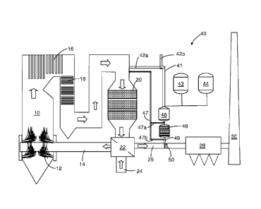
[003] When aqueous urea is heated, a number of chemical reactions, controlled
by
temperature-dependent rate constants, determine how urea is broken down:
NH2-0O2-NH2 --> NH3 HNCO
(Urea) (Ammonia) (Isocyanic Acid)
This reaction can occur at a temperature of 275 F; but the HNCO, unless
hydrolyzed or
maintained very hot can form solid byproducts that can deposit on equipment
and foul
catalysts. The HNCO will be converted as follows:
1
CA 02871405 2019-10-23
WO 2013/162580 PCT/US2012/035237
0
N N
3 HNCO 4
N 0
(Cyanuric Acid)
Cyanuric acid, if formed (and it is likely to form) decomposes at about 7000
F.
The full conversion of urea to ammonia can involve the following reactions,
but not all are
desirable and efforts should be made to moderate or eliminate their negative
effects:
HNCO + H20 NH3 + CO2
(Isocyanic Acid) (Water) (Ammonia) (Carbon Dioxide)
HNCO + NH2-0O2-NH2 4 Biuret
HNCO + Biuret 4 Triuret
Triuret 4 Cyanuric Acid + NH3
3 HNCO 4 Cyanuric Acid
2 NH2-0O2-NH2+ H2C0 4 Methylene Diurea
These reactions are rate dependent as well as dependent on the physical form
of the reactants,
the prevailing temperature, the time in the reactor and the presence or
absence of water
and/or a catalyst.
[004] There are a number of references that discuss converting urea to
ammonia; however, a
review of the art has not enabled the efficient conversion of urea to ammonia
in a form that
could be used for low-temperature operations. Prominent among the prior art
processes are:
(a) wet processes, such as U. S. Patent No. 6,077,491 to Cooper, et al., and
U. S. Patent No.
5,543,123 to Hofmann, et al.; (b) high-temperature processes such as U. S.
Patent No.
7,090,810 to Sun, et al., or U. S. Patent No. 7,682,586 to Harold, et al., and
(c) catalytic
processes such as, for example, U. S. Patent No. 6,878,359, to Mathes, et al.,
and EP 487 886 to
MAN.
[005] Also of note for their lack of teachings enabling efficient production
of ammonia from
urea for low temperature operations is U.S. Pat. No. 5,431,893, to Hug, et al.
To protect the SCR
2
CA 02871405 2019-10-23
WO 2013/162580 PCT/US2012/035237
catalyst from fouling, Hug, et al., proposes bulky equipment capable of
treating all effluent with
urea. Regardless of physical form, urea takes time to break down in hot
exhaust gases and may
cause nozzle plugging at the temperatures most conducive to gasification. This
disclosure
highlights the problems making it a necessity that the urea solution is
maintained at a
temperature below 100 C to prevent hydrolysis in the injection equipment.
They propose the
use of moderate urea pressures when feeding the urea and find it necessary to
have alternative
means to introduce high-pressure air into the feed line when it becomes
plugged. The nozzles
employed by Hug, et al., use auxiliary air to aid dispersion. Also, they
employ dilute solutions
that require significant heating to simply evaporate the water. See also, WO
97/01387 to
Willer, et al.
[006] In European Patent Specification 615,777 A1, there is described an
apparatus that feeds
solid urea into a channel containing exhaust gases, which are said to
hydrolyze the urea in the
presence of a catalyst. For successful operation the disclosure indicates that
it is necessary to
employ compressed air for dispersion of fine solids, means for grinding the
urea into fine solids
and a coating to prevent urea prills from sticking together. The disclosure
notes that if the
inside of the catalyzer and the nozzle tip only were coated with the catalyst,
corrosion and
deposition would occur. The introduction of solid urea into the gas
stream¨possibly depositing
urea on the SCR catalyst ¨ also eliminates control of water to the reactor in
amounts necessary
for efficient hydrolysis, without which HNCO will remain and potentially
harmful byproducts
will be present.
[007] U. S. Patent No. 6,878,359, to Mathes, et al., describes a single stage
process using a
catalyst to gasify urea, but provides no indication that separating
gasification from hydrolysis
into two stages as found highly effective for low-temperature applications by
the invention
herein, would be a useful alternative to a single stage process. We note that
Mathes, et al.,
does not teach high enough initial temperature, temperature maintenance, or
proper droplet
size for a two stage process. Importantly, unless the droplets are small
enough in the first-stage
gasification, the droplets will not release the urea for decomposition early
enough in a short,
3
CA 02871405 2019-10-23
WO 2013/162580 PCT/US2012/035237
e.g., 1 to 10 second, time frame to fully gasify the urea, and the likelihood
of forming
byproducts downstream in the ductwork or the catalyst is increased.
[008] Similar to the above U.S. Pat. No. 6,077,491 to Cooper, et al., is U.S.
Pat. No. 6,146,605
to Spokoyny, where there is described a combined SCR/SNCR process in a staged
process
involving a separate step of hydrolyzing the urea prior to an SCR stage. A
similar process is
disclosed in U.S. Pat. Nos. 5,985,224 and 6,093,380 to Lagana, et al., which
describe a method
and apparatus involving the hydrolysis of urea followed by a separation of a
gas phase from a
liquid hydrolysate phase. In all these processes there is a requirement to
handle a significant
amount of high temperature and high pressure gas and liquid phases containing
ammonia
during and after hydrolysis. This extra processing requires the purchase and
maintenance of
additional equipment, an emergency plan and equipment to handle ammonia
release in case of
process failures, and it would be desirable to have a system which operated
more safely, simply
and efficiently.
[009] It becomes apparent to the skilled worker that the art is not enabling
for low-
temperature effective ammonia from urea generation in an efficient manner. In
the case of air
pollution control, examples of low-temperature processing where it would be
desirable to use
ammonia from a urea source include flue gas conditioning. Here, a small amount
of ammonia is
injected, which differs from selective catalytic reduction systems (SCR) which
operate at
somewhat higher temperatures and depend on ammonia in relatively large
amounts.
[010] While it is noted that EP 0 373 351 to ENEL employs urea to create
ammonia to enhance
the efficiency of the electrostatic precipitator, the urea is supplied as a
mixture of urea, hydrate
lime and water for reducing pollutant materials in the flue gases and does not
produce the
ammonia suitable for low-temperature operations apart from the combustor. Urea
reduces the
NO and hydrate lime reduces the sulfur compounds.
[011] There is a present need for a process, apparatus and system for
efficient supply of
ammonia from urea that does not have low-temperature penalties.
4
CA 02871405 2019-10-23
WO 2013/162580 PCT/US2012/035237
Summary of the Invention
[012] The present invention provides processes, apparatus and systems for
efficient supply of
ammonia from urea that does not have low-temperature penalties.
[013] More particularly, the present invention provides processes, apparatus
and systems for
efficient supply of ammonia from urea to low-temperature processes, such as
flue gas
conditioning, that has all of the advantages of urea gasification without any
penalties caused by
byproduct formation.
[014] When using urea to produce ammonia for low-temperature operations, it Is
important
to utilize two stages for the conversion, the first stage being a thermal
gasification of urea to
produce ammonia and isocyanic acid, followed directly with a second stage
being a controlled
catalyzed hydrolysis reaction wherein the isocyanic acid (HNCO) is hydrolyzed
to ammonia with
carbon dioxide as a byproduct. The process steps will both require careful
temperature control,
and the second stage will require controlling the water to achieve at least a
critical amount of
water without employing so much that the equipment must be too large to
operate efficiently
and create thermal demands in excess of those necessary for effective
reaction.
[015] It is important to run the reaction in a manner to maintain a low
concentration of
intermediate byproducts, e.g., cyanuric acid, in particular, so as to minimize
the chances for
side reactions to produce adverse byproducts, e.g., in cold spots in the
reactors or ducting.
Thus, the relative molar amounts of urea, water and air are important for
successful operation.
[016] In one aspect, a process is provided comprising: (a) in a first stage
thermal reactor,
feeding an aqueous urea solution to a gasification chamber, (b) controlling
feed of urea, water
and heated gases to the first stage reactor in response to demand from a low
temperature
process requiring ammonia; (c) feeding heated gases into the gasification
chamber upstream of
the point for introducing the urea; wherein the inlet temperature of the gases
in the
gasification chamber is within the range of from 700 to 1400 and is sufficient
for time in the
gasification reactor to fully gasify the aqueous urea solution to provide a
first stage gas stream
comprising ammonia and isocyanic acid; (d) withdrawing the first stage gas
stream from the
first stage thermal reactor and maintaining the temperature of first stage gas
stream above 550
CA 02871405 2019-10-23
WO 2013/162580 PCT/US2012/035237
F to a point of introduction into a second stage catalytic reactor; (e)
introducing the first stage
gas stream into a second stage catalytic hydrolysis reactor; (f) monitoring
the amounts of urea
feed, water and heated gases fed into the first stage thermal reactor and
adjusting as necessary
to achieve efficient hydrolysis in the second stage hydrolysis reactor; (g)
maintaining the
temperature of the second stage hydrolysis reactor at a temperature above 370
F; and (h)
withdrawing a second stage gas stream from the second stage reactor responsive
to demand
from a low temperature process requiring ammonia.
[017] In a preferred aspect, the urea is employed as an aqueous solution
having a
concentration of within the range of from 30 to 70% by weight to provide an
overall molar ratio
of water to urea in the system including moisture in the heated air fed to the
first stage reactor
within the range of from 2:1 to 20:1, preferably within the range of from 3:1
to 10:1.
[018] In another aspect, an apparatus is provided comprising: (a) a first
stage thermal reactor,
including a gasification chamber and means for feeding an aqueous urea
solution to the
gasification chamber; (b) means for controlling feed of urea, water and heated
gases to the first
stage reactor in response to demand from a low temperature process requiring
ammonia; (c)
means for feeding heated gases into the gasification chamber upstream of the
point for
introducing the urea; wherein the inlet temperature of the gases in the
gasification chamber is
within the range of from 700 to 1400 F and is sufficient for time in the
gasification reactor to
fully gasify the aqueous urea solution to provide a first stage gas stream
comprising ammonia
and isocyanic acid; (d) means for withdrawing the first stage gas stream from
the first stage
thermal reactor and maintaining the temperature of first stage gas stream
above 500 F to a
point of introduction into a second stage catalytic reactor; (e) means for
introducing the first
stage gas stream into a second stage catalytic hydrolysis reactor; (f) means
for monitoring the
amounts of urea feed, water and heated gases fed into the first stage thermal
reactor and
adjusting as necessary to achieve efficient hydrolysis in the second stage
hydrolysis reactor; (g)
means for maintaining the temperature of the second stage hydrolysis reactor
at a temperature
above 370 OF; and (h) means for withdrawing a second stage gas stream from the
second stage
reactor responsive to demand from a low temperature process requiring ammonia.
6
CA 2871905 2017-04-24
50795-55
[019] Preferably, the method and apparatus are employed in combination with an
electrostatic precipitator to improve operation of the electrostatic
precipitator at temperatures
below 380 F.
[020] Systems employing the process and apparatus as disclosed are also
provided.
[021] Other and preferred aspects of the invention are described below.
Description of the Drawings
[022] The accompanying drawings, which are incorporated in and constitute a
part of this
description, illustrate presently preferred embodiments of the invention, and
together with the
the detailed description of the preferred embodiments given below, serve to
explain the
principles of the invention. As shown throughout the drawings, like reference
numerals
designate like or corresponding parts.
[023] Fig. 1 is a schematic diagram of a combustion installation that takes
advantage of the
present invention employing a preferred embodiment of the process and system
of the
invention.
[024] Fig. 2 is a schematic diagram showing greater detail of aspects of a
system of the
type shown in Fig. 1.
Detailed Description of the Invention
[025] In describing the present invention, reference is made to the
drawings, wherein
there is seen a simplified, preferred embodiment shown schematically in Fig. 1
and Fig. 2.
The drawings and the process they represent will be described briefly below.
[026] The term "urea" is meant to encompass urea in all of its commercial
forms that will
typically consist essentially of urea, containing 95% or more urea by weight.
This relatively pure
form of urea is preferred and has several advantages in the process of the
invention. The urea
is preferably supplied to the process as an aqueous solution at a
concentration of from about
30 to about 70%, with about 45 to about 60% being most preferred.
7
CA 02871405 2019-10-23
WO 2013/162580 PCT/US2012/035237
[027] When urea is gasified by a thermal treatment alone, the reactant gas
will contain
ammonia and it will also contain isocyanic acid (HNCO) which would otherwise
require very
high temperatures to avoid the formation of byproducts in side reactions. A
gasified product at
this stage would not be suitable as such for low-temperature processes. The
invention
addresses this concern and provides a low-cost, low-energy solution.
[028] The gas stream from such thermal processes includes a carrier medium,
such as air or
post-combustion gases, any water in the air, gases or urea solution, and urea
decomposition
products of HNCO and NH3. If this thermal decomposition gas stream approaches
290 F, the
HNCO and NH3 can combine to form a condensable solid (urea) that will be
present as an
aerosol or a deposit on cooler surfaces. The invention controls the relative
amounts of the
components in the thermal decomposition gas stream materials and their
temperature of
handling and passes this gas stream through a second stage catalytic
hydrolysis reactor at a
temperature hotter than the recombination temperature, whereby the HNCO is
efficiently
converted to NH3 and problems of urea or byproduct condensation are
eliminated. This second
stage conversion reduces the risk of recombination at low temperature,
allowing for operation
of the gasification system in applications requiring low temperatures, such as
low temperature
SCRs, ESPs, or for feed into a low-temperature fan.
[029] The addition of a second stage catalyst reactor to a urea
gasification system allows
reagent that has been decomposed in the first stage to be delivered at lower
temperatures
than previously possible (less than approximately 380 F) without the risk of
recombination and
condensation as smoke or deposit on a cool surface. This extends the useful
process
temperature range and permits the use of an ammonia-containing gas feed system
for low-
temperature applications, even cold-side ESP (200 F to 500 F) and low-
temperature SCR
applications for NO, control (300 F to 600 F). In addition, this
configuration makes it possible
to utilize low-temperature blowers or fans (below 600 F) in the post-
gasification gases rather
than being limited to higher temperature fans or blowers (above 600 F) at the
inlet to the
thermal gasification stage. Another advantage of the invention is that there
is no requirement
for high temperatures in ducts used to transport thermally gasified product
streams. Thus,
8
CA 02871405 2019-10-23
WO 2013/162580 PCT/US2012/035237
while the first stage gasification chamber must operate at temperatures
sufficient for urea
decomposition there is no need to maintain such high temperatures in ducts
following the
second stage hydrolysis.
[030] It is also an advantage of the invention that the two-stage reactor
system can be
employed to supply ammonia to a relatively low volume use at low temperatures
and low
concentrations, e.g., to an ESP at concentrations of only 1 to 30 ppm, e.g., 3
to 10 ppm, as the
sole use of ammonia. And, the system can also be configured to supply a second
stream at
higher ammonia concentration, such as for SCR, at higher concentrations, e.g.,
100 to 1000
ppm. The higher volume use can be drawn from either the first-stage or the
second-stage
reactor, as will be described in connection with Fig. 1.
[031] The invention, thus, solves the problem that thermally-gasified urea
is available for
low-volume and relatively low-temperature use without problems of condensation
or forming
deposits on equipment and without the need to maintain the temperature simply
to avoid
deposits. Fig. 1 is a schematic diagram of a combustion installation that
takes advantage of the
present invention to provide a relatively low-temperature ammonia gas stream
obtained by
gasifying aqueous urea in a first stage and then catalytically hydrolyzing
substantially all
isocyanic acid in the stream in a defined second stage. The combustion
installation includes a
combustor 10 having burners that provide thermal heat in combustion zone 12 by
burning fuel
from a source not shown with air supplied by duct work 14. Hot combustion
gases will pass
through the furnace 10 in the direction indicated by the block arrows and the
heat from
combustion is transferred to heat exchangers 16 and 18 prior to passing into a
selective
catalytic reduction (SCR) reactor 20 wherein NO,, created during combustion
can be treated
with ammonia or gasified urea to convert the NO to nitrogen and water.
Alternatively, many
installations will benefit from selective non catalytic reduction (SNCR) using
urea alone at
higher temperatures, e.g., as taught by Epperly, et al., in U. S. Patent No.
5,057,293, without
requiring the reactor 20.
[032] Following SCR reactor 20, the combustion gases will flow through an
air-to-air heat
exchanger 22, which is used to preheat outside air supplied via duct 24 for
delivery to the
9
CA 02871405 2019-10-23
WO 2013/162580 PCT/US2012/035237
combustion zone 12 via line 14. The gases leaving the heat exchanger 22 are
cooled significantly
by the time they are passed through duct work 26 to electrostatic precipitator
(ESP) 28 wherein
particulates are collected prior to passing the gases up stack 30. This is a
highly-simplified
version of actual industrial or utility combustors and effluent treatment
processes, but
illustrates a workable scheme.
[033] The operation of an ESP, such as 28, is often enhanced by flue gas
conditioning. Flue
gas conditioning will typically call for the controlled introduction into the
exhaust gases of small
amounts of a conditioning agent, such as ammonia and/or sulfur trioxide. The
effect is to
reduce the resistivity of the fly ash and to facilitate its collection in an
ESP. It is preferred to
employ ammonia to improve collection even when sulfur trioxide levels are
sufficient to reduce
resistivity. The invention enables the introduction of ammonia into the
relatively cool gases in
duct 26 prior to the ESP unit 28, without either risking the storage of
ammonia gas or fouling
duct work with byproducts of urea gasification. Fig. 1 shows an arrangement of
apparatus
(shown generally as 40) capable of providing a supply of ammonia.
[034] The ammonia supply system 40 is shown to include process air supply
41, a urea
supply 43, water supply 44, first stage thermal gasification chamber 46 and
second stage
catalytic hydrolysis reactor 48. The resulting ammonia is supplied to duct 26
via line 49 and
ammonia injection grid 50, or the like. The air for the ammonia supply system
40 can be either
a side stream of flue gas from line 42a or alternate air from ambient via line
42b or from
preheater 22, or elsewhere, from a line not shown. The amount of process air,
its temperature
and moisture content are important to the efficiency of the process and will
be monitored for
process control.
[035] As noted above, is an advantage of the invention that the two-stage
reactor system
can be employed to supply ammonia to a relatively low volume use at low
temperatures and
low concentrations, e.g., to an ESP at concentrations of only 1 to 30 ppm,
e.g., 3 to 10 ppm, as
the sole use of ammonia. In this case, the ammonia would be supplied via line
49, as shown.
And, the system can also be configured to supply a second stream at higher
ammonia
concentration, such as for SCR, at higher concentrations, e.g., 100 to 1000
ppm, via lines 47a or
CA 02871405 2019-10-23
WO 2013/162580 PCT/US2012/035237
47b. Each of these arrangements has a number of advantages, such as for the
arrangement
wherein line 47a is employed to feed the high-volume use from the first-stage
reactor 46.
[036] Fig. 2 shows the ammonia supply system 40 in greater detail, yet
still schematically.
The numbering for Fig. 2 employs the numbers from Fig. 1, where applicable and
continues
¨
with additional features, such as controller 60 and associated sensors ( )
and valves
which are illustrated by the symbols shown here parenthetically. Incoming
process air line 41 is
shown to include a damper 41a which is controllable by controller 60 and
associated exemplary
control lines (which may be hard wired or wireless) shown in dotted lines.
Fig. 2 also shows
water feed line 44a, without showing the source.
[037] It is believed important to utilize two stages of operation, the first
being a thermal
gasification of urea to produce ammonia and isocyanic acid, followed directly
with a second
stage being a controlled catalyzed hydrolysis reaction wherein the isocyanic
acid is hydrolyzed
to ammonia with carbon dioxide as a byproduct. The urea is preferably supplied
from 43 to the
first stage of the process as an aqueous solution at a concentration of from
about 30 to about
70%, with about 45 to about 60% being most preferred. The relative molar
amounts of urea,
water and air are important for successful operation.
[038] The catalyst is preferably of the type used in SCR systems, typical
of which are those
with vanadium contents of from about 1 to about 4 %. Other catalysts can be
employed. The
catalyst is desirably of a size to provide space velocities of 1000 to 30,000
hr-', e.g., from about
2500 to about 7500 hr'. The catalyst structure will preferably be monolithic
with continuous
channels causing little pressure drop across the depth or length of the
catalyst and have a pitch
of from 1 to 10 mm to accommodate this purpose. Catalysts based on vanadium,
titanium and
tungsten, typically as oxides, will be effective. In one embodiment a TiO2
catalyst with a pitch of
about 4 mm and containing a vanadium content of between 1 and 2 % is
effective.
[039] The process steps will both require careful temperature control, and
the second
stage will require at least a critical amount of water without employing so
much that the
11
CA 02871405 2019-10-23
WO 2013/162580 PCT/US2012/035237
equipment must be too large to operate efficiently and create thermal demands
in excess of
those necessary for effective reaction.
[040] It has also been found important to run the reaction in a manner to
maintain a low
concentration of intermediate products, e.g., isocyanic acid, in particular,
so as to minimize the
chances for side reactions to produce adverse byproducts, e.g., in cold spots
in the reactors or
ducting.
[041] The molar ratios of air to water to urea will most effectively be
from about 500:20:1
to about 1000:5:1. The molar ratios of water to urea will most effectively be
from about 2:1 to
20:1, preferably within the range of from 6:1 to 10:1.
[042] The use of two separate, sequential stages to the conversion of urea
to a useful gas
stream containing ammonia enables the gasification to occur completely at a
high temperature
and then a full conversion of HNC to ammonia in near quantitative amounts,
e.g., at least
90%, and preferably at least 95%, with 99% or more being a suitable target.
When employing
the high-temperature gasification in one stage including a hydrolysis
catalyst, as done by some
prior art procedures, there is a chance for processing anomalies due to the
hydrolysis of HNCO
at the same time as gasification. And, unless temperatures are carefully
controlled and cold
spots fully eliminated, side reactions are likely to occur. U. S. Patent No.
6,878,359, to Mathes,
et al., describes a single stage process using a catalyst to gasify urea, but
provides no indication
that separating gasification from hydrolysis into two stages as found highly
effective for low-
temperature applications by the invention herein, would be a useful
alternative to a single
stage process. We note that Mathes, et al., does not teach high enough initial
temperature,
temperature maintenance, or proper droplet size for a two stage process.
Importantly, unless
the droplets are small enough in the first-stage gasification, the droplets
will not release the
urea for decomposition early enough in a short, e.g., 1 to 10 second, time
frame to fully gasify
the urea, and the likelihood of forming byproducts downstream in the ductwork
or the catalyst
is increased. Temperature, reactants, droplet size, and heating time must all
work together to
achieve the correct reaction kinetics for full urea gasification without solid
byproduct
production.
12
CA 02871405 2019-10-23
WO 2013/162580 PCT/US2012/035237
[043] At the high-end temperature of 200 C mentioned for the single stage
process of
Mathes, et al., for example, the gases would be too cool to fully gasify the
urea and maintain it
in a gaseous state initially. Moreover, the gases would be further cooled by
the water in the
aqueous urea ¨the water being necessary in significant amounts to assure the
required
hydrolysis. Indeed, Mathes, et al., at column 8, lines 54+, states
"...byproducts which are also
formed in the process, such as for example melamine ..., are deposited while
they are still in the
preparation reactor 10 and do not enter the exhaust gas line 1". Thus, it
appears Mathes, et al.,
cannot guarantee complete gasification in a single stage with the hydrolysis
catalyst.
[044] In the first, gasification, stage of the process of the invention, it
is important to
employ suitably high temperatures, obtain a small droplet size of urea in the
chamber and
avoid the presence of cold spots. Droplet sizes are preferably controlled to
be less than 500 um,
typically from 20 to 200 um, as measured by laser techniques. Residence time
in the chamber is
necessarily short, e.g., on the order of from 1 to 10 seconds, typically from
2 to 6 seconds.
[045] The amount of water present for hydrolysis will include that added by
both the urea
solution, including any dilution water, and the system air, and must be
sufficient to fully
hydrolyze the HNCO in the second stage of the process. Because water is
characterized by an
enthalpy of vaporization, 40.65 kiimol, more than five times the energy
required to heat the
same quantity of water from 0 C to 100 C, any excess water should be
avoided, but this has
not been a concern of the prior art.
[046] The heated gases entering stage one gasification chamber 46 via inlet
41 will gasify
the urea, principally to ammonia and isocyanic acid (HNCO), leaving
essentially no liquids or
solids. The gases entering gasification chamber 46, will preferably be within
the range of from
700 to 1400 F at inlet and will be sufficient to fully gasify the aqueous
urea solution for their
time in the gasification reactor, to provide a first stage gas stream
comprising ammonia and
isocyanic acid. The first stage gas stream is withdrawn from the first stage
thermal reactor and
maintaining the temperature of first stage gas stream above at least 400 F,
e.g., at least 500 F
to a point of introduction into the second stage catalytic reactor where the
first stage gas
13
CA 02871405 2019-10-23
WO 2013/162580 PCT/US2012/035237
stream will be passed into a second stage catalytic hydrolysis reactor at a
temperature of from
350 to 600 F.
[047] The gases are preferably heated to greater than 800 F prior to being
introduced into
the chamber 46 at a temperature where they should remain above at least 600
F. Entering gas
temperatures of from 850 *to 1400 F can be employed effectively. Supplemental
heat can be
supplied to the chamber as necessary. And, preferably, the chamber 46 will be
well insulated to
aid in temperature maintenance. The temperature of the gases and the residence
time prior to
exit from the chamber 46 will be effective to achieve full gasification. The
entry temperature
and temperature maintenance in chamber 46 should be high enough also to
maintain an exit
temperature of at least about 400 F, e.g., at least 450 F and preferably at
least 500 F.
[048] If necessary, heating can be employed following gasification and as
being transferred
into hydrolysis reactor 48, but it is preferred that the gases entering
chamber 46 will be hot
enough to provide an exiting gas meeting the above criteria. Temperatures
within hydrolysis
reactor 48 are desirably within the range of from 350 to 600 F, and
preferably within the range
of from 400 to 500 F.
[049] Systems employing the process and apparatus combine the disclosed
features and
incorporate details as necessary for a wide variety of industrial
applications.
[050] The above description is for the purpose of teaching the person of
ordinary skill in
the art how to practice the invention. It is not intended to detail all of
those obvious
modifications and variations, which will become apparent to the skilled worker
upon reading
the description. It is intended, however, that all such obvious modifications
and variations be
included within the scope of the invention which is defined by the following
claims. The claims
are meant to cover the claimed components and steps in any sequence which is
effective to
meet the objectives there intended, unless the context specifically indicates
the contrary.
14