Note: Descriptions are shown in the official language in which they were submitted.
CA 02871680 2014-10-21
WO 2013/163388 PCT/US2013/038156
1
CORRUGATED AND APERTURED WEB
FIELD OF THE INVENTION
The present invention is directed to apertured web materials. More
specifically, the webs
comprise alternating ridges and grooves, wherein apertures are located in the
grooves.
BACKGROUND OF THE INVENTION
Various methods and apparatuses for aperturing, deforming, and/or stretching
webs are
disclosed in the patent literature. With an aperturing method such as rotary
knife aperturing, it is
difficult to produce a web having closely-spaced apertures wherein the
apertures have desirable
widths in the cross-machine direction ("CD"). In order to space aperture rows
close together,
activation teeth may be provided which have a very small included angle.
However, this
approach poses a problem because apertures are produced which do not have
sufficient aperture
width in the CD, even at high engagement depths (the interference of an
activation tooth roll with
a mating ring roll). The resultant apertures are often elongated in the
machine direction¨leading
to a slit-like appearance, low open area, and potential stress concentrations
which cause in-use
tearing. Creating slit-like, low-open-area apertures is particularly
problematic as tougher and
more tear-resistant webs are utilized. Rounded or tapered hot-pin aperturing
is common, but has
the drawback of requiring greater registration precision for the mating rolls,
and it typically
results in greater aperture spacing. Rounded or tapered hot-pin aperturing is
typically run at
lower linear speeds.
Post ring-rolling an apertured web to stretch it is possible, but can result
in alternating
rows of aperture sizes since apertures cannot be lined up with the subsequent
ring roll stretching
process. It is difficult to align features in the cross direction with later
processes due to variable
spreading of the substrate. Post ring-rolling can also significantly weaken
the web, making it
more prone to tearing.
It is desirable to produce a web having discrete, closely-spaced apertures
wherein the
apertures have larger CD widths than previously possible. A need exists for an
apertured web
which is stronger in the cross-machine direction so it doesn't easily tear in
the cross-machine
direction. A need exists for a method of producing an apertured web having
larger, wider, more
open apertures. A need also exists for apparatuses that will allow a web to be
apertured with the
apertures having desired, larger-widths in the cross-machine direction.
CA 02871680 2014-10-21
WO 2013/163388 PCT/US2013/038156
2
There are many known processes for creating a web with ridges and grooves, for
example
ring rolling. There are also many know processes for creating a web with
apertures, for example,
hot pin aperturing. However, it is difficult to produce a corrugated web
having alternating ridges
and grooves which are registered to a specific aperture pattern. Processes
exist for micro-
aperturing followed by ring-rolling; however, this results in flattened webs
with no corrugation.
A web with ridges and grooves (flat strips) may be formed via air-jetting or
water jetting on a
patterned belt. However, air-jetting or water jetting are much slower
processes and requires more
energy than the invention described herein. In addition, the ridges are not
hollow and can retain
more fluid.
It is desirable to produce a web having alternating ridges and grooves wherein
apertures
are located in specific positions in the web, for instance, in the grooves or
in the ridges. A need
exists for an apertured web which comprises a registered corrugation pattern.
These are all goals of the present invention; embodiments described herein may
achieve
various combinations of these goals. A particular embodiment may, but need
not, embody every
goal.
SUMMARY OF THE INVENTION
The present inventions are directed to apertured and/or corrugated web
materials and
apparatuses and methods for aperturing a web to create such materials. Such
materials can be
provided as members of products such as absorbent articles (such as topsheets,
backsheets,
acquisition layers, liquid handling layers, and absorbent cores), packaging
(such as flow wrap,
shrink wrap, and polybags), wipes, facial tissue, toilet tissue, paper towels,
and the like. There
are numerous non-limiting embodiments of the present invention.
The present inventions relate to a web comprising: alternating ridges and
grooves; and
alternating regions of lower basis weight and higher basis weight; wherein the
higher basis
weight regions are located in the ridges and grooves; wherein the lower basis
weight regions are
located in the sidewalls between the ridges and grooves; and wherein the
higher basis weight
regions located in the grooves comprise apertures.
The present inventions further relate to a web comprising alternating ridges
and grooves
with sidewalls therebetween, wherein the ridges are hollow and have tops and
the grooves are
hollow and have bottoms, wherein the grooves comprise apertures, and wherein
the web is a
nonwoven web.
The present inventions still further relate to a web comprising alternating
ridges and
grooves with sidewalls therebetween, wherein the ridges are hollow and have
tops and the
CA 02871680 2015-05-13
3
grooves are hollow and have bottoms, wherein the grooves comprise apertures,
and
wherein the web is a micro-textured film or flat film.
The present invention further relates to a web comprising alternating ridges
and
grooves with sidewalls therebetween, wherein the ridges are hollow and have
tops and the
grooves are hollow and have bottoms, wherein the grooves comprise apertures,
wherein
the web is a nonwoven web comprising fibers having diameters, and wherein the
average
fiber diameter at the tops of the ridges and the average fiber diameter at the
bottoms of
the grooves is greater than the average fiber diameter at the sidewalls.
The present invention still further relates to a web comprising alternating
ridges
and grooves with sidewalls therebetween, wherein the ridges are hollow and
have tops
and the grooves are hollow and have bottoms, wherein the grooves comprise
apertures,
wherein the web comprises a thickness, wherein the web thickness at the tops
of the
ridges and the web thickness at the bottoms of the grooves is greater than the
web
thickness at the sidewalls, and wherein the web is a micro-textured film or
flat film,
preferably wherein the film is a micro-textured film comprising stretched
areas and
unstretched areas, wherein the stretched areas have micro-texture properties
differing
from the unstretched areas, and wherein the micro-textured properties are
selected from
the group consisting of open area, size, orientation, and combinations
thereof.
BRIEF DESCRIPTION OF THE DRAWINGS
The accompanying drawings are included to provide a further understanding of
the
present inventions. The drawings illustrate the present inventions described
herein, and together
with the description, serve to explain the claimed subject matter.
FIG. 1 is a perspective view of a prior art pair of ring rolls for deforming a
web.
FIG. 2A is a perspective view of a prior art pair of rolls¨a rotary knife
aperturing (or
"RKA") roll and a ring roll¨for aperturing a web.
FIG. 2B is a side view of the pair of prior art rolls shown in FIG. 2A.
FIG. 2C is an enlarged side view of the nip between the rolls shown in FIG.
2A.
FIG. 2D is a top view of an exemplary prior art web that can be formed by
using the rolls
shown in FIG. 2A.
FIG. 3A is a perspective view of a pair of rolls for use in the apparatuses
and processes
described herein, in which one roll is a staggered "raised ridge" RKA roll and
the other roll is a
ring roll.
CA 02871680 2015-05-13
3a
FIG. 3B is an enlarged side view, of the nip between the rolls shown in FIG.
3A.
FIG. 4A is a perspective view of a portion of the surface of an exemplary
raised ridge
RKA roll.
FIG. 4B is a perspective view of a portion of the surface of an exemplary ring
roll.
FIG. 4C is a perspective view of a portion of the surface of an exemplary
raised ridge
SELF roll.
FIG. 5A is a perspective view of a portion of the surface of another exemplary
raised
ridge RICA roll.
FIG. 5B is a side view of the tooth arrangement shown in FIG. 5A.
FIG, 5C is an end view of the tooth arrangement shown in FIG. 5A.
FIG. 5D is a top view of the tooth arrangement shown in FIG. 5A.
FIG. 5E is a section view along the line D-D of the tooth arrangement shown in
FIG. 5B.
FIG. 5F is a section view along the line E-E of the tooth arrangement shown in
FIG. 5B.
FIG. 6A is a front view of a first exemplary set of teeth, wherein the teeth
are tapered and
truncated.
FIG. 6B is a front view of a second exemplary set of teeth, wherein the teeth
are tapered
and semi-truncated.
CA 02871680 2014-10-21
WO 2013/163388 PCT/US2013/038156
4
FIG. 6C is a front view of a second exemplary set of teeth, wherein the teeth
are tapered
and non-truncated.
FIG. 7 is a schematic of a tooth pattern wherein the end facet angle 7 and the
ridge
finishing can be accomplished in a single helical machining step.
FIG. 8 is an enlarged side view of a portion of the surface of an alternative
raised ridge
RKA roll.
FIG. 9A is a top view of one example of a web that can be formed by using a
variation of
the rolls in FIG. 3A.
FIG. 9B is an enlarged view of one of the apertures shown in FIG. 9A.
FIG. 10 is a side view of another embodiment of an apparatus for aperturing a
web
wherein the three rolls are in a planetary arrangement.
FIG. 11 is a top view of a 25 gsm PE film web (film is stretched/flattened out
to show
high and low basis weight regions).
FIG. 12 is a top view of a 60 gsm PP nonwoven web (nonwoven is
stretched/flattened out
to show high and low basis weight regions).
FIG. 13 is a cross-section view of the web shown in FIG. 12.
FIG. 14 is side perspective view of another nonwoven web.
FIG. 15 is a top perspective view of a nonwoven web.
FIG. 16 is a cross-sectional view of a film web.
FIGS. 17, 18A, and 18B are top views of apertured film webs described in
Example 1.
FIG. 19A is a top perspective view of an apertured nonwoven web as described
in
Example 2.
FIG. 19B is a bottom perspective view of the web of FIG. 19A.
DETAILED DESCRIPTION
The following text sets forth a broad description of numerous different
embodiments of
the present invention. The description is to be construed as exemplary only
and does not
describe every possible embodiment since describing every possible embodiment
would be
impractical, if not impossible. And it will be understood that any feature,
characteristic,
component, composition, ingredient, product, step or methodology described
herein can be
deleted, combined with or substituted for, in whole or part, any other
feature, characteristic,
component, composition, ingredient, product, step or methodology described
herein. Numerous
alternative embodiments could be implemented, using either current technology
or technology
CA 02871680 2016-05-05
developed after the filing date of this patent, which would still fall within
the scope of the claims.
It should also be understood that, unless a term is expressly defined in this
specification
using the sentence "As used herein, the term __________________________ ' is
hereby defined to mean..." or a similar
5 sentence,
there is no intent to limit the meaning of that term, either expressly or by
implication,
beyond its plain or ordinary meaning, and such term should not be interpreted
to be limited in
scope based on any statement made in any section of this patent (other than
the language of the
claims). No term is intended to be essential to the present invention unless
so stated. To the
extent that any term recited in the claims at the end of this patent is
referred to in this patent in a
manner consistent with a single meaning, that is done for sake of clarity only
so as to not confuse
the reader, and it is not intended that such a claim term be limited, by
implication or otherwise, to
that single meaning.
The present invention enables an apertured web which is stronger in the cross-
machine
direction so it doesn't easily tear in the cross-machine direction. A process
for producing an
apertured web having discrete, closely-spaced apertures with a desired, larger
width in the cross-
machine direction is described. The process can also produce a structure with
alternating ridges
and grooves, with apertures contained in the grooves. An apparatus that will
allow a web to be
apertured with desired, discrete, closely-spaced, larger-width apertures in
the cross-machine
direction is also described.
As used herein, the term "absorbent article" includes disposable articles such
as sanitary
napkins, panty liners, tampons, interlabial devices, vvouncl dressings,
diapers, adult incontinence
articles, wipes, and the like. Still further, the absorbent members produced
by the processes and
apparatuses disclosed herein can find utility in other webs such as scouring
pads, dry-mop pads
(such as SWIFFERO pads), and the like. At least some of such absorbent
articles arc intended
for the absorption of body liquids, such as menses or blood, vaginal
discharges, urine, and feces.
Wipes may be used to absorb body liquids, or may be used for other purposes,
such as for
cleaning surfaces. Various absorbent articles described above will typically
comprise a liquid
pervious topsheet, a liquid impervious backsheet joined to the topsheet, and
an absorbent core
between the topsheet and backsheet.
As used herein, the term "absorbent member" refers to the components of the
absorbent
article that typically provide one or more liquid handling functionality,
e.g., liquid acquisition,
CA 02871680 2014-10-21
WO 2013/163388 PCT/US2013/038156
6
liquid distribution, liquid transportation, liquid storage, etc. If the
absorbent member comprises
an absorbent core component, the absorbent member can comprise the entire
absorbent core or
only a portion of the absorbent core.
As used herein, the term "aperture" refers to a hole. The apertures can either
be punched
cleanly through the web so that the material surrounding the aperture lies in
the same plane as the
web prior to the formation of the aperture (a "two dimensional" aperture), or
holes formed in
which at least some of the material surrounding the opening is pushed out of
the plane of the
web. In the latter case, the apertures may resemble a "three dimensional"
aperture. Three
dimensional apertures generally maintain more open area under an applied load.
As used herein,
the term "apertured" refers to a web comprising a plurality of apertures.
As used herein, the term "component" of an absorbent article refers to an
individual
constituent of an absorbent article, such as a topsheet, acquisition layer,
liquid handling layer,
absorbent core or layers of absorbent cores, backsheets, and barriers such as
barrier layers and
barrier cuffs.
As used herein, the terms "corrugated" or "corrugation" mean a three-
dimensional web
topography comprising a plurality of generally parallel alternating ridges and
grooves, wherein
the ridges and grooves undulate about an axis X (drawn horizontally through a
cross-section of
the web). The ridges and grooves may undulate equally on either side of the
axis, or may be
lopsided.
As used herein, the term "cross-machine direction", "cross direction", or "CD"
means the
path that is perpendicular to the machine direction in the plane of the web.
As used herein, the term "deformable material" is a material which is capable
of changing
its shape or density in response to applied stresses or strains.
As used herein, the term "depth of engagement" ("DOE") means a degree of
meshing
between two rolls. The distance is measured from the outermost tip of the
tooth or ridges on a
first roll to the outermost tip of the tooth or ridges on a second roll. The
terms "meshing" or
"intermeshing," as used herein, refer to arrangements when the teeth/ridges on
one of the rolls
extends toward the surface of the other roll and at least some of the
teeth/ridges have portions
that extend between and below an imaginary plane drawn though the tips of the
teeth/ridges on
the surface of the other roll.
As used herein, the term "discrete" means distinct or unconnected. When the
term
"discrete" is used relative to teeth on a raised ridge roll, it is meant that
the distal (or radially
outwardmost) ends of the teeth are distinct or unconnected in all directions,
including in the
CA 02871680 2014-10-21
WO 2013/163388 PCT/US2013/038156
7
machine and cross-machine directions (even though bases of the teeth may be
formed into the
same surface of a roll, for example). For example, the ridges on a ring roll
are not considered to
be discrete.
As used herein, the term "disposable" describes absorbent articles and other
products
which are not intended to be laundered or otherwise restored or reused as an
absorbent article or
product (i.e., they are intended to be discarded after use and, preferably, to
be recycled,
composted or otherwise disposed of in an environmentally compatible manner).
As used herein, the term "hollow" describes ridges and grooves present in a
web made by
the apparatuses and processes described herein; the ridges and grooves
comprise open spaces
having no web material present. For instance, a web comprises ridges, grooves,
and an X axis
drawn horizontally through a cross-section of the web; the area above the X
axis but under the
top of the ridge is hollow, or comprises a hollow area. Likewise, the area
below the X axis but
above the bottom of the groove is hollow, or comprises a hollow area.
As used herein, the term "machine direction" or "MD" means the path that
material, such
as a web, follows through a manufacturing process.
As used herein, the term "macroscopic" refers to structural features or
elements that are
readily visible and distinctly discernible to a human having 20/20 vision when
the perpendicular
distance between the viewer's eye and the web is about 12 inches (30 cm).
Conversely, as used
herein, the term "microscopic" refers to such features that are not readily
visible and distinctly
discernible under such conditions.
As used herein, the terms "ring roll" or "ring rolling" refer to a process
using deformation
members comprising counter rotating rolls, intermeshing belts, or intermeshing
plates containing
at least portions of continuous ridges and grooves where intermeshing ridges
(or projections) and
grooves (or recesses) of deformation members engage and stretch a web
interposed
therebetween. Unless otherwise stated, ring rolls alone do not aperture webs.
For ring rolling,
the deformation members can be arranged to stretch the web in the cross
machine direction, the
machine direction, or in a helical direction/at an angle to the CD or MD
depending on the
orientation of the ridges and grooves. Examples described herein which pertain
to one direction
are to be understood as enabling the non-described directions.
As used herein, the term "rotary knife aperturing" (RKA) refers to a process
and
apparatus using intermeshing deformation members, or rolls, wherein one or
more roll comprises
a plurality of teeth. The teeth can be sharpened to cut through as well as
deform a web to
CA 02871680 2014-10-21
WO 2013/163388 PCT/US2013/038156
8
produce an apertured web, or in some cases, a three-dimensionally apertured
web, as disclosed in
US 2005/0064136A1 and US 2006/0087053A1.
The terms "SELF" or "SELF'ing", refer to Procter & Gamble technology in which
SELF
stands for Structural Elastic Like Film. Processes, apparatus, and patterns
produced via SELF
are illustrated and described in U.S. Pat. Nos. 5,518,801; 5,691,035;
5,723,087; 5,891,544;
5,916,663; 6,027,483; and 7,527,615 B2. While the process was originally
developed using tooth
geometries that would deform a polymer film without producing apertures, other
tooth
geometries have been developed that are more conducive to forming tufts (in
the case of a
nonwoven) or tents (in the case of a film) with apertures on the leading and
trailing ends. A
process using SELF'ing to form tufts with apertures in a nonwoven web is
disclosed in U.S.
Patent No. 7,682,686 B2.
As used herein, the term "teeth" refers to any elements on the surface of a
roll that are
capable of aperturing a web.
I. Apertured Web Materials
While the term "apertured web materials" is utilized herein, the object is to
create
components, such as absorbent members (or non-absorbent members), for
absorbent articles from
such apertured web materials. In such cases, the apertured web materials will
be cut into
individual components for absorbent articles (such as topsheets, backsheets,
acquisition layers,
absorbent cores). In the case of webs used in absorbent articles, such new
structures may include
those that provide improved properties (such as improved softness, fluid
handling, or other
properties) in a predetermined portion of the web. These apertured webs can be
cut to form
various other components of products for packaging (e.g., flow wrap, shrink
wrap, and
polybags), wipes, facial tissue, toilet tissue, paper towels, and the like.
Discrete, closely-spaced apertures having a larger width in the CD direction
can be
provided in webs and the components formed therefrom which are not possible to
produce with
current methods and tooling. The new apertures comprise greater open areas and
lower aspect
ratios (aperture length:aperture width) which (in the case of a film) result
in increased web
strength, as compared to equivalent open area apertures achievable via the
prior art (see FIG.
2D).
In addition, webs created with this new technology have a unique, more
textured
appearance. The textured webs may comprise alternating ridges and grooves,
wherein apertures
are intentionally contained within the grooves. In the case of the apertured
webs being used for
absorbent articles, the web may offer better fluid acquisition, breathability,
or separation from the
CA 02871680 2014-10-21
WO 2013/163388 PCT/US2013/038156
9
body, thus promoting a drier, cleaner feeling. For example, in a sanitary
napkin, apertures
located in grooves help channel and transfer fluid from a topsheet to lower
absorbent members.
Not only do the apertures provide these benefits, but any corrugation present
in the final web
may additionally support these benefits. For instance, the corrugation offers
at least partial non-
contact with the body, which improves breathability, produces a drier feel,
and promotes less
contact with a wet/soiled surface which may irritate skin or feel
uncomfortable. In the case of a
sanitary napkin, corrugations may channel fluid in a longitudinal direction
along the sanitary
napkin and keep fluid away from the side edges of the sanitary napkin.
The web (or "precursor web") that will be apertured can comprise any suitable
deformable material, such as a woven, nonwoven, film, flat film, micro-
textured film,
combination, or laminate of any of the foregoing materials. As used herein,
the term "nonwoven
web" refers to a web having a structure of individual fibers or threads which
are interlaid, but not
in a repeating pattern as in a woven or knitted fabric, which do not typically
have randomly
oriented fibers. Nonwoven webs may or may not comprise thermal bond points.
This may
include paper substrates, such as tissue, drylap, liner board, filter paper,
and combinations
thereof. Nonwoven webs or fabrics have been formed from many processes, such
as, for
example, meltblowing, spunbonding, hydroentangling, airlaid, wetlaid, through-
air-dried paper
making processes, and bonded carded web processes, including carded thermal
bonding.
Depending on the forming process, the nonwoven web may or may not comprise
thermal bond
points. Film materials can be single layer, multi-layer, embossed, or micro-
textured. The woven,
nonwoven, film, combination, or laminate can be made of any suitable materials
including, but
not limited to natural materials, synthetic materials, and combinations
thereof. Suitable natural
materials include, but are not limited to cellulose, cotton linters, bagasse,
wool fibers, silk fibers,
etc. In some embodiments, the web materials may be substantially free of
cellulose, and/or
exclude paper materials. In other embodiments, the processes described herein
may be
performed on cellulose-containing precursor materials. Suitable synthetic
materials include, but
are not limited to rayon and polymeric materials. Suitable polymeric materials
include, but are
not limited to: polyethylene (PE) (e.g., linear low density polyethylene
(LLDPE), low density
polyethylene (LDPE), high density polyethylene (HDPE), or the like),
polyester, polyethylene
terephthalate (PET), and polypropylene (PP). Any of the materials described
above may
comprise post-consumer recycled material. The apparatuses described herein
work with a wide
range of materials and lower cost materials. For instance, one can use
commodity spunbond
nonwovens, multiple layers with different chemical & mechanical properties and
control the
CA 02871680 2014-10-21
WO 2013/163388 PCT/US2013/038156
degree of inter-mixing of the two or more layers, nonwovens with various fiber
formulations &
formations; or films. In addition, this apparatus can run directly on-line
(and not lose loft due to
roll compression/storage).
Various polymers can be used to produce the webs of interest. Potential
materials include
5 biopolymers made from non-petroleum sources such as bio-derived
polyethylene (bio-PE), bio-
derived polypropylene (bio-PP), bio-derived polyethylene terephthalate (bio-
PET), and bio-
derived poly(ethylene-2,5-furandicarboxylate) (bio-PEF). These materials can
be partially or
completely derived from at least one renewable resource where a renewable
resource refers to a
natural resource that can be replenished within a 100 year time frame.
Renewable resources
10 include plants, animals, fish, bacteria, fungi, and forestry products
and may be naturally
occurring, hybrids, or genetically engineered organisms. Natural resources
such as crude oil,
coal, and peat which take longer than 100 years to form are not considered to
be renewable
resources. Other polymers derived from non-petroleum sources include starch-
based polymers
and cellulosics. Additionally, recycled resins such as post-consumer regrind r-
HDPE, r-LLDPE,
r-LDPE, r-PET, r-PEF, or r-PP can be used at 100% or blended with various
resins. Polymers
derived from renewable resources and recycled resins could be used on their
own, or blended into
petroleum-based polymers at varying levels in order to control the cost.
Sources and methods of
making polymers from non-petroleum sources can be found in US 8,063,064 B1 and
US
2011/0319849 Al.
The present inventions are directed to apertured web materials and apparatuses
and
processes for aperturing and stretching a web to create such materials that
overcome one or more
of the shortcomings of the prior art. Stretching, or growing, a web is
beneficial because it
enables lower costs via overall basis weight reduction of the web. By
aperturing and then
stretching in the same process step, a wider, more preferred aperture is
created in the web
material. Here, aperturing and stretching occurs in a single unit op in a
registered manner so that
the stretching occurs while the tooth is still penetrating the material and,
therefore, doesn't allow
the aperture to collapse when stretched. The additional stretching step not
only allows an
aperture to be wider, but also has the potential to create a web with a
corrugated appearance.
Such an aperturing-then-stretching combination must be exactly registered. If
aperturing and
stretching were in separate steps, like the prior art, the apertures wouldn't
be registered with the
stretching ring roll and the apertures may close up. Also, webs created with
this new process are
softer and more drapable from stretching (loosened and/or thinned fibers
and/or films). Thinner
webs are generally desirable because less fluid can be retained by the web.
This is important
CA 02871680 2014-10-21
WO 2013/163388 PCT/US2013/038156
11
when a web is used as a topsheet for an absorbent article, as there is less
saturation in the
top sheet.
In one non-limiting embodiment, the apertured web material comprises a web
having
discrete apertures formed therein. The web has a first surface and a second
surface opposite the
first surface. The web comprises substantially non-apertured regions, or
lands, which surround a
plurality of discrete apertures.
The apertures are densely packed within a relatively small area. For example,
the center-
to-center spacing in any direction between apertures may be less than or equal
to about 20mm,
lOmm, 5mm, 3mm, 2mm, lmm, or 0.5mm. The total number of apertures in an area
that
measures 1 square inch (645mm2) may be greater than or equal to 4, 25, 100,
250, 500,1000, or
3000. The number of apertures in a one inch square area can be determined by
marking a square
area on the material that measures 1 inch (25.4mm) by 1 inch with a fine tip
pen or marker and
counting the number of first, second, third, etc. apertures that lie fully or
partially within and on
the boundary of the 1 inch square. A low power microscope or other magnifying
aid can be used
to aid visibility of the apertures in the material if needed. The apertures
may be of any suitable
configuration.
The apertures may be of any suitable size. Typically, the apertures will be
macroscopic.
The plan view area of the apertures may be greater than or equal to about
0.5mm2, 1mm2, 5 mm2,
10mm2, or 15mm2. The processes described herein can also be used to create
apertures that are
microscopic which have plan view areas less than 0.5mm2.
In addition to apertures, the web may comprise alternating ridges and grooves,
wherein
the apertures are located in the grooves. The ridges may extend continuously
or form
discontinuous ridges in the deformed region of the web. The grooves may extend
continuously
with apertures spaced at regular intervals within the grooves. Note that if
the web is turned
upside-down, the grooves will become the ridges and the ridges will become
grooves, and the
apertures will now be in located in the ridges. The apertures may be two-
dimensional or three-
dimensional, depending on the process and material parameters. In the case of
three-dimensional
apertures, the base of the apertures will extend in the opposite direction of
the ridges. The sides
of the ridges and sides of the grooves are more oriented in the z-direction
than the tops of the
ridges and bottoms of the grooves.
In the case of a film, the sides of the ridges and the sides of the grooves
may be thinner
and have a lower basis weight than the tops of the ridges and the bottoms of
the grooves as a
result of the stretching process. This results in a web with alternating
regions of higher caliper
CA 02871680 2014-10-21
WO 2013/163388 PCT/US2013/038156
12
and basis weight, and regions of lower caliper and lower basis weight, with
the higher caliper and
basis weight regions being located in the tops of the ridges and bottoms of
the grooves, and the
regions with lower caliper and basis weight located in the sidewalls in-
between. Alternating
basis weight provides thinned/flexible areas for comfort and maintained
thickness for strength.
In the case of a nonwoven, the basis weight is also decreased in the stretched
areas, again
resulting in a web with alternating regions of higher and lower basis weight,
with the higher basis
weight regions located in the tops of the ridges and bottoms of the grooves,
and the lower basis
weight regions located in the sidewalls in-between. In the case of a nonwoven,
the web thickness
may not decrease in the stretched areas because the fibers may detangle and
move away from
each other. However, the thickness of some of the individual fibers may
decrease as a result of
the stretching, resulting in fiber diameters that range from 40% to 80% of the
original fiber
diameter. The average fiber diameter at the tops of the ridges and the average
fiber diameter at
the bottoms of the grooves may be greater than the average fiber diameter at
the sidewalls.
While in tooth lock at the ridges and grooves, the base web thickness does not
vary significantly.
Although the web is textured, the thickness of the web locally at the ridges
and grooves does not
vary significantly as the ridges and grooves are not filled, rather they form
hollow areas, because
they have been deformed out of plane. Hollow ridges are not able to retain as
much fluid as
filled ridges, which can provide dryness benefits when used as a topsheet in
an absorbent article.
As a result of the stretching, the web permanently elongates in the direction
of the stretching.
Suitably, the web thickness in the stretched areas is from 20% to 80% of the
original web
thickness.
II. Prior Art Apparatuses for Deforming Web Materials
Prior art approaches are not suitable for creating apertures having wider
dimensions in the
cross-machine direction¨particularly with tough or tear-resistant films.
Therefore, it is desirable
to design a process that enables aperturing and then stretching in the same
process step (i.e.,
within the same nip and while the aperturing teeth are still penetrating the
web) to obtain
apertures in the web material which have larger dimensions in the cross-
machine direction than
are obtainable with the prior art approaches. Prior art approaches are also
not suitable for
creating webs having alternating ridges and grooves, with apertures located in
the grooves, using
high speed aperturing and stretching means such as that described here.
FIG. 1 shows a first prior art apparatus 10 in which the rolls 12 and 14 are
referred to
herein as ring rolls. The rolls 12, 14, as in the case of the rolls in the
other apparatuses shown
and described herein, are carried on respective rotatable shafts having their
axes A of rotation
CA 02871680 2014-10-21
WO 2013/163388 PCT/US2013/038156
13
disposed in a parallel relationship. In all of the embodiments described
herein, the rolls are non-
contacting, and axially-driven. In this embodiment, the surfaces of the rolls
have a plurality of
alternating grooves 16 and ridges 18 extending around the circumference of the
rolls. In other
embodiments, the ridges and grooves may extend parallel to the axes A of the
rolls. One or more
such rolls can be used in the various embodiments of the apparatuses described
herein.
In the embodiment shown in FIG. 1, and the various other embodiments described
herein,
the rolls mesh or at least partially intermesh. As shown in FIG. 1, the rolls
typically rotate in
opposite directions (that is, the rolls are counter-rotating). This is also
the case for the other
embodiments described herein.
FIGS. 2A ¨ 2C show a second prior art apparatus 20 in which the top roll 22 is
a Rotary
Knife Aperturing (or "RKA") roll and the bottom roll 24 is referred to herein
as a ring roll. The
apparatus comprises a pair of counter-rotating, intermeshing rolls, wherein
the top roll 22
comprises pyramidal teeth 30 having four or more sides, the sides being
substantially triangular
and being tapered from a base towards a tip, and the bottom roll 24 comprises
circumferentially-
extending grooves 26 and ridges 28. The teeth 30 are arranged in spaced apart
circumferential
rows with grooves therebetween. The teeth 30 extend from the top roll 22 at
the base, and the
base of the tooth has a cross-sectional length dimension greater than a cross-
sectional width
dimension. Typically, apertures are formed in a web material as the teeth 30
on the RKA roll 22
intermesh with grooves 26 on the ring roll 24. With respect to tooth height,
tooth spacing, pitch,
depth of engagement, and other processing parameters, RKA and the RKA
apparatus can be the
same as described in U.S. Patent Application Publication No. US 2006/0087053
Al.
The RKA roll 22 shown in FIG. 2A comprises a staggered (vs. standard) tooth
pattern.
As used herein, the term "staggered" means that adjacent teeth do not align in
rows in the CD.
As used herein, the term "standard" means that adjacent teeth align in rows in
the CD and thus
are non-staggered. As shown in FIG. 2C, the rolls 22 and 24 are aligned in the
cross-machine
direction such that the teeth 30 on the RKA roll 22 align with the grooves 26
on the ring roll 24.
As the teeth 30 penetrate the web, the ridges on the mating ring roll 28
support the web such that
the teeth 30 can penetrate the web and simultaneously form apertures in the
opposite direction.
FIG. 2D shows a top view of an exemplary prior art web 34 that can be made by
an apparatus
like that shown in FIGS. 2A ¨ 2C. The resultant web 34 comprises lands 36
surrounding
apertures 38. Apertures 38 formed by prior art apparatuses like that of FIGS.
2A ¨ 2C comprise
a length in the machine direction L and a width in the cross-machine direction
W. These
CA 02871680 2014-10-21
WO 2013/163388 PCT/US2013/038156
14
apertures are typically slit-like, having widths W much smaller than lengths
L, particularly with
tougher and more recoverable webs.
III. Apparatuses and Processes Employing a Roll with Teeth Extending from a
Raised Ridge to
Aperture Web Materials
In general, the apparatus comprises two intermeshing forming structures that
form a nip
therebetween. Forming structures may comprise rollers, plates, belts, sleeves,
other structures
capable of imparting a texture to a web, or combinations thereof. The first
forming structure
comprises a plurality of first ridges and first grooves on the surface of the
forming structure,
wherein said first ridges have a top surface and said first grooves have a
bottom surface. The
first forming structure further comprises a plurality of spaced-apart teeth
extending outwardly
from the top surface of said first ridges, each tooth being capable of forming
an aperture, wherein
the top surface of said first ridge is located between the tips of said teeth
and the bottom surface
of said first grooves. A second forming structure comprises a plurality of
continuous second
ridges and second grooves.
More specifically, the apparatus comprises a single pair of counter-rotating,
intermeshing
rolls that form a single nip N therebetween. Although the apparatuses will be
described herein
for convenience primarily in terms of rolls, it should be understood that the
description will be
applicable to any suitable apparatus that may comprise any suitable type(s) of
forming members,
including, but not limited to: a pair of rolls; pairs of plates; conveyors
with pucks (or small
plates); belts; or combinations thereof. The first roll and second roll each
comprise a surface
106, 108 which comprises a plurality of circumferentially-extending ridges and
grooves.
Alternatively, the ridges and grooves could extend in a direction parallel to
the axis of the roll, as
long as it is mated to a roll that has ridges and grooves extending in the
same direction. The first
roll additionally comprises a plurality of spaced-apart teeth, wherein the
teeth extend outwardly
from the top surfaces of the ridges. This creates a "raised ridge." The ridges
of the second roll
extend toward the axis of the first roll to a depth beyond the top of at least
some of the ridges on
the first roll. In this manner, the initial engagement of the tooth creates an
aperture, which is then
stretched in the cross-machine direction when the engagement proceeds to a
depth below the
raised ridge. By first aperturing, and then stretching in one process step,
while the tooth is still
penetrating the web, the resulting apertures have a larger width in the cross-
machine direction
than would apertures produced by a standard toothed roll as described above
and shown in FIGS.
2A ¨ 2D.
CA 02871680 2014-10-21
WO 2013/163388 PCT/US2013/038156
The apertures of the present invention comprise lower aspect ratios (aperture
length: aperture width) and much higher open areas than the apertures of the
prior art, particularly
when utilized with tougher films, e.g., those containing high levels of LLDPE.
The new tooth
geometry facilitates a high open area at lower tooling temperatures, enabling
the formation of
5 apertures in webs which could not be apertured with traditional tooth
geometry. The new tooling
geometry provides the ability to aperture webs at lower heats (e.g., between
35 and 70 degrees
Celsius) or even at ambient temperatures rather than requiring the heating of
the apparatus.
Further, there are minimal to lower costs involved to create this tooling vs.
prior tooling since,
inter alia, less metal is removed. Accordingly, room temperature precursor
webs may be used.
10 In one embodiment, the precursor web and intermeshing rolls are not
heated. Or, overall
preheated webs may be used. Or, zoned preheating of webs may enable apertures
in some zones
and bubbles in others. Preheating may be accomplished by wrapping the RKA roll
prior to
engagement (with varying wrap times prior to engagement possible) or, by
wrapping the ring roll
prior to engagement. Likewise, heated or non-heated tooling may be used.
Suitably, the web is
15 heated by wrapping the RKA roll heated to 50-200 degC, or 50-100 degC.
The RKA roll and
ring roll may be driven at identical speeds of the outermost surface or there
may be a speed
differential between the two rolls.
The following figures show non-limiting examples of specific roll arrangements
and the
apertured web materials that can be formed thereby. These apparatuses are able
to utilize a
single nip, and run at higher processing speeds, with no heat in some cases,
and at less expense
than prior art methods for aperturing and stretching (e.g., since it is a
simple mechanical process
¨ just two intermeshing rolls).
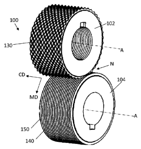
FIGS. 3A and 3B show an exemplary apparatus 100 of the present invention which
comprises a single pair of counter-rotating, intermeshing rolls 102, 104 that
form a single nip N
therebetween. The first (top) roll 102 is a variation of the RKA roll shown in
FIG. 2A. This
particular variation will be referred to herein as a "raised-ridge RKA roll."
The second (bottom)
roll 104 in the apparatus 100 shown in FIGS. 3A and 3B is a ring roll.
As shown in FIG. 4A, the first roll 102 comprises a plurality of grooves 110
and ridges
120 and a plurality of staggered, spaced-apart teeth 130 extending outwardly
from the top surface
122 of the ridges 120. The configuration of the roll 104 is such that the top
surface 122 of the
ridges 120 is disposed between the tips 134 of the teeth 130 and the bottom
surface 112 of the
grooves 110, directionally relative to the axis A of the roll. As shown in
FIG. 4B, the second roll
104 comprises a plurality of grooves 140 and ridges 150. The grooves 140 have
a bottom surface
CA 02871680 2014-10-21
WO 2013/163388 PCT/US2013/038156
16
142 and the ridges 150 have a top surface 152. Here, the distance between the
top surfaces 152
of the ridges 150 and the bottom surfaces 142 of the grooves 140 is
substantially the same around
the circumference of the roll. FIG. 4C is an alternative second roll 104B in
the form of a raised
ridge staggered CD SELF roll. The configuration of the roll 104B is such that
the top surface
122 of the ridges 120 is disposed between the tips 134 of the teeth 130 and
the bottom surface
112 of the grooves 110, directionally relative to the axis A of the roll.
Turning back to FIGS. 3A
and 3B, the teeth 130 and ridges 120 of the first roll 102 extend toward the
axis A of the second
roll 104, intermeshing to a depth beyond the top 152 of at least some of the
ridges 150 on the
second roll 104.
Teeth suitable for this process must be conducive to aperturing webs. The
teeth on the
rolls may have any suitable configuration. A given tooth can have the same
plan view length and
width dimensions (such as a tooth with a circular or square shaped plan view).
Alternatively, the
tooth may have a length that is greater than its width (such as a tooth with a
rectangular plan
view), in which case, the tooth may have any suitable aspect ratio of its
length to its width.
Suitable configurations for the teeth include, but are not limited to: teeth
having a triangular-
shaped side view; square or rectangular-shaped side view; columnar shaped;
pyramid-shaped;
teeth having plan view configurations including circular, oval, hour-glass
shaped, star shaped,
polygonal, and the like; and combinations thereof. Polygonal shapes include,
but are not limited
to rectangular, triangular, pentagonal, hexagonal, or trapezoidal. The side-
walls of the teeth may
taper at a constant angle from the base to the tip, or they may change angles.
The teeth may taper
towards a single point at the tooth tip, like that shown in FIG. 4A. The teeth
can have tips that
are rounded, flat or form a sharp point. Alternatively, the teeth may taper
towards a multi-point,
elongated tooth tip, like the SELF teeth shown in FIG. 4C. However, the tip of
the tooth must
form a sharp vertex with at least one of the vertical walls of the tooth (for
example, the vertical
walls on the leading and trailing ends of the teeth as shown in FIG. 4C), so
the teeth aperture or
puncture the web. In the case of the teeth shown in FIG. 4C, each tooth may
form 2 apertures,
one at the leading edge and one at the trailing edge of each tooth.
In one exemplary embodiment shown in FIGS. 5A-F, the first roll 102 comprises
a
plurality of pyramid-shaped teeth 130 extending outwardly from the top surface
122 of the ridges
120. FIG. 5A is a perspective view of a portion of the surface of another
exemplary raised ridge
RKA roll. FIG. 5B is a side view, FIG. 5C is an end view, and FIG. 5D is a top
view of the tooth
arrangement shown in FIG. 5A. FIG. 5E is a section view along the line D-D of
the tooth
arrangement shown in FIG. 5B. FIG. 5F is a section view along the line E-E of
the tooth
CA 02871680 2014-10-21
WO 2013/163388 PCT/US2013/038156
17
arrangement shown in FIG. 5B. The tooth cross-sectional area At shown in FIG.
5E is less than
the tooth cross-sectional area Atb shown in FIG. 5F. The sides (e.g., 130a ¨
130f shown in FIG.
5E) are substantially triangular and tapered at a constant angle from a tip
134 to a base 132. The
number of sides may be four (e.g., FIG. 4A), six (e.g., FIGS. 5A ¨ 6C), or
another number less
than or equal to twelve. The teeth 130 are arranged in spaced-apart
circumferential rows with
grooves 110 therebetween. The MD tip-to-tip tooth spacing SmD is from 0.4mm to
15mm (or
from 3mm to 8mm). The CD pitch P is from 0.4mm to lOmm (or from lmm to 3mm).
The teeth
have an included angle a of from 30 to 90 degrees (or from 45 to 65 degrees),
a side wall angle 13
on the long side of the teeth (e.g., 130c, 1300 of from 3 to 15 degrees, and
an end-facet included
angle 7 of the leading and trailing edges of the teeth (e.g., the angle
between sides 130a and 130b
or the angle between sides 130d and 130e) of from 45 to 120 degrees (or from
60 to 90 degrees).
In some cases, the MD and CD tooth spacing, staggering, and included end-facet
angle 7 are
chosen when the teeth are created by helical grinding.
There are different ways to finish the portion 136 where the teeth 130 and
ridge surface
122 meet, for instance, truncated (FIG. 6A), wherein the taper on each side is
cut off by a plane;
semi-truncated (FIG. 6B), wherein the taper on at least one side is cut off by
an arc; or non-
truncated (FIG. 6C), wherein the taper on each side is not cut off in any
manner. The teeth 130
shown in FIG. 6A taper from the tip 134 towards the base 132 and have a
truncated lower portion
136. The taper and/or truncation may occur at different degrees. A truncated
taper on a tooth
makes the tooth easier to manufacture. In this case, referring to FIG. 7, the
end facet angle 7 and
the ridge finishing can be accomplished in a single helical machining step as
is well known in
fabrication practices, by rotating the tooling in the circumferential
direction Dc while
simultaneously advancing the machining in the axial direction of the tooling.
The end facet of
the tooth 130 will be created following the machining path M. For a tooth
stagger Ts, the
included end facet angle 7 is thus created as 2 * Arctan (CD Tooth Pitch "P" /
Tooth Stagger
"Ts").
The top surfaces 122 of the ridge between the teeth 130 may be finished in
different
manners. For instance, the surface 122 may be radiused or non-radiused. A
radiused surface
would protect the web from tears during forming, particularly in the case of a
film, while a non-
radiused surface (such as the surface 122 shown in FIGS. 6A ¨ 6C) may be more
cost effective.
The configuration of the raised ridge RKA roll 102 is such that the top
surface 122 of the
ridges 120 are disposed between the tips 134 of the teeth 130 and the bottom
surface 112 of the
grooves 110, directionally relative to the axis A of the roll 102. The tooth
height ht is defined as
CA 02871680 2014-10-21
WO 2013/163388 PCT/US2013/038156
18
the distance between the tip 134 of the tooth 130 and the bottom surface 112
of the grooves 110.
The tooth height ht is from lmm to 12mm, or from 2mm to 8mm, or from 3mm to
6mm. The
ridge height hr is at least 20%, typically from 20% to 95%, of the tooth
height. The cross-cut
depth dee is defined as the distance between the tip 134 of the tooth 130 and
the top surface 122
of the ridge 120. In this embodiment, the distance between the tip 134 of the
tooth 130 and the
top surface 122 of the ridge 120 is substantially the same around the
circumference of the roll.
The cross-cut depth dee depends on the amount of deformation that is required
to form the
apertures. For example, the cross-cut depth dee may be within the range of 0.2
mm to 9 mm, or
from 1.0mm to 4.0mm or from 2.0mm to 3.5mm. A smaller cross-cut depth dee (at
the same
DOE) creates a more open aperture. The depth of engagement of the pair of
rolls 102, 104 must
be greater than the cross-cut depth dee. Suitably, the depth of engagement is
at least 0.1mm
greater or 0.3mm greater than the cross-cut depth. The DOE at the nip N is
from 0.5mm to
lOmm, or from 3mm to 7mm, or from 3mm to 4mm.
The ridge height hr is defined as the distance between the top surface 122 of
the ridge 120
and the bottom surface 112 of the grooves 110. In some embodiments, such as
shown in FIGS.
3B and 4A, the first roll 102 comprises a cross-direction width, and the
distance between the top
surfaces 122 of the ridges 120 and the bottom surfaces 112 of the grooves 110
is substantially the
same around the circumference and across the CD width of the roll 102. Or, the
distance
between the top surfaces of the first ridges and the bottom surfaces of the
second grooves can
vary around the circumference or across the CD width of the first roll.
Various alternative
embodiments of the raised ridge rolls are possible. For example, as shown on
roll 162 in FIG. 8,
the height of the ridges hr may vary between at least some of the teeth 168.
The ridge height hr
depends on the amount of deformation that is required to form the desired
apertures. The top
surface 166 of at least one ridge 164 between a pair of teeth 168 will have a
height hrt that is at
least 10%, 20%, or 30% greater than the height 11,2 of another ridge 164
between another pair of
pair of teeth 168. This roll 162 could be used in a process such as that shown
in FIG. 3A in
place of the raised-ridge RKA roll 102. The second roll may be a ring roll
with ridges of
different heights in either the circumferential or axial directions.
FIG. 9A shows an example of a web 170 which can be made by the apparatus shown
in
FIG. 3A: an RKA raised-ridge roll with a staggered tooth pattern for the upper
roll 102 and a ring
roll for the lower roll 104. The rolls 102 and 104 are aligned in the cross-
machine direction such
that the teeth 130 on the first roll 102 align with the grooves 140 on the
second roll 104. As the
teeth 130 on the first roll 102 penetrate the web 170, the ridges 120 between
the teeth 130 on the
CA 02871680 2014-10-21
WO 2013/163388 PCT/US2013/038156
19
RKA raised ridge roll 102 support the web 170 such that the ridges 150 on the
second roll 104
can stretch the web 170 in the cross-machine direction.
The web in its initial state can be thought of as being relatively flat, and
comprised
entirely of non-apertured regions. The web 170 has a first surface 170A and a
second surface
170B. When the web is fed in the machine direction into the nip N between the
rolls (e.g., those
shown in FIG. 3A), the web is: (i) apertured by the teeth 130 of the first
roll 102 to form a
plurality of spaced apart apertures 172; and (ii) stretched by the ridges 120
of the first roll 102 to
stretch the apertures 172 in the cross-machine direction. As shown in the FIG.
9A web top view,
the result is an apertured web 170 comprising apertures 172 and lands 174
surrounding the
apertures 172. The apertures 172 may be pushed out of the plane of the web
160 in one
direction (downward as viewed in FIG. 9A) thus the aperture 172 may have a
height Ha. The
apertures 172 are aligned in rows in the MD and the CD. FIG. 9B shows an
enlarged top view of
a single aperture 172. The apertures 172 comprise a length in the machine
direction La and a
width in the cross-machine direction Wa. The apertures will preferably have a
length-divided-by-
width aspect ratio AR of from 1 to 4, or from 1.25 to 3, or from 1.5 to 2.5,
or from 1.6 to 2.3.
The apertures 172 further comprise an individual open area Aa and a perimeter
surrounding the
open area Pa. The apertured web comprises a total open area of from 5% to 25%,
or from 9% to
21%, or from 10% to 16%, or from 14% to 20% of the total web area. The
apertured film
comprises a tear, or tensile, strength (per 25.4mm) in the cross-machine
direction in the range of
1.5 N to 5 N, 2 N to 4 N, 2.5 N to 4 N, 2.5 N to 3.5 N, or 2.7 N to 3.9 N. The
apertured
nonwoven comprises a tensile strength (per 25.4mm) in the cross-machine
direction in the range
of 2 N to 20 N, or higher. In one example, a web comprises a machine direction
orientation and
a cross-machine direction orientation, wherein the apertures comprise a length
in the machine
direction and a width in the cross-machine direction, and wherein a plurality
of apertures
comprise a length-divided-by-width aspect ratio of 1 to 4.
In some embodiments, the stretching step described above not only increases
the CD
width of the aperture, but also creates alternating ridges and grooves, where
the apertures are
located in the grooves. The portion of the web that is in contact with the
ridges on the two rolls
friction locks on the tops of the ridges and is not stretched, while the web
in-between the ridges is
stretched out of plane. The portion of the web that is stretched out of plane
becomes more
oriented in the z-direction. As a result, a web with ridges and grooves may be
formed, with the
apertures located in the grooves. Note that if the web is turned upside-down,
the grooves will
become the ridges and the ridges will become grooves, and the apertures will
now be in located
CA 02871680 2014-10-21
WO 2013/163388 PCT/US2013/038156
in the ridgesThe fibers at the tops of the ridges and the fibers at the
bottoms of the grooves may
be more oriented in an X-Y plane than are the fibers at the sidewalls.
In the case of a film, the web is thinned and the basis weight is decreased in
the stretched
regions, while the web thickness and basis weight are maintained in the
regions of the web that
5 are friction locked on the ridges of the rolls. This results in a web
with alternating regions of
higher and lower caliper, and alternating regions of higher and lower basis
weight, with the
higher caliper and higher basis weight regions being located in the tops of
the ridges and bottoms
of the grooves, and the regions with lower caliper and lower basis weight
located in the sidewalls
in-between. FIG. 11 is a top view of a 25 gsm PE film web 210 (film is
stretched/flattened out to
10 show high basis weight regions 212 and low basis weight regions 214).
Web 210 further shows
ridges R, grooves G, and sidewalls S. Apertures 216 are present in the grooves
G. As apparent,
the high basis weight regions 212 are located in the ridges R and grooves G,
whereas the low
basis weight regions 214 are located in the sidewalls S.
In the case of a nonwoven, the basis weight is also decreased in the stretched
areas, again
15 resulting in a web with alternating regions of higher and lower basis
weight, with the higher basis
weight regions located in the tops of the ridges and bottoms of the grooves,
and the lower basis
weight regions located in the sidewalls in-between. FIG. 12 is a top view of a
60 gsm
polypropylene nonwoven web 220 (nonwoven is stretched/flattened out to show
high basis
weight regions 222, and low basis weight regions 224). Web 220 further shows
ridges R,
20 grooves G, and sidewalls S. Apertures 226 are present in the grooves G.
Thermal or fusion bond
points 228 may be present in various locations on the web 220. As apparent,
the high basis
weight regions 222 are located in the ridges R and grooves G, whereas the low
basis weight
regions 224 are located in the sidewalls S. In the case of a nonwoven, the web
thickness may not
decrease in the stretched regions because the fibers may detangle and move
away from each
other. However, the thickness of some of the individual fibers may decrease as
a result of the
stretching. Note that the "regions" of the web used to characterize basis
weight exclude the
apertures themselves.
As a result of the stretching, the web permanently elongates in the direction
of the
stretching. If the web remains in its corrugated state, the majority of the
increased web width is
taken up by the ridges and grooves that are formed in the web. Alternatively,
tension could be
applied to expand the web, which would result in a decrease in the height and
frequency of the
ridges and grooves, and decrease the web's overall basis weight. If desired,
the web could be
expanded such that ridges and grooves no longer exist, and the web is back to
its flattened state.
CA 02871680 2014-10-21
WO 2013/163388 PCT/US2013/038156
21
This deformation process may stretch or grow a web by 10%, by 15%, by 20%, by
25%, or more
in the CD. The amount of permanent stretch and degree of formation of the
ridges and grooves
depends on the tooling geometry, process conditions and the properties of the
materials.
Typically this process will permanently stretch or grow a non-woven web
material further than a
__ film material. For example, a web may grow from 165mm to 190mm in the CD.
Suitably, the
web has an initial web basis weight and the lower basis weight regions have a
basis weight which
is lower than the initial web basis weight.
FIG. 13 is a cross-section view of the web 220 shown in FIG. 12 showing ridges
R,
grooves G, and axis X drawn horizontally through a cross-section of the web;
the area above the
__ X axis but under the top of the ridge is hollow, or comprises a hollow area
HA. Likewise, the
area below the X axis but above the bottom of the groove is hollow, or
comprises a hollow area
HA. Suitably, the web thickness at the tops of the ridges and the web
thickness at the bottoms of
the grooves are similar. The web thickness at the tops of the ridges and the
web thickness at the
bottoms of the grooves may be similar to the web thickness at the sidewalls.
By similar, it is
__ meant that the thicknesses are within about 60% of one another. Or, the web
thickness at the tops
of the ridges and the web thickness at the bottoms of the grooves is greater
than the web
thickness at the sidewalls. FIG. 14 is side perspective view of another
nonwoven web 230
having ridges 232, grooves 234, and sidewalls 236. FIG. 15 is a top
perspective view of 28 gsm
polyethylene/polypropylene bico nonwoven web 240 comprising ridges 242 and
grooves 244 and
__ apertures 246 wherein the aperture width Wa is greater than the ridge width
Wr. FIG. 16 is a
cross-sectional view of a film web 250 showing greater thinning at the
sidewall 256 than at the
top of the ridge 252 or bottom of the groove 254.
The processes of interest herein may also utilize multiple deformation steps
in order to
more gently deform the material or to impart a greater amount of permanent
deformation. Such
__ multiple deformation steps can be carried out by any suitable apparatuses
described in U.S.
Patent Application Serial No. 13/094,195 to Lake, et al. Suitably, at least
the first roll or the
second roll also forms a nip with one or more additional rolls to thereby
further stretch or deform
the web. In one arrangement 200, as shown in FIG. 10, a ring roll 202 is mated
to a raised-ridge
roll 204 which is in turn mated to another ring roll 206 such that the rolls
are in a planetary or
__ satellite configuration. Processes utilizing multiple deformation steps may
also be carried out on
nested apparatuses having a relatively small number of rolls in a nested
arrangement, or such
apparatuses as the hybrid, closed loop, and shared bank with any suitable
number of rolls in order
to carry out the desired deformation.
CA 02871680 2014-10-21
WO 2013/163388 PCT/US2013/038156
22
Numerous alternative embodiments of the apertured web materials and processes
of
making the same are possible. For example, web materials can be provided which
have different
zones (including deformed zones and/or undeformed zones) across their surface
with different
features therein. The zones may by at least one feature selected from the
group consisting of:
ridge height, ridge spacing, aperture size, fiber diameter, film thickness, or
combinations thereof.
In one embodiment, an apertured web material can be provided which has zones
of apertures, and
in some cases, ridges and grooves. Webs disclosed herein may contain zones
with different sizes
of apertures and/or different sizes and frequencies of ridges and grooves. The
web can comprise
one or more layers. In another embodiment, the film is a micro-textured film
comprising
stretched areas and unstretched areas, wherein the stretched areas have micro-
texture properties
differing from the unstretched areas, and wherein the micro-textured
properties are selected from
the group consisting of open area, size, orientation, and combinations
thereof. Webs made by the
processes and apparatuses described herein may comprise ridges that run
discontinuously across
a deformed zone, or, ridges that run continuously across a deformed zone. To
create such
apertured web materials, the ring roll used may comprise zones of ridges and
grooves. Or, the
ring roll can have zones where the ridges are different heights, thereby
creating differing depth of
engagement (DOE), differing depth below the raised ridge, and thus apertures
with differing
widths and open areas. Alternatively or in addition, the raised ridge roll may
comprise different
zones, wherein ridge heights are different in different zones.
EXAMPLES
Example 1
In one non-limiting example for making apertures in a polymer film, like the
web 300
shown in FIG. 17 (comprising micro-apertures 312 and macro-apertures 314), an
apparatus can
be used that comprises a 1.5mm pitch raised ridge RKA roll intermeshed with a
1.5mm pitch ring
roll at 3.8mm depth of engagement. The raised ridge RKA roll has teeth that
are oriented so the
long direction runs in the MD. The teeth are arranged in a staggered pattern
as shown in FIG.
5A. The teeth have a pyramidal shape with 6 sides that taper from the base to
a sharp point at
the tip, and have a height ht of 4.7mm. The teeth have an included angle (a
from FIG. 5B) of 62
degrees, a side wall angle on the long side of the tooth of about 6 degrees
([2. from FIG. 5C), and
an end facet included angle of 90 degrees (y from FIG. 5E). The ridges that
span between the
teeth on the RKA roll are non-radiused and form a flat surface. The teeth are
finished at the ridge
in a semi-truncated format as shown in FIG. 6B. The ridges and grooves extend
circumferentially around the ring roll.
CA 02871680 2014-10-21
WO 2013/163388 PCT/US2013/038156
23
There are two different sections of teeth on the roll, which are exhibited to
demonstrate
the benefits of the raised ridge and referred to individually as "Section A"
and "Section B".
Section A has a MD tooth spacing SmD tip to tip of 4.9mm, a cross cut depth
(dcc in FIG. 6A) of
3.6mm and resultant ridge height (hR in FIG. 6A) of 1.1mm. Section B has a MD
tooth spacing
SmD tip to tip of 3.7mm, a cross-cut depth dec of 2.7mm, and resultant ridge
height hr of 2.0mm.
The mating ring roll is 1.5mm pitch with a height of 4.8mm, a tip radius of
0.12mm, and
a side wall angle of about 4 degrees. Both rolls have a diameter of about
205mm, and are heated
to 80 degC. The RKA roll and ring roll are aligned in the CD such that the
clearances on either
side of the teeth are about equal.
The precursor web is a micro-apertured polymer film at a basis weight of 26
g/m2, with a
blend of LLDPE and LDPE, obtained from RKW-Group, Germany. LLDPE comprises
about
60% of the film composition, LDPE about 30%, and inerts and fillers such as
TiO2 and the
carrier resins thereof the remaining 10%. The micro-apertures are 55 mesh
(apertures per inch in
orthogonal directions), arranged in an equilateral triangle pattern with
center-to-center spacings
of about 462 microns. Aperture diameters are 175-200 microns and tapered cone
heights of
approximately 120 microns.
The precursor web is pre-wrapped on the ring roll prior to passing between the
intermeshing rolls at a linear web speed of 480 meters/min. The micro-
apertured cones side of
the film is placed facing the RKA roll. A depth of engagement of 3.8mm is
used. The resultant
films are shown in low magnification in FIGS. 18A and 18B. The open areas (%
of film area
with an open aperture), aperture lengths, and aperture widths of said films
are measured with a
vision system, such as can be purchased from Cognex Corporation of Natik,
Massachusetts,
under the IN-SIGHT tradename. The open area, length and width comparison of
apertures from
Section A (FIG. 18A) vs. Section B (FIG. 18B) are shown in the table below.
FIGS. 18A and
18B depict film webs 320, 340 having micro-apertures 322, 342 and apertures
324, 344.
Cross -Cut Raised Ridge Open Aperture
Aperture
Depth Height Area Length Width
dcc (mm) hR (mm) % (mm) (mm)
Section A 3.6 1.1 5.76 1.20 0.52
Section B 2.7 2.0 14.63 1.40 0.63
Example 2
In one non-limiting example for making a corrugated web having apertures in
the
grooves, an apparatus can be used that comprises a 2.0mm pitch raised ridge
RKA roll
intermeshed with a 2.0mm pitch ring roll at 6.3mm depth of engagement. The
raised ridge RKA
CA 02871680 2014-10-21
WO 2013/163388 PCT/US2013/038156
24
roll has teeth that are oriented so the long direction runs in the MD, and the
ridges and grooves
extend circumferentially around the ring roll. The teeth are arranged in a
staggered pattern as
shown in FIG. 5A. The teeth have a pyramidal shape with 4 sides that taper
from the base to a
sharp point at the tip, and have a height ht of 6.9mm. The teeth have an
included angle (a from
FIG. 5B) of 57 degrees and a side wall angle on the long side of the tooth of
about 5 degrees ([2.
from FIG. 5C). The ridges that span between the teeth on the RKA roll are not
rounded and form
a flat surface. The teeth are finished at the ridge in the non-truncated
format as shown in FIG.
6C. The teeth have an MD tooth spacing SmD tip to tip of 8.0mm, a cross cut
depth (do, in Figure
6A) of 3.7mm and resultant ridge height (hR in Figure 6A) of 3.2mm.
The mating ring roll is 2.0mm pitch with a height of 6.9mm, a tip radius of
0.12mm, and
a side wall angle of about 4 degrees. Both rolls have a diameter of about
142mm. The RKA roll
and ring roll are aligned in the CD such that the clearances on either side of
the teeth are about
equal.
The first precursor web is a polymer film at a basis weight of 25 g/m2, with a
blend of
LLDPE and LDPE, obtained from Clopay Plastics Co. in Ohio. The precursor web
is pre-
wrapped on the ring roll prior to passing between the intermeshing rolls at a
linear web speed of
meters/min. The resultant corrugated, apertured film is shown in FIG. 11 (film
is
stretched/flattened out to show high and low basis weight regions). Images
were taken at low
magnification using an optical microscope, such as can be purchased from
Allasso Industries,
20 using red LED back lighting.
The second precursor web is a thermally bonded polypropylene nonwoven at a
basis
weight of 60 g/m2, obtained from Fiberweb in France. The precursor web is pre-
wrapped on the
ring roll prior to passing between the intermeshing rolls at a linear web
speed of 20 meters/min.
The resultant corrugated, apertured nonwoven is shown in FIG. 12 (top view;
web is
stretched/flattened out to show high and low basis weight regions), FIG. 13
(cross-section view),
FIG. 19A (raised-ridge RKA side), and FIG. 19B (ring roll side). Images were
taken at low
magnification using an optical microscope, such as can be purchased from
Allasso Industries.
The web 400 in FIGS. 19A and 19B comprises alternating ridges 402 and grooves
404; apertures
406 are present in the grooves 404.
The dimensions and values disclosed herein are not to be understood as being
strictly
limited to the exact numerical values recited. Instead, unless otherwise
specified, each such
dimension is intended to mean both the recited value and a functionally
equivalent range
surrounding that value. For example, a dimension disclosed as "40mm" is
intended to mean
CA 02871680 2016-05-05
?5
"about 40mm." Furthermore, the numerical ranges recited herein include each
discrete numerical
value as well as any other narrower range which lies within the range. It
should be understood
that every maximum numerical limitation given throughout this specification
includes every
lower numerical limitation, as if such lower numerical limitations were
expressly written herein.
Every minimum numerical limitation given throughout this specification will
include every
higher numerical limitation, as if such higher numerical limitations were
expressly written herein.
Every numerical range given throughout this specification will include every
narrower numerical
range that falls within such broader numerical range, as if such narrower
numerical ranges were
all expressly written herein.
The citation of any document is not to be construed as an admission that it is
prior art
with respect to the present invention. To the extent that any meaning or
definition of a term in
this written document conflicts with any meaning or definition of the term in
a document cited
herein, the meaning or definition assigned to the term in this written
document shall govern.
While particular embodiments of the present invention have been illustrated
and
described, the scope of the claims should not be limited by the preferred
embodiments set forth
in the examples and drawings, but should be given the broadest interpretation
consistent with the
description as a whole.