Note: Descriptions are shown in the official language in which they were submitted.
CA 02871836 2014-11-21
REDUCING WHEEL FORCES ON A FIELD SURFACE
This disclosure relates to the field of agricultural implements and in
particular provides a
system and method for reducing wheel forces exerted on agricultural field
surfaces.
BACKGROUND
A typical towed agricultural implement has a frame supported on frame wheels
with a
hitch extending forward from the frame for connection to a tractor for towing
in an
operating travel direction, and a plurality of ground engaging tools mounted
on the frame.
The frame wheels support the frame in an orientation parallel to the soil
surface such that
each ground engaging toolpenetrates the soil to the same depth. In order to
allow larger
modern agricultural implements to follow varying ground contours the implement
frame
will typically include a plurality of wing frames connected at horizontal
pivot axes
oriented parallel to the operating travel direction. The frame wheels must be
located and
configured to support each wing frame in an orientation horizontal to the
surface of the
soil under the wing frame. The frame wheels may be configured to move up and
down
with respect to the frame to adjust working depth, however during operation
the frame
wheels are fixed in a working position relative to the frame to maintain the
frame in the
desired orientation such that the depth of penetration of the ground engaging
tools is
maintained at the desired depth.
In order to perform a typical agricultural operation in a field, the ground
engaging tools
must be laterally spaced equally across the width of the implement such that
the paths of
the tools in the ground are equally spaced. For example in an air seeder, seed
row
spacing is selected to optimize crop yields, and the lateral spacing of the
furrow openers
must be equal to the desired row spacing across the entire width of the frame.
Similarly
in a cultivating implement the cultivator shovels must be evenly spaced to
achieve proper
cultivation. A typical implement frame will have three or four lateral frame
members
1443367v1 1
CA 02871836 2014-11-21
oriented perpendicular to the operating travel direction, with ground engaging
tools
spaced evenly along each lateral frame member.
Typical towed agricultural implements have either a floating hitch or a rigid
hitch. In a ,
rigid hitch implement, the hitch is rigidly connected to the frame and the
frame wheels
are located generally in a middle location with respect to the front and rear
ends of the
frame, and the frame is levelled by adjusting the vertical position of the
front end of the
hitch with respect to the tractor drawbar so that the frame is level as it is
towed along a
level field surface. Positioning the frame wheels in the middle of the frame
with the
requirement that the ground engaging tools be evenly spaced means that the
space
available for frame wheels is limited.
In a floating hitch implement the hitch is pivotally connected to the frame
about a
horizontal hitch pivot axis oriented perpendicular to the operating travel
direction, and
the frame wheels are located on the front and rear ends of the frame, and
configured to
support the frame in a level orientation as it is towed along a level field
surface. In such a
floating hitch implement the front wheels must be configured to pivot about a
vertical
axis in order to allow the implement to turn.
In both rigid hitch and floating hitch implements, it is desired to minimize
the fore and aft
distance from the front ground engaging tools to the rear ground engaging
tools so that as
undulating terrain varies under the frame, the variation of the depth of
penetration of the
ground engaging tools is minimized. Minimizing the distance from front to rear
also
facilitates maneuvering the implement.
Thus it is desirable to minimize the distance between the front and rear frame
wheels on a
floating hitch implement to maintain the desired orientation of the frame
parallel to the
soil thereunder. The requirement that the front wheels pivot about a vertical
axis
significantly increases the space required for placement of each front wheel.
A typical
1443367v1
2
CA 02871836 2014-11-21
front implement wheel assembly uses a caster wheel where the vertical pivot
axis is
located forward of the rotational axis of the wheel. The caster wheel must be
allowed to
pivot though 360 degrees to allow the implement to move in a reverse
direction, and so
considerable space must be provided between the caster wheels.
In hard soil conditions, typical ground engaging tools, such as disc type
furrow openers
of an air seeder, may require a considerable downward force applied thereto to
force
them to penetrate the ground. Such a downward force must be applied by the
weight of
the frame, either directly where the ground engaging tools are fixed to the
frame, or by a
hydraulic cylinder pushing downward against the tools, and in reaction also
pushing
upward against the frame. Thus the implement frame must have a weight
sufficient to
resist the upward force urging the implement frame and frame wheels upward off
the
ground, and where soils are hard there may be little weight carried on the
frame wheels,
as the downward force being exerted on the ground engaging tools and in
reaction urging
the frame upward reduces the weight of the frame that must be supported by the
frame
wheels.
Conversely in softer soils, little downward force may be required to cause the
ground
engaging tools to penetrate the soil with the result that most of the weight
of the frame is
carried on the frame wheels. Where the ground is very soft the frame wheels
may sink
into the soil surface, causing the ground engaging tools to penetrate deeper
into the soil
and thus adversely affecting the desired working depth and increasing the
draft forces
required to tow the implement, increasing fuel costs. In extreme cases the
frame wheels
may sink to such an extent that the implement becomes stuck. Even where the
soil is not
so soft as to cause the frame wheels to sink, the increased weight on the
frame wheels can
cause compaction of the soil and adversely affect the productivity of the
soil.
Generally in implement design it is desirable to provide as much wheel support
as
possible by providing an increased number of wheels and/or larger wheels
however other
1443367v1
3
CA 02871836 2014-11-21
design considerations often limit the number and size of frame wheels. For
example
Canadian Patent Number 2,772,865 to Scherrnan describes the problems involved
in
providing large frame wheels to support the front end of an air seeder in soft
ground.
SUMMARY OF THE INVENTION
The present disclosure provides a system and method for reducing wheel forces
exerted
on agricultural field surfaces that overcomes problems in the prior art.
The present disclosure provides auxiliary support wheels that are movably
attached to the
implement frame and biased against the soil, thereby spreading the weight of
the frame
over the support wheels and the frame wheels. As the terrain undulates, the
support
wheels move up and down with respect to the frame in response to changes in
orientation
of the frame with respect to the ground and so do not affect the orientation
of the frame or
the working depth of the ground engaging tools mounted to the frame. The bias
force is
selected to ensure that the frame is always supported on the ground surface by
the frame
wheels, and so the frame is at all times oriented as dictated by the frame
wheels and not
by the support wheels. Since the support wheels do not affect the orientation
of the
frame, they can be attached to the frame at any convenient location.
In a first embodiment the present disclosure provides a method of reducing
implement
wheel forces on an agricultural field surface. The method comprises providing
an
agricultural implement comprising an implement frame mounted on a plurality of
frame
wheels for travel in an operating travel direction and a plurality of ground
engaging tools
mounted on the implement frame, and wherein the frame wheels support the
implement
frame and ground engaging tools in a desired orientation with respect to the
field surface;
movably connecting a plurality of support arms to the implement frame and
rotatably
mounting a support wheel to a wheel end of each support arm; towing the
agricultural
implement along the field surface with the ground engaging tools penetrating
the field
1443367v1 4
CA 02871836 2014-11-21
surface to a desired working depth, wherein the ground engaging tools exert an
upward
tool force on the implement frame that is less than a downward force exerted
by a frame
weight of the implement frame; exerting a support bias force on each support
arm to push
the support wheel against the field surface and to correspondingly urge the
implement
frame upward with respect to the support wheel to transfer a supported frame
weight
from the implement frame to the support wheels, such that an unsupported frame
weight
is carried on the frame wheels; selecting the support bias forces such that
the unsupported
frame weight is greater than the upward tool force.
In a second embodiment the present disclosure provides a system for reducing
implement
wheel forces on an agricultural field surface. The system comprises an
agricultural
implement comprising an implement frame mounted on a plurality of frame wheels
for
travel in an operating travel direction and a plurality of ground engaging
tools mounted
on the implement frame, and wherein the frame wheels support the implement
frame and
ground engaging tools in a desired orientation with respect to the field
surface. A tool
control is operative to move the ground engaging tools down to penetrate the
field surface
to a desired working depth, and wherein when penetrating the field surface,
the ground
engaging tools exert an upward tool force on the implement frame. A plurality
of support
arms are movably connected to the implement frame and a support wheel is
rotatably
mounted to a wheel end of each support arm. A support bias element is
operative to exert
a support bias force on each support arm to push the corresponding support
wheel against
the field surface and to correspondingly urge the implement frame upward with
respect to
the support wheel to transfer a supported frame weight from the implement
frame to the
support wheels, such that an unsupported frame weight is carried on the frame
wheels. A
bias control is operative to vary the support bias forces, and the support
bias forces are
selected to maintain the unsupported frame weight at a level greater than the
upward tool
force.
1443367v1
5
CA 02871836 2014-11-21
The present disclosure provides a system and method for reducing wheel forces
exerted
on agricultural field surfaces, thereby reducing compaction and loss of soil
productivity.
In the present disclosure the weight of the implement frame is spread over an
increased
number of wheels, thus reducing the weight on each wheel. In addition to
reducing
compaction, in very soft field surfaces the tendency of the frame wheels to
sink into soft
ground is reduced.
The support wheels may be mounted on all sides of the implement to support all
sides, or
may be mounted only on locations where more support is desirable. The arms and
wheels of the system can be located at convenient locations where interference
with
functionality of the implement is minimized. Since the support wheels do not
dictate the
orientation of the implement frame and ground engaging tools, many of the
problems
associated with positioning larger wheels or an increased number of wheels on
an
implement frame for increased support are avoided.
DESCRIPTION OF THE DRAWINGS
While the invention is claimed in the concluding portions hereof, preferred
embodiments
are provided in the accompanying detailed description which may be best
understood in
conjunction with the accompanying diagrams where like parts in each of the
several
diagrams are labeled with like numbers, and where:
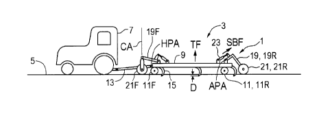
Fig. 1 is a schematic side view of an embodiment of system of the present
disclosure
for reducing implement wheel forces on an agricultural field surface;
Fig. 2 is a schematic top view of the system of Fig. 1;
1443367v1
6
CA 02871836 2014-11-21
=
Fig. 3 is a schematic side view showing a portion of the agricultural
implement frame
of Fig. 1 supported on a frame wheel and a support wheel, and showing the
forces
exerted;
Fig. 4 is a schematic side sectional view of the support hydraulic cylinder of
the system
of Fig. 1;
Fig. 5 is a schematic top view of the system of Fig. 1 with first and second
ground
engaging tools mounted on the implement frame, and a agricultural product cart
towed
behind the implement frame;
Fig. 6 is a schematic side view of the support arm and support wheel provided
by the
tongue and wheels of the cart of Fig. 5;
Fig. 7 is a schematic side view of a ground engaging tool provided by a
trailing arm
furrow opener assembly of the prior art;
Fig. 8 is a schematic side view of ground engaging tool provided by a disc
fertilizer
banding assembly of the prior art;
Fig. 9 is a schematic side view of the system of Fig. 1 where one support
hydraulic
cylinder is larger than the other..
DETAILED DESCRIPTION OF THE ILLUSTRATED EMBODIMENTS
Figs. 1 and 2 schematically illustrate an embodiment of a system 1 of the
present
disclosure for reducing implement wheel forces on an agricultural field
surface. An
agricultural implement 3 is connected to a tractor 7 for towing along the
field surface 5
and the implement 3 comprises an implement frame 9 mounted on a plurality of
frame
1443367v1
7
CA 02871836 2014-11-21
wheels 11 for travel in an operating travel direction T along the field
surface 5. The
illustrated implement 3 is of the floating hitch type with front and rear
frame wheels 11
and a hitch 13 pivotally attached to the implement frame 9 about a hitch pivot
axis HPA.
As is known in the art the front frame wheels 11F are caster wheels.
A plurality of ground engaging tools 15 are mounted on the implement frame 9,
and the
frame wheels 11 support the implement frame 9 and ground engaging tools 15 in
a
desired orientation with respect to the field surface 5, with the implement
frame 9
substantially parallel to the field surface 5. A tool control is operative to
move the
ground engaging tools 15 down to penetrate the field surface 5 to a desired
working depth
D. In the illustrated implement 3 the tool control is provided by an actuator,
such as a
tool hydraulic cylinder 17 as described below, on each ground engaging tool 15
which
moves the corresponding tool 15 up and down. The working depth is selected by
adjusting a gauge wheel, packer wheel, or the like mounted on the tool 15.
When
penetrating the field surface 5, the ground engaging tools 15 exert an upward
tool force
TF on the implement frame 9.
A plurality of support arms 19 are movably connected to the implement frame 9
and a
support wheel 21 is rotatably mounted to a wheel end of each support arm 19.
In the
illustrated system 1 the end of each support arm 19 opposite the wheel end
thereof is
pivotally connected to the implement frame 9 about a substantially horizontal
arm pivot
axis APA. The front support arms 19F extend forward from a front end of the
implement
frame 9 and a front support wheel 21F is pivotally mounted on the wheel end of
each
front support arm 19F about a vertical caster axis CA. The rear support arms
19R extend
rearward from a rear end of the implement frame 9 and a rear support wheel 21F
is
mounted on the wheel end of each rear support arm 19R. It is contemplated that
support
arms could extend laterally from right and left sides of the implement frame 9
as well
however same would need to be raised to a position above the implement frame 9
when
working adjacent to obstacles.
1443367v1 8
CA 02871836 2014-11-21
A support bias element, illustrated as a support hydraulic cylinder 23, is
operative to exert
a support bias force SBF on each support arm 19 to push the corresponding
support
wheel 21 against the field surface 5 and to correspondingly urge the implement
frame 9
upward with respect to the support wheel 21 to transfer a supported frame
weight SFW
from the implement frame 9 to the support wheels 21, such that an unsupported
frame
weight UFW is carried on the frame wheels 11. Fig. 3 schematically illustrates
the forces
that are in place at one location on the agricultural implement 3.
Thus the system 1 of the present disclosure transfers a portion of the weight
of the
implement frame 9 from the frame wheels 11 to the support wheels 21 and
reduces the
implement wheel forces exerted on the field surface 5 by the frame wheels 11.
The
support bias forces SBF are selected to maintain the unsupported frame weight
UFW at a
level greater than the upward tool force TF. If the support bias forces SBF
were at a level
such that the unsupported frame weight UFW was less than the upward tool force
TF the
frame wheels 11 would be lifted off the field surface 5 and the desired
orientation of the
implement frame 9 and ground engaging tools 15 with respect to the field
surface 5 could
not be maintained.
For any given implement 3, the upward tool force TF varies depending on the
working
depth D, soil conditions, and like factors. For example in some types of
agricultural
implements when the working depth D increases, the upward tool force TF
increases,
such that the support bias forces SBF must be decreased to avoid lifting the
frame wheels
11 above the field surface 5. Similarly in order to maintain a desired level
of support
when the desired working depth D decreases such that the upward tool force TF
decreases, the support bias forces SBF must be increased.
Ideally it is desirable to select the support bias forces so that the downward
force on each
square inch of field surface was the same under each of the wheels 11, 21. The
frame
1443367v1 9
CA 02871836 2014-11-21
wheels 11 and support wheels 21 exert a downward wheel pressure on the field
surface
depending on a size of a corresponding frame wheel tire and support wheel
tire, and
ideally the support bias forces are selected such that the downward wheel
pressure
exerted by the frame wheels 11 is about equal to the downward wheel pressure
exerted by
the support wheels 21.
Where the frame wheels 11 and support wheels 21 are about the same size the
support
bias forces SBF would be selected such that the portion of supported frame
weight SFW
carried by each support wheel 21 is about equal to the portion of unsupported
frame
weight UFW carried by each frame wheel 11. Typically however, as seen in the
illustrated system 1, the support wheels 21 are larger than the frame wheels
11 and so
have a larger weight bearing footprint and the support bias forces SBF are
selected such
that the portion of supported frame weight SFW carried by each support wheel
21 is
greater than the portion of unsupported frame weight UFW carried by each frame
wheel
11.
The upward tool force that results from the engagement of the tools 15 in the
ground is
not the same at each location on the implement frame 9 and, similarly the so
the
unsupported frame weight UFW carried by each frame wheel 11 is not the same.
For
example in shank type tools that drag through the ground, draft forces
required to pull the
tool through the ground increase as working depth increases. In a floating
hitch type
implement such as schematically illustrated in Figs. 1 and 2 with front and
rear frame
wheels 11F, 11R, the rear drag forces on the ground engaging tools 15 below
the hitch
pivot axis HPA create a moment about the hitch pivot axis HPA that can
transfer weight
from the rear end of the implement frame 9 to the front end of the implement
frame 9,
thereby reducing the frame weight carried by each rear frame wheel 11R and
increasing
the frame weight carried by each front frame wheel 11F.
1443367v1 10
CA 02871836 2014-11-21
=
In contrast disc type ground engaging tools 15 require considerable downward
force to
push them into the ground but roll through the ground and so create less drag
forces.
Thus in the implement described in Fig. 5 with disc type ground engaging tools
15 along
the front of the implement frame increasing the working depth of the discs
will urge the
front of the frame 9 and the front frame wheels 11RF upward and transfer
weight to the
rear frame wheels 11R.
Similarly when the implement is an air seeder, hard soils also typically
require increased
packing forces so that where the ground engaging tools 15 are trailing arm
furrow opener
assemblies as described below, the downward force on the packer wheels is
increased,
thus increasing the upward tool force all along the implement frame 9.
Thus it can be seen that determining the degree, direction, and location of
the forces
acting on the implement frame 9 and the frame wheels 11 is quite complex. In
practice
the support bias forces SBF at different locations on the implement frame 9
will be
selected based on experience of the effects on upward tool force TF of the
various
conditions such as working depth D, soil hardness, etc. on the particular
implement in
question. To ensure the upward tool force TF does not exceed the unsupported
frame
weight UFW, a force sensor 25, as schematically illustrated in Fig. 3, could
be located to
determine a portion of the unsupported frame weight UFW being carried by one
of the
frame wheels 11, and connected to a force indicator 27 to indicate same to an
operator in
the tractor. The operator can then reduce the support bias forces to a minimum
or zero
and the indicator 27 will show about the total frame weight carried on the
frame wheel
11, and then increase the support bias force to achieve a suitable unsupported
frame
weight, based on tire size, location of the sensor, and like factors. Force
sensors 25 could
be located on a number of different frame wheels 11, since the frame weight
carried by
frame wheels at different locations will typically be different.
1443367v1
11
CA 02871836 2014-11-21
=
The support bias elements are provided by support hydraulic cylinders 23, and
each
support hydraulic cylinder 23 is mounted at one end to the implement frame 9
and
mounted at an opposite end thereof to the corresponding support arm 19. An
active
support hydraulic source 29, provided typically by the tractor 7, is operative
to direct
pressurized hydraulic fluid, as schematically illustrated in Fig. 4, into a
first port 23A of
each support hydraulic cylinder 23 and allow the hydraulic fluid to flow into
and out of
the first port 23A to allow the support hydraulic cylinder 23 to extend and
retract while
exerting the support bias force SBF. A support bias control 31 is operative to
vary a
pressure of the hydraulic fluid to vary the support bias force SBF.
The illustrated active support hydraulic source 29 directs pressurized
hydraulic fluid into
the first port 23A of each support hydraulic cylinder 23 at substantially the
same
pressure. In some applications it may be desirable to have larger or smaller
support bias
forces at different locations on the implement frame 9 to ensure that each
frame wheel 11
maintains contact with the ground at those locations where the frame wheel 11
supports a
lesser frame weight, while also providing the desired frame support.
The support bias force SBF on any one of the support arms 19 can be varied by
varying
the pressure at the corresponding support hydraulic cylinder 23. For example
Fig. 1
schematically illustrate the support hydraulic cylinders 23F that are
connected to the
support arms 19F along the front of the implement frame 9 are connected to
receive
hydraulic fluid from the support hydraulic source 29 through a first pressure
control 29A,
and the support hydraulic cylinders 23R that are connected to the support arms
19R along
the rear of the implement frame 9 are connected to receive hydraulic fluid
from the
support hydraulic source 29 through a second pressure control 29B.
Varying the support bias force SBF on any one of the support arms 19 can also
be
accomplished by providing support hydraulic cylinders 23 that have different
diameters
1443367v1 12
CA 02871836 2014-11-21
and so will provide different support bias forces when the same pressure is
supplied to
each one.
Fig. 9 schematically illustrates an implement frame 9 with first and second
support
hydraulic cylinders 23S, 23L connected to the active hydraulic source 29. The
first
support hydraulic cylinder 23S has a first diameter D1 and exerts a first
support bias
force SBF1 on a first support arm 19S, and a second support hydraulic cylinder
23L has a
second diameter D2 greater than the first diameter D1 and therefore exerts a
second
support bias force SBF2 on a second support arm 19L that is greater than the
first support
bias force SBF1.
Each support arm 19 can also be moved to a transport position, schematically
indicated
by phantom lines in Fig. 3, by directing pressurized hydraulic fluid into the
second port
23B of the support hydraulic cylinder 23 to raise the support arm 19 and
mounted support
wheel 21 above the field surface. Depending on the configuration of the
agricultural
implement 3 when in a transport position, a suitable position for the support
arm 19 and
wheel 21 can be selected.
Figs. 5 and 6 schematically illustrate the agricultural implement 3 comprising
a cart 33
connected to a rear end of the implement frame by one of the support arms 19'
such that
the cart 33 is pulled in the operating travel direction T behind the implement
frame 9, and
wherein the corresponding support wheel 21' is provided by front wheels of the
cart 33.
The cart 33 is a product cart that carries agricultural products such as seed
and fertilizer
and is connected to the implement frame 9 by a tongue 19' which can be used as
a
support arm. The tongue 19' is connected to the front wheels 21' of the cart
33 by a
steering mechanism 35 configured such that moving the tongue 19' laterally
pivots the
front wheels 21' about substantially vertical wheel axes WA to steer the front
wheels 21'
to follow the implement frame 9 through turns. The tongue 19' has a first end
19A'
1443367v1 13
CA 02871836 2014-11-21
pivotally connected to a rear side of the implement frame 9 about a
substantially vertical
first tongue axis TAl. The second end 19B' of the tongue 19' is pivotally
connected to
the steering mechanism 35 about a substantially horizontal second tongue axis
TA2
oriented substantially horizontally and perpendicular to the operating travel
direction T.
The rear end of the support hydraulic cylinder 23' is mounted to the steering
mechanism
35, and the front end of the support hydraulic cylinder 23' is connected to
the hitch
tongue 19' forward of the second tongue axis TA2.
Directing pressurized hydraulic fluid into the first end 23A' of the support
hydraulic
cylinder 23' and extends same and pivots the hitch tongue 19' upward about the
second
tongue axis TA2 and the first end 19A' of the hitch tongue 19' forces the
implement
frame 9 upward to transfer weight from the implement frame 9, and the frame
wheels 11,
to the front cart wheels 21' in the same manner as the other support arms and
wheels 19,
21 described above.
In a common agricultural implement 3 for seeding crops, the ground engaging
tools 15
comprise trailing arm furrow opener assemblies as are known in the prior art
and as
schematically illustrated in Fig. 7. Each trailing arm furrow opener assembly
15
comprises an opener arm 39 pivotally attached at a front end thereof to the
implement
frame 9, and a packer wheel 41 rotatably mounted to a rear end of the opener
arm 39. A
furrow opener 43 extends down from the opener arm 39 and a tool hydraulic
cylinder 17
is operative to exert a downward tool bias force TBF on the opener arm 39 to
push the
furrow opener 43 down into engagement with the field surface 5.
The tool hydraulic cylinders 17 are connected to an active tool hydraulic
source 45 with a
pressure that is independent of the pressure of the active support hydraulic
source 29, and
a tool bias control 47 operative to vary the tool bias force TBF. The tool
bias force TBF
is increased or decreased depending on soil conditions, working depth, desired
packing
force, and like considerations. It can be seen that when the tool bias force
TBF increases
1443367v1 14
CA 02871836 2014-11-21
=
the upward tool force TF increases and weight is transferred from the
implement frame 9
to the packer wheels 41, reducing the frame weight carried on the frame wheels
11 and
support wheels 21. To maintain the proper load bearing relationship between
the frame
wheels 11 and support wheels 21, the support bias forces SBF are decreased
when the
tool bias forces TBF are increased, and similarly the support bias forces are
increased
when the tool bias forces are decreased.
In some cases first and second types of ground engaging tools that perform
different
operations may be mounted on the implement frame 9. Fig. 5 schematically
illustrates
first ground engaging tools being trailing arm furrow opener assemblies 15 as
described
above, mounted on middle and rear lateral bars of the implement frame 9, and
second
ground engaging tools being disc fertilizer banding assemblies 15' as
schematically
illustrated in Fig. 8 comprising a disc 49 mounted on the front lateral member
of the
implement frame 9 by a bracket 51 such that the disc 49 may be moved up and
down and
into or out of engagement with the field surface 5. When only the first ground
engaging
tools 15 are penetrating the field surface 5 a first support bias force SBF
will be suitable,
and when the second ground engaging tools 15' are lowered to penetrate the
field surface
5 the upward tool force TF will change and the support bias force will need to
be adjusted
correspondingly to a different suitable support bias force.
The present disclosure provides a method of reducing implement wheel forces on
an
agricultural field surface 5. The method comprises providing an agricultural
implement 3
comprising an implement frame 9 mounted on a plurality of frame wheels 11 for
travel in
an operating travel direction T and a plurality of ground engaging tools 15
mounted on
the implement frame 9, and wherein the frame wheels 11 support the implement
frame 9
and ground engaging tools 15 in a desired orientation with respect to the
field surface 5;
movably connecting a plurality of support arms 19 to the implement frame 9 and
rotatably mounting a support wheel 21 to a wheel end of each support arm 19;
towing
the agricultural implement 3 along the field surface with the ground engaging
tools 15
1443367v1 15
CA 02871836 2014-11-21
penetrating the field surface 5 to a desired working depth D, wherein the
ground
engaging tools 15 exert an upward tool force TF on the implement frame 9 that
is less
than a downward force exerted by a frame weight of the implement frame 9;
exerting a
support bias force SBF on each support arm 19 to push the support wheel 21
against the
field surface 5 and to correspondingly urge the implement frame 9 upward with
respect to
the support wheels 21 to transfer a supported frame weight SFW from the
implement
frame 9 to the support wheels 21, such that an unsupported frame weight UFW is
carried
on the frame wheels 11; and selecting the support bias forces SBF such that
the
unsupported frame weight UFW is greater than the upward tool force TF.
The present disclosure provides a system and method for reducing wheel forces
exerted
on agricultural field surfaces, thereby reducing compaction and loss of soil
productivity.
In the present disclosure the weight of the implement frame is spread over
more wheels,
thus reducing the weight on each wheel. In addition to reducing compaction, in
very soft
field surfaces the tendency of the frame wheels to sink into soft ground is
reduced.
The support system may be mounted on all sides of the implement to support all
sides, or
may be mounted only on locations where more support is desirable. The arms and
wheels of the system can be located at convenient locations where interference
with
functionality of the implement is minimized. Since the support wheels 21 do
not dictate
the orientation of the implement frame 9 and ground engaging tools 15, many of
the
problems associated with positioning larger wheels for increased support on an
implement frame are avoided.
The foregoing is considered as illustrative only of the principles of the
invention.
Further, since numerous changes and modifications will readily occur to those
skilled in
the art, it is not desired to limit the invention to the exact construction
and operation
shown and described, and accordingly, all such suitable changes or
modifications in
1443367v1
16
CA 02871836 2014-11-21
structure or operation which may be resorted to are intended to fall within
the scope of
the claimed invention.
1443367v1
17