Note: Descriptions are shown in the official language in which they were submitted.
CA 02871925 2014-11-20
DIFFERENTIAL PRESSURE INDICATOR FOR DOWNHOLE ISOLATION VALVE
BACKGROUND OF THE DISCLOSURE
Field of the Disclosure
The present disclosure generally relates to a differential pressure indicator
for
a downhole isolation valve.
Description of the Related Art
A wellbore is formed to access hydrocarbon bearing formations, e.g. crude oil
and/or natural gas, by the use of drilling. Drilling is accomplished by
utilizing a drill bit
that is mounted on the end of a drill string. To drill the wellbore, the drill
string is
rotated by a top drive or rotary table on a surface platform or rig, and/or by
a
downhole motor mounted towards the lower end of the drill string. After
drilling a first
segment of the wellbore, the drill string and drill bit are removed and a
section of
casing is lowered into the wellbore. An annulus is thus formed between the
string of
casing and the formation. The casing string is cemented into the wellbore by
circulating cement into the annulus defined between the outer wall of the
casing and
the borehole. The combination of cement and casing strengthens the wellbore
and
facilitates the isolation of certain areas of the formation behind the casing
for the
production of hydrocarbons.
An isolation valve assembled as part of the casing string may be used to
temporarily isolate a formation pressure below the isolation valve such that a
drill
string, work string, completions string, or wireline may be quickly and safely
inserted
into or removed from a portion of the wellbore above the isolation valve that
is
temporarily relieved to atmospheric pressure. Since the pressure above the
isolation
valve is relieved, the drill/work string can be tripped into the wellbore
without wellbore
pressure acting to push the string out and tripped out of the wellbore without
concern
for swabbing the exposed formation.
1
CA 02871925 2014-11-20
Before reopening the valve, pressure above the valve is equalized with
pressure below the valve in order to avoid damage thereto. The differential
pressure
across the valve is determined using available known parameters. However, this
results in only an estimate of the differential pressure.
SUMMARY OF THE DISCLOSURE
The present disclosure generally relates to a differential pressure indicator
for
a downhole isolation valve. In one embodiment, a differential pressure
indicator (DPI)
for use with a downhole isolation valve includes a tubular mandrel for
assembly as
part of a casing string and for receiving a tubular string. The mandrel has a
stop
shoulder and a piston shoulder. The DPI further includes a tubular housing for
assembly as part of the casing string and for receiving the tubular string.
The housing
is movable relative to the mandrel between an extended position and a
retracted
position and has a stop shoulder and a piston shoulder. The DPI further
includes a
hydraulic chamber formed between the piston shoulders and a coupling in
communication with the hydraulic chamber and for connection to a sensing line.
The
housing is movable relative to the mandrel and to the extended position in
response
to tension exerted on the DPI.
In another embodiment, a method of constructing a wellbore includes
deploying a tubular string into the wellbore through a casing string disposed
in the
wellbore. The casing string has an isolation valve in a closed position and a
hydraulic
sensing line extending along the casing string. The method further includes:
equalizing pressure across the isolation valve using the sensing line to
determine
differential pressure across the isolation valve; opening the isolation valve;
and
lowering the tubular string through the open valve.
In another embodiment, an isolation valve for use in drilling a wellbore
includes: a tubular housing for assembly as part of a casing string and for
receiving a
drill string; a seat disposed in the housing and longitudinally movable
relative to the
housing; a flapper pivotally connected to the seat between an open position
and a
2
CA 02871925 2014-11-20
closed position; a flow tube longitudinally movable relative to the housing
for opening
the flapper; a hydraulic chamber formed between the flow tube and the housing
and
receiving a piston of the flow tube; a hydraulic passage in fluid
communication with
the chamber and a hydraulic coupling; and a differential pressure indicator
(DPI)
linked to the seat for responding to force exerted on the seat by the flapper
in the
closed position.
In another embodiment, an isolation valve for use in drilling a wellbore
includes a tubular housing: for assembly as part of a casing string, for
receiving a drill
string, and having a shoulder formed in an inner surface thereof for receiving
the
seat. The isolation valve further includes: a seat disposed in the housing and
longitudinally movable relative to the housing; a flapper pivotally connected
to the
seat between an open position and a closed position; a flow tube
longitudinally
movable relative to the housing for opening the flapper; a hydraulic chamber
formed
between the flow tube and the housing and receiving a piston of the flow tube;
a
hydraulic passage in fluid communication with the chamber and a hydraulic
coupling;
and a differential pressure indicator (DPI) for measuring force exerted on the
isolation
valve when the flapper is in the closed position.
BRIEF DESCRIPTION OF THE DRAWINGS
So that the manner in which the above recited features of the present
disclosure can be understood in detail, a more particular description of the
disclosure,
briefly summarized above, may be had by reference to embodiments, some of
which
are illustrated in the appended drawings. It is to be noted, however, that the
appended drawings illustrate only typical embodiments of this disclosure and
are
therefore not to be considered limiting of its scope, for the disclosure may
admit to
other equally effective embodiments.
Figures 1A-1C illustrate a terrestrial drilling system in a drilling mode,
according to one embodiment of the present disclosure.
3
CA 02871925 2014-11-20
Figures 2A and 2B illustrate a differential pressure indicator (DPI) of the
drilling
system.
Figures 3A-3C illustrate operation of the DPI.
Figures 4A-4D illustrate isolation valves having integrated DPIs, according to
other embodiments of the present disclosure.
Figures 5A-5C illustrate further isolation valves having integrated DPIs,
according to other embodiments of the present disclosure.
DETAILED DESCRIPTION
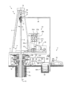
Figures 1A-1C illustrate a terrestrial drilling system 1 in a drilling mode,
according to one embodiment of the present disclosure. The drilling system 1
may
include a drilling rig 1r, a fluid handling system if, a pressure control
assembly (PCA)
1 p, and a drill string 5. The drilling rig 1r may include a derrick 2 having
a rig floor 3
at its lower end. The rig floor 3 may have an opening through which the drill
string 5
extends downwardly into the PCA 1p. The drill string 5 may include a
bottomhole
assembly (BHA) 33 and a conveyor string. The conveyor string may include
joints of
drill pipe 5p connected together, such as by threaded couplings. The BHA 33
may
be connected to the conveyor string, such as by threaded couplings, and
include a
drill bit 33b and one or more drill collars 33c connected thereto, such as by
threaded
couplings. The drill bit 33b may be rotated 4r by a top drive 13 via the
conveyor
string and/or the BHA 33 may further include a drilling motor (not shown) for
rotating
the drill bit. The BHA 33 may further include an instrumentation sub (not
shown),
such as a measurement while drilling (MWD) and/or a logging while drilling
(LWD)
sub.
An upper end of the drill string 5 may be connected to a quill of the top
drive
13. The top drive 13 may include a motor for rotating 4r the drill string 5.
The top
drive motor may be electric or hydraulic. A frame of the top drive 13 may be
coupled
to a rail (not shown) of the derrick 2 for preventing rotation thereof during
rotation of
4
CA 02871925 2014-11-20
the drill string 5 and allowing for vertical movement of the top drive with a
traveling
block 14. The frame of the top drive 13 may be suspended from the derrick 2 by
the
traveling block 14. The traveling block 14 may be supported by wire rope 15
connected at its upper end to a crown block 16. The wire rope 15 may be woven
through sheaves of the blocks 14, 16 and extend to drawworks 17 for reeling
thereof,
thereby raising or lowering 4a the traveling block 14 relative to the derrick
2.
The PCA 1p may include, one or more blow out preventers (B0P5) 18u,b, a
flow cross 19, a variable choke valve 20, a control station 21, one or more
shutoff
valves 27c,r, one or more pressure gauges 28d,r, a hydraulic power unit (HPU)
35, a
hydraulic manifold 36, an auxiliary valve 31, one or more control lines 37o,c,
a
sensing line 37s, a choke spool 39, a differential pressure indicator (DPI)
40, and an
isolation valve 50. A housing of each BOP 18u,b and the flow cross 19 may each
be
interconnected and/or connected to a wellhead 6, such as by a flanged
connection.
The wellhead 6 may be mounted on an outer casing string 7 which has been
deployed into a wellbore 8 drilled from a surface 9 of the earth and cemented
10 into
the wellbore. An inner casing string 11 has been deployed into the wellbore 8,
hung
from the wellhead 6, and a portion 11c thereof cemented 12 into place. The
inner
casing string 11 may extend to a depth adjacent a bottom of an upper formation
22u.
The upper formation 22u may be non-productive and a lower formation 22b may be
a
hydrocarbon-bearing reservoir. The inner casing string 11 may include a casing
hanger 11h, a plurality of casing joints connected together, such as by
threaded
couplings, the DPI 40, the isolation valve 50, and a guide shoe 23. The inner
casing
string may have a free portion 11f including the hanger 11h, a plurality of
casing
= joints, the DPI 40, and the isolation valve 50, and the cemented portion
11c including
the guide shoe 23 and a plurality of casing joints. A casing annulus 34c may
be
formed between the inner casing string 11 and the outer casing string 7 and
between
the inner casing string 11 and a portion of the wellbore 8 traversing the
upper
formation 22u. A free portion of the casing annulus 34c (adjacent to the
respective
free portion 11f) may be open (free from cement 12).
5
CA 02871925 2014-11-20
=
. ,
The sensing line 37s may extend from the HPU 35, through the wellhead 6,
along an outer surface of the inner casing string 11, and to the DPI 40. The
control
lines 37o,c may extend from the manifold 36, through the wellhead 6, along an
outer
surface of the inner casing string 11, and to the isolation valve 50. The
control lines
37o,c and sensing line 37s may be fastened to the inner casing string 11 at
regular
intervals. The control lines 37o,c may be bundled together as part of an
umbilical.
Alternatively, the sensing line 37s may also be bundled with the control lines
37o,c as part of the umbilical. Alternatively, instead of the inner casing
string, the
well may include a liner string hung from a bottom of the outer casing string
and
cemented into the wellbore and a tie-back casing string hung from the wellhead
and
having a lower end stabbed into a polished bore receptacle of the liner string
and the
DPI 40 and isolation valve 50 may be assembled as part of the tie-back casing
string.
Alternatively, the lower formation 22b may be non-productive (e.g., a depleted
zone),
environmentally sensitive, such as an aquifer, or unstable. Alternatively, the
wellbore
may be subsea having a wellhead located adjacent to the waterline and the
drilling
rig may be a located on a platform adjacent the wellhead. Alternatively, a
Kelly and
rotary table (not shown) may be used instead of the top drive.
The isolation valve 50 may include a tubular housing 51, an opener, such as a
flow tube 52, a closure member, such as a flapper 53, a seat 54, and a
receiver 55.
To facilitate manufacturing and assembly, the housing 51 may include one or
more
sections (only one section shown) each connected together, such by threaded
couplings and/or fasteners. Interfaces between the housing sections may be
isolated, such as by seals. The housing sections may include an upper adapter
(not
shown) and a lower adapter (not shown), each having a threaded coupling for
connection to other members of the inner casing string 11. The isolation valve
50
may have a longitudinal bore therethrough for passage of the drill string 5.
Although
shown as part of the housing 51, the seat 54 may be a separate member
connected
to the housing, such as by threaded couplings and/or fasteners. The receiver
55 may
be connected to the housing 51, such as by threaded couplings and/or
fasteners.
6
CA 02871925 2014-11-20
The flow tube 52 may be disposed within the housing 51 and be longitudinally
movable relative thereto between a lower position (shown) and an upper
position (not
shown). The flow tube 52 may have one or more portions, such as an upper
sleeve,
a lower sleeve, and a piston connecting the upper and lower sleeves. The flow
tube
piston may carry a seal for sealing an interface formed between an outer
surface
thereof and an inner surface of the housing 51. Alternatively, the flow tube
portions
52 may be separate members interconnected, such as by threaded couplings
and/or
fasteners.
A hydraulic chamber 56 may be formed in an inner surface of the housing 51.
The housing 51 may have shoulders formed in an inner surface thereof adjacent
to
the chamber 56. The housing 51 may carry an upper seal located adjacent to an
upper shoulder and a lower seal and wiper located adjacent to the lower
shoulder for
sealing the chamber 56 from the bore of the isolation valve 50. The hydraulic
chamber 56 may be defined radially between the flow tube 52 and the housing 51
and longitudinally between the upper and lower shoulders. Hydraulic fluid 61
may be
disposed in the chamber 56. The hydraulic fluid 61 may be an incompressible
liquid,
such as a water based mixture with glycol or a refined or synthetic oil. An
upper end
of the hydraulic chamber 56 may be in fluid communication with an opener
hydraulic
coupling 57o via an opener hydraulic passage 580 formed in and along a wall of
the
housing 51. A lower end of the hydraulic chamber 56 may be in fluid
communication
with a closer hydraulic coupling 57c via a closer hydraulic passage 58c formed
in and
along a wall of the housing 51.
The isolation valve 50 may further include a hinge 59. The flapper 53 may be
pivotally connected to the seat 54 by the hinge 59. The flapper 53 may pivot
about
the hinge 59 between an open position (shown) and a closed position (not
shown).
The flapper 53 may be positioned below the seat 54 such that the flapper may
open
downwardly. The flapper 53 may have an undercut formed in at least a portion
of an
outer face thereof. The flapper undercut may facilitate engagement of an outer
surface of the flapper 53 with a kickoff spring (not shown) connected to the
housing
7
CA 02871925 2014-11-20
=
. ,
51, such as by a fastener. An inner periphery of the flapper 53 may engage a
respective seating profile formed in an adjacent end of the seat 54 in the
closed
position, thereby sealing an upper portion of the valve bore from a lower
portion of
the valve bore. The interface between the flapper 53 and the seat 54 may be a
metal
to metal seal.
The hinge 59 may include a leaf, a knuckle of the flapper 53, one or more
flapper springs, and a fastener, such as hinge pin, extending through holes of
the
flapper knuckle and a hole of each of one or more knuckles of the leaf. The
seat 54
may have a recess formed in an outer surface thereof at an end adjacent to the
flapper 53 for receiving the leaf. The leaf may be connected to the seat 54,
such as
by one or more fasteners.
The flapper 53 may be biased toward the closed position by the flapper
springs, such as one or more inner and outer tension springs. Each tension
spring
may include a respective main portion and an extension. The seat 54 may have
slots
formed therethrough for receiving the flapper springs. An upper end of the
main
portions may be connected to the seat 54 at an end of the slots. The seat 54
may
also have a guide path formed in an outer surface thereof for passage of the
flapper
springs to the flapper 53. Ends of the extensions may be connected to an inner
face
of the flapper 53. The kickoff spring may assist the tension springs in
closing the
flapper 53 due to the reduced lever arm of the spring tension when the flapper
is in
the open position.
Alternatively, the hinge may include a torsion spring instead of the tension
springs and the kickoff spring. Alternatively, the leaf of the hinge 59 may be
free to
slide relative to the respective seat by a limited amount and a polymer seal
ring may
be disposed in a groove formed in the seating profile of the seat 54 such that
the
interface between the flapper inner periphery and the seating profile is a
hybrid
polymer and metal to metal seal. Alternatively, the seal ring may be disposed
in the
flapper inner periphery.
8
CA 02871925 2014-11-20
The flapper 53 may be opened and closed by interaction with the flow tube 52.
Downward movement of the flow tube 52 may engage the lower sleeve 52b thereof
with the flapper 53, thereby pushing and pivoting the flapper to the open
position
against the tension springs due to engagement of a bottom of the lower sleeve
with
an inner surface of the flapper. Upward movement of the flow tube 52 may
disengage the lower sleeve thereof with the flapper 53, thereby allowing the
tension
springs to pull and pivot the flapper to the closed position due to
disengagement of
the lower sleeve bottom from the inner surface of the flapper.
When the flow tube 52 is in the lower position, a flapper chamber 60 may be
formed radially between the housing 51 and the flow tube and the (open)
flapper 53
may be stowed in the flapper chamber. The flapper chamber 60 may be formed
longitudinally between the seat 54 and the receiver 55. The flow tube bottom
may be
positioned adjacent to an upper end of the receiver 55, thereby closing the
flapper
chamber 60. The flapper chamber 60 may protect the flapper 53 from abrasion by
the drill string 5 and from being eroded and/or fouled by cuttings in drilling
returns
31f. The flapper 53 may have a curved shape to conform to the annular shape of
the
flapper chamber 60 and the seating profile of the flapper seat 54 may have a
curved
shape complementary to the flapper curvature.
The control station 21 may include a console 21c, a microcontroller (MCU)
21m, and a display, such as a gauge 21g, in communication with the
microcontroller
21m. The console 21c may be in communication with the manifold 36 via an
operation line and be in fluid communication with the control lines 37o,c via
respective pressure taps. The console 21c may have controls for operation of
the
manifold 36 by the technician and have gauges for displaying pressures in the
respective control lines 37o,c for monitoring by the technician. The control
station 21
may further include a pressure sensor (not shown) in fluid communication with
the
DPI sensing line 37s via a pressure tap and the MCU 21m may be in
communication
with the pressure sensor to receive a pressure signal therefrom. The auxiliary
valve
31 may be assembled as part of the sensing line 37s and may be a shutoff valve
for
9
CA 02871925 2014-11-20
selectively providing fluid communication between the sensing line and the HPU
accumulator.
Alternatively, the auxiliary valve 31 may be incorporated into the manifold 36
and an upper end of the sensing line 37s may connect to the manifold.
The fluid system if may include a mud pump 24, a drilling fluid reservoir,
such
as a pit 25 or tank, a solids separator, such as a shale shaker 26, a return
line 29, a
feed line, a supply line 30, a mud-gas separator (MGS) 38s, and a flare 38f
(Figure
3A). A first end of the return line 29 may be connected to a branch of the
flow cross
19 and a second end of the return line may be connected to an inlet of the
shaker 26.
The returns pressure gauge 28r and returns shutoff valve 27r may be assembled
as
part of the return line 29. A first end of the choke spool 39 may be connected
to the
return line 29 between the returns pressure gauge 28r and the returns shutoff
valve
27r and a second end of the choke spool may be connected to the shaker inlet.
The
choke shutoff valve 27c, choke valve 20, and MGS 38s may be assembled as part
of
the choke spool 39. The MGS 38s may include an inlet and a liquid outlet
assembled
as part of the choke spool 39 and a gas outlet connected to the flare 38f or a
gas
storage vessel (not shown).
A lower end of the supply line 30 may be connected to an outlet of the mud
pump 24 and an upper end of the supply line may be connected to an inlet of
the top
drive 13. The supply pressure gauge 28d may be assembled as part of the supply
line 30p,h. A lower end of the feed line may be connected to an outlet of the
pit 25
and an upper end of the feed line may be connected to an inlet of the mud pump
24.
The returns pressure gauge 28r may be operable to monitor wellhead pressure.
The
supply pressure gauge 28d may be operable to monitor standpipe pressure.
The drilling fluid 32d may include a base liquid. The base liquid may be
refined or synthetic oil, water, brine, or a water/oil emulsion. The drilling
fluid 32d
may further include solids dissolved or suspended in the base liquid, such as
organophilic clay, lignite, and/or asphalt, thereby forming a mud.
CA 02871925 2014-11-20
Once the inner casing string 11 has been deployed into the wellbore 8 and
cemented 12 into place, the drill string 5 may then be deployed into the
wellbore until
the drill bit 33b is adjacent to the guide shoe 23. The drilling fluid 32d may
then be
circulated into the wellbore to displace chaser fluid (not shown) from a
drilling
annulus 34d formed between the drill string 5 and the inner casing string 11
and
between the drill string 5 and a portion of the wellbore 8 being drilled
through the
lower formation 22b. Once the drilling fluid 32d has filled the annulus 34d,
circulation
may be halted such that only hydrostatic pressure of the drilling fluid 32 is
exerted on
an inner surface of the upper sleeve 52u and hydrostatic pressure of the
hydraulic
fluid 61 is exerted on an outer surface of the upper sleeve 52u. If the
isolation valve
50 is not already open, the technician may operate the control station 21 to
place the
opener control line 37o in fluid communication with a reservoir of the HPU 35
via the
manifold 36. The technician may then operate the control station 21 to shut-in
the
opener line 37o, thereby hydraulically locking the piston 52p in place. The
technician
may then operate the control station 21 to place the closer line 37c in
communication
with the accumulator of the HPU 35 via the manifold 36 and then to shut in the
closer
line with an initial pressure.
Alternatively, the closer line 37c may be shut-in with no pressure or left
open
in fluid communication with the HPU reservoir. Alternatively, the opener line
37o may
be shut in at surface before deployment of the inner casing string 11.
To extend the wellbore 8 from the casing shoe 23 into the lower formation 22b,
the mud pump 24 may pump the drilling fluid 32 from the pit 25, through a
standpipe
and Kelly hose of the supply line 30 to the top drive 13. The drilling fluid
32d may
flow from the supply line 30 and into the drill string 5 via the top drive 13.
The drilling
fluid 32d may be pumped down through the drill string 5 and exit the drill bit
33b,
where the fluid may circulate the cuttings away from the bit and return the
cuttings up
the drilling annulus 34d. The returns 32r (drilling fluid plus cuttings) may
flow up the
drilling annulus 34d to the wellhead 6 and exit the wellhead at the flow cross
19. The
returns 32r may continue through the return line 29 and into the shale shaker
26 and
11
CA 02871925 2014-11-20
be processed thereby to remove the cuttings, thereby completing a cycle. As
the
drilling fluid 32d and returns 32r circulate, the drill string 5 may be
rotated 4r by the
top drive 13 and lowered 4a by the traveling block 14, thereby extending the
wellbore
8 into the lower formation 22b.
Figures 2A and 2B illustrate the DPI 40. The DPI 40 may include a tubular
mandrel 41m and a tubular housing 41h. The mandrel 41m and the housing 41h
may be longitudinally movable relative to each other between an extended
position
(Figure 2A) and a retracted position (Figure 2B). The DPI 40 may have a
longitudinal
bore therethrough for passage of the drill string 5. The mandrel 41h may
include two
or more sections, such as an adapter 42 and a piston 43, each connected
together,
such by threaded couplings (shown) and/or fasteners (not shown). The housing
41h
may include two or more sections, such as a piston 44 and an adapter 45, each
connected together, such by threaded couplings (shown) and/or fasteners (not
shown).
The mandrel adapter 42 may also have a threaded coupling (not shown)
formed at an upper end thereof for connection to another member of the inner
casing
string 11. The housing adapter 45 may also have a threaded coupling formed at
a
lower end thereof for connection to an upper end of the isolation valve 50.
The
housing adapter 45 may also carry a seal 47e for sealing an interface between
the
DPI 40 and the isolation valve 50. The mandrel adapter 42 may carry a seal 47a
for
sealing an upper interface formed between mandrel 41m and the housing 41h and
the mandrel piston 43 may carry a seal 47d for sealing a lower interface
formed
between mandrel and the housing, thereby sealing a bore of the DPI 40 from the
casing annulus 34c. The mandrel 41m and housing 41h may be made from a metal
or alloy, such as steel, stainless steel, or a nickel based alloy, having
strength
sufficient to support the isolation valve 50, any casing joints of the free
portion 11f
below the isolation valve, and the cemented portion 11c.
The mandrel piston 43 may have an upper portion 43u, a mid portion 43m
having an enlarged outer diameter relative to the upper portion, and a lower
portion
12
CA 02871925 2014-11-20
43b having an enlarged outer diameter relative to the mid portion. The upper
portion
43u may have the threaded coupling formed in an outer surface thereof and
connecting the mandrel piston 43 to the mandrel adapter 42. A piston shoulder
43p
may be formed between the upper 43u and mid 43m portions in an outer surface
of
the mandrel piston 43. A torsional coupling, such as spline teeth 43s and
spline
grooves, may be formed between the mid and lower 43b portions in the outer
surface
of the mandrel piston 43. An outer diameter of the mandrel adapter 42 may be
greater than an outer diameter of the mandrel piston upper portion 43u such
that a
lower end of the mandrel adapter may serve as a stop shoulder 42h. The
threaded
coupling connecting the mandrel piston 43 to the mandrel adapter 42 may be
formed
in an inner surface of the mandrel adapter 42 adjacent to the lower end
thereof.
The housing piston 44 may receive a lower portion of the mandrel adapter 42
and the upper 43u and mid 43m portions of the mandrel piston 43. The housing
piston 44 may have an upper portion 44u, a mid portion 44m having a reduced
inner
diameter relative to the upper portion, and a lower portion 44b having an
enlarged
inner diameter relative to the mid portion. A stop shoulder 44h may be formed
between the upper 44u and mid 44m portions in an inner surface of the housing
piston 44. A piston shoulder 44p may be formed between the mid 44m and lower
44b portions in the inner surface of the housing piston 44. The mid 44m and
lower
44b portions may have the threaded coupling connecting the housing piston 44
to the
housing adapter 45 formed in an outer surface thereof. A torsional coupling,
such as
spline teeth 44s and spline grooves, may be formed in a lower end of the
housing
piston 44. The housing adapter 45 may receive part of the mid portion 44m and
the
lower portion 44b of the housing piston 44 and the lower portion 43b of the
mandrel
piston 43. The housing adapter 45 may have an upper portion 45u, a lower
portion
45b having a reduced inner diameter relative to the upper portion, and a
shoulder
45h joining the upper and lower portions. The upper portion 45u may have the
threaded coupling connecting the housing piston 44 to the housing adapter 45
formed in an inner surface thereof.
13
CA 02871925 2014-11-20
Alternatively, each torsional coupling may include a keyway formed in the
respective housing 41h and mandrel 41m and the torsional connection completed
by
a key inserted therein.
The piston shoulders 43p, 44p may be engaged when the DPI 40 is in the
extended position and the stop shoulders 42h, 44h may be engaged when the DPI
40 is in the retracted position. A hydraulic chamber 46c may be formed
longitudinally
between the piston shoulders 43p, 44p when the DPI 40 is in the retraced
position.
The hydraulic chamber 46c may be formed radially between an inner surface of
the
mandrel piston upper portion 43b and an outer surface of the housing piston
lower
portion 44b. The housing piston 44 may carry a seal 47b in an inner surface of
the
mid portion 44m located adjacent to the piston shoulder 44p and the mandrel
piston
43 may carry a seal 47c in an outer surface of the mid portion 43m located
adjacent
to the piston shoulder 43p for sealing the hydraulic chamber 46c from the DPI
bore.
The hydraulic fluid 61 may be disposed in the chamber 46c. The hydraulic
chamber
46c may be in fluid communication with a hydraulic coupling 46f via a
hydraulic
passage 46p formed in a wall of and along the housing piston 44.
The DPI 40 may be biased toward the extended position by tension 62 exerted
on the DPI mandrel 41m by the free portion 11f being hung from the wellhead 6
and
weight of the DPI housing 41h, the isolation valve 50, any casing joints of
the free
portion 11f below the isolation valve, and the cemented portion 11c. Injection
of the
hydraulic fluid 61 into the chamber 46c may overcome the bias and retract the
DPI 40
by exerting upward pressure on the housing piston shoulder 44p and downward
pressure on the mandrel piston shoulder 43p. A stroke length of the DPI 40 may
be
infinitesimal relative to a length of the DPI 40, such as less than one tenth,
one
twentieth, one fiftieth, or one hundredth. The infinitesimal stroke length may
avoid
the need for slip joints in the control lines 37o,c and the sensing line 37s.
Torsional
connection between the housing 41h and the mandrel 41m may be maintained in
and
between the retracted and the extended positions by the engaged spline
couplings
43s, 44s.
14
CA 02871925 2014-11-20
Figures 3A-3C illustrate operation of the DPI 40. Referring specifically to
Figure 3A, during deployment of the inner casing string 11, deployment of the
drill
string 5, and drilling of the lower formation 22b, the isolation valve 50 may
be open
and the DPI 40 idle in the extended position.
Referring specifically to Figure 3B, after drilling of the lower formation 22b
to
total depth, the drill string 5 may be raised to such that the drill bit 33b
is above the
flapper 53. The technician may then open the auxiliary valve 31 to supply
pressurized hydraulic fluid 61 from the HPU accumulator to the DPI chamber 46c
via
the sensing line 37s, the coupling 46f, and the passage 46p. The DPI 40 may
stroke
to the retracted position at a threshold pressure 63t generating a retraction
force (not
shown) sufficient to overcome the tension 62 in the inner casing string 11 and
to
stretch the inner casing string 11 by amount corresponding to the stroke
length of the
DPI 40 (may be negligible due to infinitesimal stroke length). The HPU
accumulator
may have a level indicator for monitoring a volume expended therefrom to
retract the
DPI 40. Once the threshold pressure 63t has been reached, the technician may
then
close the auxiliary valve 31, thereby shutting in the DPI chamber 46c, and
instruct the
MCU 21m to record the threshold pressure.
If the tie-back alternative, discussed above, is employed, the retraction
force
generated by the threshold pressure may only need to overcome the tension in
the
tieback casing string. Alternatively, pressure may be monitored within the
system
while tension is pulled on its parent casing to correlate observed pressure
fluctuations with the initial tension set on the casing string.
Referring specifically to Figure 3C, the technician may then close the
isolation
valve 50 by operating the control station 21 to supply pressurized hydraulic
fluid 61
from the HPU accumulator to the closer passage 58c and to relieve hydraulic
fluid
from the opener passage 580 to the HPU reservoir. The pressurized hydraulic
fluid
61 may flow from the manifold 36 through the wellhead 6 and into the wellbore
via
closer line 37c. The pressurized hydraulic fluid 61 may flow down the closer
line 37c
and into the closer passage 58c via the hydraulic coupling 57c. The hydraulic
fluid
CA 02871925 2014-11-20
61 may exit the passage 58c into the hydraulic chamber lower portion and exert
pressure on a lower face of the flow tube piston, thereby driving the piston
upwardly
relative to the housing 51.
Alternatively, the drill string 5 may need to be removed for other reasons
before reaching total depth, such as for replacement of the drill bit 33b.
As the piston 52p begins to travel, hydraulic fluid 61 displaced from the
hydraulic chamber upper portion may flow through the opener passage 58o and
into
the opener line 370 via the hydraulic coupling 57o. The displaced hydraulic
fluid 61
may flow up the opener line 37o, through the wellhead 6, and exit the opener
line into
the hydraulic manifold 36. As the piston 52p travels and the lower sleeve 52b
clears
the flapper 53, the tension springs may close the flapper. Movement of the
piston
52p may be halted by abutment of an upper face thereof with the upper housing
shoulder. Once the flapper 53 has closed, the technician may then operate the
control station 21 to shut-in the closer line 37c or both of the control lines
37o,c,
thereby hydraulically locking the piston 52p in place. Drilling fluid 32 may
be
circulated (or continue to be circulated) in an upper portion of the wellbore
8 (above
the lower flapper) to wash an upper portion of the isolation valve 50. The
drill string 5
may then be retrieved to the rig 1r.
Once circulation has been halted and/or the drill string 5 has been retrieved
to
the rig 1r, pressure 64u in the inner casing string 11 acting on an upper face
of the
flapper 53 may be reduced relative to pressure 64b in the inner casing string
acting
on a lower face of the flapper, thereby creating a net upward force 65 on the
flapper
which is transferred to the DPI housing 41h via the isolation valve housing
51. Since
the net upward force 65 generated by the pressure differential 63u,b across
the
flapper 53 also tends to retract the DPI 40, the pressure in the DPI chamber
46c is
reduced to an indication pressure 63i.
The indication pressure 63i may be detected by the MCU 21m and used
thereby to calculate a delta pressure between the indication and threshold 63t
16
CA 02871925 2014-11-20
pressures. The MCU 21m may be programmed with a correlation between the
calculated delta pressure and the pressure differential 64u,b across the
flapper 53.
The MCU 21m may then convert the delta pressure to a pressure differential
across
the flapper 53 using the correlation. The MCU 21m may then output the
converted
pressure differential to the gauge 21g for monitoring by the technician.
The correlation may be determined theoretically using parameters, such as
geometry of the flapper 53, isolation valve housing 51, DPI housing 41h, and
DPI
mandrel 41m, and material properties thereof, to construct a computer model,
such
as a finite element and/or finite difference model, of the DPI 40 and
isolation valve 50
and then a simulation may be performed using the model to derive a formula.
The
model may or may not be empirically adjusted.
The control station 21 may further include an alarm (not shown) operable by
the MCU 21m for alerting the technician, such as a visual and/or audible
alarm. The
technician may enter one or more alarm set points into the control station 21
and the
MCU 21m may alert the technician should the converted annulus pressure violate
one of the set points. A maximum set point may be a design pressure of the
flapper
53. Weight of the DPI housing 41h, the isolation valve 50, any casing joints
of the
free portion 11f below the isolation valve, and the cemented portion 11c may
be
sufficient such that the tension 62 is greater than or equal to the net upward
force 65
generated by a pressure differential 64u,b equal to the design pressure of the
flapper
65, thereby ensuring that a measurement range of the DPI 40 is broad enough to
include the flapper design pressure.
If total depth has not been reached, the drill bit 33b may be replaced and the
drill string 5 may be redeployed into the wellbore 8. The DPI 40 may also be
used to
monitor differential pressure while tripping into the hole to gauge surge and
swab
effects.
Pressure in the upper portion of the wellbore 8 may then be equalized with
pressure in the lower portion of the wellbore 8 using the converted pressure
17
CA 02871925 2014-11-20
differential displayed by the gauge 21g to ensure proper equalization. The
technician
may then operate the control station 21 to supply pressurized hydraulic fluid
to the
opener line 37o while relieving the closer line 37c, thereby opening the
flapper 53.
Once the flapper 53 has been opened, the technician may then operate the
control
station 21 to shut-in the opener line 37c or both of the control lines 37o,c,
thereby
hydraulically locking the flow tube piston in place. Drilling may then resume.
In this
manner, the lower formation 22b may remain live during tripping due to
isolation from
the upper portion of the wellbore 8 by the closed isolation valve 50, thereby
obviating
the need to kill the lower formation 22b.
Once drilling has reached total depth, the drill string 5 may be retrieved to
the
drilling rig 1r, as discussed above. A liner string (not shown) may then be
deployed
into the wellbore 8 using a work string (not shown). The liner string and
workstring
may be deployed into the live wellbore 8 using the isolation valve 50, as
discussed
above for the drill string 5. Once deployed, the liner string may be set in
the wellbore
8 using the work string. The work string may then be retrieved from the
wellbore 8
using the isolation valve 50 as discussed above for the drill string 5. The
PCA 1p
may then be removed from the wellhead 6. A production tubing string (not
shown)
may be deployed into the wellbore 8 and a production tree (not shown) may then
be
installed on the wellhead 6. Hydrocarbons (not shown) produced from the lower
formation 22b may enter a bore of the liner, travel through the liner bore,
and enter a
bore of the production tubing for transport to the surface 9.
Alternatively, each piston shoulder 43p, 44p may be transposed with the
respective stop shoulder 42h, 44h, the passage 46p formed in a wall of and
along the
mandrel 41m instead of the housing 41h, thereby causing the indication
pressure 631
to increase with increasing differential pressure 63u,b across the flapper 53.
In a
further variant of this alternative, the DPI may have a pressure sensor in
fluid
communication with the DPI chamber and the sensing line may be an electric or
optical cable for transmission of a signal from the sensor to the control
station.
18
CA 02871925 2014-11-20
. .
Figures 4A-4D illustrate isolation valves 70, 80, 90, 100 having integrated
DPIs, according to other embodiments of the present disclosure.
Referring
specifically to Figure 4A, the isolation valve 70 may include a tubular
housing 71, an
opener, such as the flow tube 52, a closure member, such as the flapper 53,
the
opener coupling 57o, the closer coupling 57c, the hinge 59, a seat 74, a seat
receiver
75, and a flow tube receiver (not shown).
To facilitate manufacturing and assembly, the housing 71 may include one or
more sections (only one section shown) each connected together, such by
threaded
couplings and/or fasteners. Interfaces between the housing sections may be
isolated, such as by seals. The housing sections may include an upper adapter
and
a lower adapter, each having a threaded coupling for connection to other
members of
the inner casing string 11. The isolation valve 70 may have a longitudinal
bore
therethrough for passage of the drill string 5. The housing 71 may have the
hydraulic
chamber 56 (not shown) and the passages 58o,c (not shown) for operation of the
flow tube 52. Each of the flow tube receiver and seat receiver 75 may be
connected
to the housing 71. The housing may also have a piston shoulder 71s formed in
an
inner surface thereof.
The flapper 53 may be pivotally connected to the seat 74 by the hinge 59. An
inner periphery of the flapper 53 may engage a respective seating profile
formed in
an adjacent end of the seat 74 in the closed position, thereby sealing an
upper
portion of the valve bore from a lower portion of the valve bore. The
interface
between the flapper 53 and the seat 74 may be a metal to metal seal.
The seat 74 may be longitudinally movable relative to the housing 71 between
an upper position (not shown) and a lower position (shown). The seat 74 may be
stopped in the lower position by the seat receiver 75. The seat 74 may have a
piston
shoulder 74s formed in an inner surface thereof. The isolation valve 70 may
further
include a DPI chamber 76 formed longitudinally formed between the housing
shoulder and the seat shoulder 74s. The housing 71 may carry a seal located
adjacent to the shoulder 71s and the seat 74 may carry a seal located adjacent
to the
19
CA 02871925 2014-11-20
shoulder 74s for sealing the DPI chamber 76 from the bore of the isolation
valve 70.
The DPI chamber 76 may be defined radially between the seat 74 and the housing
71. Hydraulic fluid 61 may be disposed in the DPI chamber 76. The DPI chamber
76
may be in fluid communication with the sensing coupling 46f via a hydraulic
passage
78 formed in and along a wall of the housing 71. The sensing line 37s (not
shown)
may connect the coupling 46f to the control station 21 and the HPU 35.
In operation, the seat 74 may be maintained in the lower position by a
threshold pressure in the DPI chamber 76 and the DPI chamber being shut in by
the
valve 31 whether the isolation valve 70 is closed or open. When the isolation
valve
70 is closed, the MCU 21m may monitor pressure in the sensing line 37s,
calculate a
delta pressure, and use a correlation to calculate differential pressure
across the
flapper 53. As compared to the DPI 40, a net upward force on the flapper 53
will
increase pressure in the DPI chamber 76 instead of reducing pressure and the
isolation valve 70 may be located in either the free portion 11f or the
cemented
portion 11c.
Alternatively, the DPI chamber 76 may be in fluid communication with either
the opener passage or the closer passage and the sensing coupling 46f and
sensing
line 37s may be omitted.
Referring specifically to Figure 4B, the isolation valve 80 may include a
tubular
housing 81, an opener, such as the flow tube 52, a closure member, such as the
flapper 53, the opener coupling 57o, the closer coupling 57c, the hinge 59, a
seat 74,
a seat receiver (not shown), and a flow tube receiver (not shown). The valve
80 may
be similar to the valve 70 except that a biasing member, such as compression
spring
82 may be disposed in the DPI chamber 76. An upper end of the compression
spring
82 may bear against the housing shoulder 71s and a lower end of the
compression
spring may bear against the seat shoulder 74s, thereby biasing the seat 74
toward
the lower position. A stiffness and stroke of the spring 82 may be selected
such that
the spring may bottom out at the flapper design pressure. Further, the control
station
21 may include an accumulator 83 for operation of the isolation valve 80
having a
CA 02871925 2014-11-20
level sensor 84 in communication with the MCU21m and the shutoff valve 31 and
connection to the HPU 25 by the sensing line may be omitted.
In operation, the DPI chamber 76 may be in communication with the
accumulator 83 whether the isolation valve 80 is open or closed. When the
isolation
valve 80 is closed, a net upward force on the flapper 53 may drive the seat 74
upward against the spring 82, thereby expelling hydraulic fluid 61 from the
DPI
chamber 76 into the accumulator 83. The MCU 21m may monitor a fluid level in
the
accumulator 83 using the level sensor 84 to determine a volume of the
hydraulic fluid
61 expelled from the DPI chamber 76 and calculate a change in length of the
spring
82 using an area of the DPI chamber 76. Once the MCU 21m has calculated the
spring length, the MCU 21m may then determine the differential pressure across
the
flapper 53 using a stiffness of the spring 82 and geometry of the flapper 53.
Referring specifically to Figure 40, the isolation valve 90 may include a
tubular
housing 91, an opener, such as the flow tube 52, a closure member, such as the
flapper 53, the opener coupling 57o, the closer coupling 57c, the hinge 59, a
seat 94,
a biasing member, such as the compression spring 82, a DPI chamber 96, a seat
receiver (not shown), and a flow tube receiver (not shown). The valve 90 may
be
similar to the valve 80 except that the hydraulic fluid 61 may be omitted from
the DPI
chamber 96 and a proximity sensor 92s and target 92t disposed at respective
ends of
the DPI chamber 96. The housing 91 may have a sealed conduit 98 for receiving
leads 97 extending from the proximity sensor 92s to an electrical coupling
(not
shown, replaces hydraulic coupling 46f). A sensing cable (not shown) may
extend
from the isolation valve 90 to the control station 21 instead of the sensing
line 37s.
The sensing cable may extend to the control station 21 independently of the
control
lines 37o,c or be bundled therewith in the umbilical.
The target 92t may be a ring made from a magnetic material or permanent
magnet and may be mounted to the seat shoulder 94s by being bonded or press
fit
into a groove formed in the shoulder face. The sensor 92s may be mounted to
the
housing 91 adjacent to the shoulder 91s. Each of the housing 91 and the seat
94
21
CA 02871925 2014-11-20
. ,
may be made from a diamagnetic or paramagnetic material. The proximity sensor
92s may or may not include a biasing magnet depending on whether the target
92t is
a permanent magnet. The proximity sensor 92s may include a semiconductor and
may be in electrical communication with the leads 97 for receiving a regulated
current. The proximity sensor 92s and/or target 92t may be oriented so that
the
magnetic field generated by the biasing magnet/permanent magnet target is
perpendicular to the current. The proximity sensor 92s may further include an
amplifier for amplifying the Hall voltage output by the semiconductor when the
target
92t is in proximity to the sensor.
Alternatively, the proximity sensor may include, but is not limited to
inductive,
capacitive, optical, or utilization of wireless identification tags.
Alternatively, the
sensor 92s and target 92t may each be connected to a respective end of the
spring
82.
In operation, when the isolation valve 90 is closed, a net upward force on the
flapper 53 may drive the seat 94 upward against the spring 82, thereby moving
the
target 92t toward the sensor 92s. The MCU 21m may monitor the sensor 92s and
determine a length of the spring 82. The MCU 21m may then determine the
differential pressure across the flapper 53 using a stiffness of the spring 82
and
geometry of the flapper 53.
Referring specifically to Figure 4D, the isolation valve 100 may include a
tubular housing 101, an opener, such as the flow tube 52, a closure member,
such as
the flapper 53, the opener coupling 57o, the closer coupling 57c, the hinge
59, the
seat 94, a biasing member, such as the compression spring 82, a DPI chamber
96, a
seat receiver (not shown), and a flow tube receiver (not shown). The valve 100
may
be similar to the valve 90 except for having a position sensor 102i,o instead
of the
proximity sensor 92s and target 92t.
The position sensor 1021,0 may be a linear variable differential transformer
(LVDT) having an outer tube 102o and an inner ferromagnetic core 102i. The
outer
22
CA 02871925 2014-11-20
tube 102o may be disposed in the sealed conduit 108 and mounted to the housing
101. The outer tube 102o may be in electrical communication with the
electrical
coupling via leads (not shown). The inner core 102i may extend from the outer
tube
1020, through the DPI chamber 96 and have a lower end connected to the seat
shoulder 94s. The outer tube 1021 may have a central primary coil (not shown)
and a
pair of secondary coils (not shown) straddling the primary coil. The primary
coil may
be driven by an AC signal and the secondary coils monitored for response
signals
which may vary in response to position of the core 102i relative to the outer
tube
1020.
In operation, when the isolation valve 100 is closed, a net upward force on
the
flapper 53 may drive the seat 94 upward against the spring 82, thereby
contracting
the position sensor 102i,o. The MCU 21m may monitor the sensor 102i,o and
determine a length of the spring 82. The MCU 21m may then determine the
differential pressure across the flapper 53 using a stiffness of the spring 82
and
geometry of the flapper 53.
Alternatively, each end of the position sensor 102i,o may be connected to a
respective end of the spring 82.
Figures 5A-5C illustrate further isolation valves 110, 120, 130 having
integrated DPIs, according to other embodiments of the present disclosure.
Referring specifically to Figure 5A, the isolation valve 110 may include a
tubular
housing 111, an opener, such as the flow tube 52, a closure member, such as
the
flapper 53, the opener coupling 57o, the closer coupling 57c, the hinge 59, a
seat
114, an electrical coupling 116, and a flow tube receiver (not shown).
To facilitate manufacturing and assembly, the housing 111 may include one or
more sections (only one section shown) each connected together, such by
threaded
couplings and/or fasteners. Interfaces between the housing sections may be
isolated, such as by seals. The housing sections may include an upper adapter
and
a lower adapter, each having a threaded coupling for connection to other
members of
23
CA 02871925 2014-11-20
. ,
. ,
the inner casing string 11. The isolation valve 110 may have a longitudinal
bore
therethrough for passage of the drill string 5. The housing 110 may have the
hydraulic chamber 56 (not shown) and the passages 58o,c (not shown) for
operation
of the flow tube 52. Each of the flow tube receiver and seat receiver 75 may
be
connected to the housing 111. The housing may also have a shoulder 111s formed
in an inner surface thereof.
The upper adapter section may have one or more strain gages 112a,b
mounted on an outer surface thereof. Leads 117 may extend from each strain
gage
112a,b to the electrical coupling 116. A sensing cable (not shown) may extend
from
the isolation valve 110 to the control station 21. The sensing cable may
extend to the
control station 21 independently of the control lines 37o,c or be bundled
therewith in
the umbilical. Each strain gage 112a,b may be foil, semiconductor,
piezoelectric, or
magnetostrictive. Each strain gage 112a,b may be oriented (i.e., parallel or
diagonal)
relative to a longitudinal axis of the housing 111 to measure longitudinal
strain of the
upper adapter section due to force exerted thereon by the closed flapper 53.
Additional strain gages may be disposed on the upper adapter section to
account for
temperature and/or increase sensitivity.
The flapper 53 may be pivotally connected to the seat 114 by the hinge 59.
An inner periphery of the flapper 53 may engage a respective seating profile
formed
in an adjacent end of the seat 114 in the closed position, thereby sealing an
upper
portion of the valve bore from a lower portion of the valve bore. The
interface
between the flapper 53 and the seat 114 may be a metal to metal seal. The seat
114
may be linked to the housing, such as by a fastener 115 and slot 114t joint to
allow
limited longitudinal movement of the seat 114 relative to the housing 111
between an
upper position (shown) and a lower position (not shown). The seat 114 may have
a
shoulder 114s formed in an inner surface thereof. The seat 114 may be stopped
in
the upper position by engagement of the shoulders 114s, 111s.
In operation, when the isolation valve 110 is closed, a net upward force on
the
flapper 53 may push the seat 94 upward toward the housing 111 until the
shoulders
24
CA 02871925 2014-11-20
, .
114s, 111s engage, thereby relieving tension on the upper adapter section. The
MCU 21m may monitor the strain gages 112a,b and determine the force exerted on
the housing 111 by the closed flapper 53. The MCU 21m may then determine the
differential pressure across the flapper 53 using geometry of the flapper 53.
Referring specifically to Figure 5B, the isolation valve 120 may include a
tubular housing 121, an opener, such as the flow tube 52, a closure member,
such as
the flapper 53, the opener coupling 57o, the closer coupling 57c, the hinge
59, a seat
124, the slip joint 114t, 115, the electrical coupling 116, and a flow tube
receiver (not
shown). The valve 120 may be similar to the valve 110 except for having a load
cell
122 instead of the strain gages 112a,b.
A sensing cable (not shown) may extend from the isolation valve 120 to the
control station 21. The load cell 122 may be disposed in a sealed conduit 128
adjacent to a shoulder 121s formed in an inner surface of the housing 121 and
mounted to the housing. Leads 127 may extend from the load cell 122 to the
electrical coupling 116. The
load cell 122 may be hydraulic, pneumatic, or
mechanical (strain gage). An upper end of the seat 124 may serve as a shoulder
124s for engaging the load cell 122.
In operation, when the isolation valve 120 is closed, a net upward force on
the
flapper 53 may push the seat 124 upward toward the housing 121 until the
shoulder
124s engages the load cell 122. The MCU 21m may monitor the load cell 122 and
determine the force exerted thereon by the closed flapper 53. The MCU 21m may
then determine the differential pressure across the flapper 53 using geometry
of the
flapper 53.
Referring specifically to Figure 5C, the isolation valve 130 may include a
tubular housing 131, an opener, such as the flow tube 52, a closure member,
such as
the flapper 53, the opener coupling 57o, the closer coupling 57c, the hinge
59, a seat
124, the slip joint 114t, 115, the electrical coupling 116, and a flow tube
receiver (not
shown). The valve 130 may be similar to the valve 110 except for having a
strain
CA 02871925 2014-11-20
gage 112c mounted to the outer face of the flapper 53. The strain gage 112c
may be
similar to the strain gages 112a,b. Leads 137 may extend from the strain gage
112c
to the electrical coupling 116 via a sealed conduit 138. A sensing cable (not
shown)
may extend from the isolation valve 130 to the control station 21.
In operation, when the isolation valve 130 is closed, a net upward force on
the
flapper 53 may push the flapper against the profile of the seat 124 and the
seat
upward toward the housing 131 until the seat engages the housing. The MCU 21m
may monitor the strain gage 112c and determine the differential pressure
across the
flapper 53.
Alternatively, the strain gage 112c may be mounted on the flapper hinge 59.
Alternatively, the drilling system 1 may be a closed loop drilling system
including a rotating control device, a supply flow meter, a returns flow
meter, an
automated choke, and/or a gas chromatograph. The closed loop drilling system
may
be operated to perform a mass balance during drilling and exert variable
backpressure on the returns.
While the foregoing is directed to embodiments of the present disclosure,
other and further embodiments of the disclosure may be devised without
departing
from the basic scope thereof, and the scope thereof is determined by the
claims that
follow.
26