Note: Descriptions are shown in the official language in which they were submitted.
CA 02872560 2014-11-28
LED LAMP WITH DUAL MODE OPERATION
Field of the Invention
[000011 The present invention relates to an LED lamp with dual mode operation
from a
fluorescent lamp fixture wired to supply either mains power or power from an
electronic
ballast associated with the fixture.
Background of the Invention
[00002] One conventional, elongated LED lamp can be retrofit into an existing
fluorescent
lamp fixture whose wiring is reconfigured so as to directly supply mains power
to the LED
lamp. With such an LED "retrofit" lamp, power is typically supplied to the
lamp from a pair
of power connector pins on one end of the lamp, with the pair of connector
pins at the
other end of the lamp not powering the lamp but providing mechanical support
for the
lamp. The foregoing arrangement for powering the lamp from the power connector
pins at
one end of the lamp has the benefit of limiting exposure to potentially life-
threatening
electrical shock from the mains current to a lamp installer during lamp
installation.
[00003] A second conventional, elongated LED lamp can be retrofit into an
existing
fluorescent lamp fixture so as to use a fluorescent lamp electronic ballast
contained in the
fixture without reconfiguring the fixture wiring. As is the case with
fluorescent lamps, the
LED retrofit lamp obtains power from power connector pins at opposite ends of
the lamp. A
representative LED retrofit lamp of this type is disclosed in Patent No. US
8,089,213 B2 to
Park. The Park LED lamp has a single mode of operation from an existing
fluorescent lamp
ballast associated with a fluorescent lamp fixture. Park teaches the use of
capacitors C11¨
C14 in his FIG. 1 to "control the capacitance of a series resonant circuit of
a fluorescent lamp
ballast" at Col. 4, II. 26-30. Inasmuch as Park teaches fluorescent lamp
ballasts having a high
frequency of 50 KHz (Col. 8, I. 58 & Col. 11, I. 4), capacitors C11¨C14, of
necessity, have a
high impedance at typical mains frequencies of 50 or 60 Hz. Accordingly,
capacitors C11¨
C14 provide the benefit of sufficiently attenuating any current at typical
mains frequencies
so as to prevent a potentially life-threatening electrical shock hazard if the
LED retrofit lamp
is accidentally placed into a fluorescent lamp ballast wired directly to power
mains.
1
CA 02872560 2014-11-28
[00004] Lamp designers have recognized that it would be desirable to have an
LED retrofit
lamp with dual mode operation from either an existing fluorescent lamp ballast
associated
with a fluorescent lamp fixture, or directly from power mains. U.S. Patent No.
US 8,575,856
B2 to Chung et al. provides an LED lamp with dual mode operation. However, a
single circuit
is used to power LEDs in the lamp whether the power is supplied by AC mains or
whether
the power is supplied by an existing fluorescent lamp electronic ballast. This
attempt suffers
in potential performance regarding energy efficiency and stability compared to
an LED lamp
that operates only from AC mains power, or an LED lamp that operates only from
power
supplied by a fluorescent lamp electronic ballast.
[00005] The Chung et al. LED lamp is also flawed in that it fails to mitigate
a potentially life-
threatening electrical shock hazard when a lamp is placed into a fixture that
is wired directly
to power mains. This is because, in the case of AC mains operation, power is
applied across
the LED lamp through the same circuit used when the fluorescent lamp
electronic ballast is
present. As a result, a potential shock hazard is created, which may be life-
threatening to a
lamp installer during lamp installation.
[00006] It would, therefore, be desirable to provide an LED retrofit lamp with
dual mode
operation from an existing fluorescent lamp electronic ballast associated with
a fluorescent
lamp fixture, as well as, alternatively, directly from power mains that is
efficient and stable.
It would also be desirable to provide such as lamp that can avoid a potential
life-threatening
electrical shock hazard when such a lamp is placed into a fixture wired to
supply power
directly from power mains.
Summary of the Invention
[00007] The present invention combines dual modes of operation of an LED
retrofit lamp.
In a first mode, the LED retrofit lamp receives power from power mains in a
fluorescent
lamp fixture; in an alternative, second mode, the LED retrofit lamp receives
power from a
fluorescent lamp electronic ballast in a fluorescent lamp fixture. In the
first mode, the LED
lamp can be wired to receive power from a pair of power connector pins at one
end of the
lamp. In the second mode, the LED lamp receives power from a fluorescent lamp
electronic
ballast associated with the lamp fixture. The foregoing dual mode operation is
accomplished
through the use of first and second circuits respectively dedicated to the
first and second
2
CA 02872560 2014-11-28
modes of operation. While the first and second circuits share one common power
connector
pin on the LED lamp and typically power the same LEDs, the first and second
circuits may be
electrically isolated from each other via novel conduction control
arrangements.
[00008] In one form, the present invention provides an LED lamp with dual mode
operation
from a fluorescent lamp fixture wired to supply either mains power or power
from an
electronic ballast supplying AC power at a ballast frequency. The LED lamp
comprises an
elongated housing having first and second ends. A first end of the elongated
housing is
provided with first and second power connector pins. A second end of the
elongated
housing is provided with a third power connector pin. A first circuit is
intended to provide
primary power to at least one LED that is for being powered in a first mode
and that
provides light along a length of the elongated housing. The first mode occurs
when the LED
lamp is inserted into a fluorescent lamp fixture having electrical receptacles
that receive the
first and second power connector pins and that are directly connected to power
mains
supplying power at a mains frequency much lower than the ballast frequency.
The first
circuit limits current to the at least one LED for being powered in a first
mode. A second
circuit is intended to provide primary power to at least one LED that is for
being powered in
a second mode and that provides light along a length of the elongated housing.
The second
mode occurs when the LED lamp is inserted into a fluorescent lamp fixture
having electrical
receptacles that receive the second and third power connector pins, at
opposite lamp ends,
and that are connected to the electronic ballast for receiving power
therefrom. The second
circuit includes a rectifier circuit that receives power from the second and
third power
connector pins. A first conduction control means is serially connected between
the second
power connector pin and the rectifier circuit for permitting the second
circuit to power the
at least one LED for being powered in the second mode when the second and
third power
connector pins, at opposite lamp ends, are connected to the electronic
ballast. A second
conduction control means is serially connected between the third power
connector pin and
the rectifier circuit for permitting the second circuit to power the at least
one LED for being
powered in the second mode when the second and third power connector pins, at
opposite
lamp ends, are connected to the electronic ballast.
3
CA 02872560 2014-11-28
[00009] In some embodiments, the at least one LED for being powered in a first
mode and
the at least one LED for being powered in a second mode have at least one LED
in common.
In other embodiments, the at least one LED for being powered in a first mode
and the at
least one LED for being powered in a second mode do not have any LEDS in
common.
[000010] The foregoing LED lamp can be retrofit into an existing fluorescent
lamp fixture
and has dual mode operation from an existing fluorescent lamp electronic
ballast associated
with the lamp fixture, as well as, alternatively, directly from power mains.
Beneficially, the
LED lamp can be configured to mitigate a potentially life-threatening
electrical shock hazard
when such a lamp is placed into a fixture wired to supply power directly from
power mains.
Some embodiments of the inventive lamp are configured to provide additional
protection
against shock exposure to a lamp installer.
[000011] Further, the foregoing LED lamp is more efficient to operate than
using, as various
prior art references teach, a master circuit that senses whether a lamp
fixture supplies
power from an electronic ballast or directly from power mains, and that
provides
appropriate power to LEDs. Rather than using such a master circuit, as the
foregoing
summary of the invention teaches, the present invention uses first and second
circuits to
receive mains power or power from an existing fluorescent lamp ballast,
respectively. This
approach eliminates the energy loss that results when using an active LED
driver to
reprocess power from an existing fluorescent lamp ballast. This approach also
typically
allows the second circuit to be formed inexpensively from a few passive
components, such
as a diode rectifier circuit and one or more capacitors.
Brief Description of the Drawings
[000012] Further features and advantages of the invention will become apparent
from
reading the following detailed description in conjunction with the following
drawings, in
which like reference numbers refer to like parts:
[000013] FIG. 1 is an electrical schematic diagram, partially in block form,
of a fluorescent
lamp fixture that is wired to provide mains power directly to power connector
pins of an
LED lamp in accordance with the invention.
4
CA 02872560 2014-11-28
[000014] FIG. 2 is similar to FIG. 1, but provides mains power to all four
power receptacles
of the fluorescent lamp fixture.
[000015] FIGS. 3 and 4 are electrical schematic diagrams, partially in block
form, of a
fluorescent lamp fixture including a fluorescent lamp electronic ballast and
an LED lamp in
accordance with the invention.
[000016] FIG. 5 is an electrical schematic diagram of circuitry within the LED
lamp shown in
FIGS. 1-3.
[000017] FIG. 6 is an electrical schematic diagram of an LED power supply
including a high
frequency isolating transformer between electrical inputs and electrical
outputs.
[000018] FIG. 7 is an electrical schematic diagram of an LED power supply that
does not
include means for isolating electrical outputs from electrical inputs.
[000019] FIG. 8,9 and 10 are electrical schematic diagrams of circuities
within the LED lamp
shown in FIGS. 1-3 that are alternative to that shown in FIG. 5.
[000020] FIG. 11 shows various electrical schematic diagrams of alternative
embodiments
of the conduction control means shown in FIGS. 5 and in FIGS. 8-10 in tabular
form and
provides other qualifications for those embodiments.
Detailed Description
[0000211 The examples and drawings provided in the detailed description are
merely
examples, and should not be used to limit the scope of the claims in any claim
construction
or interpretation.
Definitions
[000022] In this specification and appended claims, the following definitions
apply:
[000023] An "active component" connotes a controllable electrical component
that
supplies controllable energy in the form of voltage or current to a circuit
containing the
active component. Examples of active components are transistors.
[000024] An "active circuit" connotes a circuit using a control loop that
incorporates
feedback and an active element for the purpose of limiting current to a load.
CA 02872560 2014-11-28
[000025] A "passive component" connotes an electrical component that is
incapable of
supplying externally controllable energy in the form of voltage or current
into a circuit
containing the passive component. Examples of passive components are
rectification diodes,
LED diodes, resistors, capacitors, inductors, or magnetic ballasts operating
at 50 or 60 Hz.
[000026] A "passive circuit" connotes a circuit that does not include an
active component
as defined herein.
[000027] An "electronic ballast for a fluorescent lamp" or the like connotes
an instant start
ballast, a rapid start ballast, a programmed start ballast, and other ballasts
that use switch-
mode power supplies to realize current-limiting for fluorescent lamps. An
"electronic ballast
for a fluorescent lamp ballast" does not include a so-called magnetic ballast.
[000028] "Power mains" connote the conductors through which AC or DC
electrical power
is supplied to end users. AC power is typically supplied at a frequency
between about 50
and 60 Hz, and typically between about 100 and 347 volt rms. Specialized power
mains
provide power at 400 Hz. A frequency of zero for power mains corresponds
herein to DC
power.
[000029] Other definitions are provided in the following description for
"conduction
control means" and "permit," by way of example.
Fluorescent Lamp Fixtures
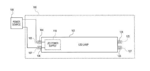
[000030] FIG. 1 shows an exemplary fluorescent lamp fixture 100 for an
elongated LED
lamp 102. Fluorescent lamp fixture 100 is wired to supply mains power from a
power source
108 to first and second power connector pins 104 and 106 via respective power
receptacles
105 and 107. Power receptacles 125 and 127, which are not wired to receive
mains power,
receive third and fourth power connector pins 124 and 126, respectively, so as
to
mechanically support the power connector pins. An LED power supply 110
conditions the
power supplied by power source 109 for driving LEDs (not shown) in LED lamp
102, such as
by limiting current to the LEDs.
[000031] Power source 109 may be an AC source with a typical power mains
frequency of
50 or 60 Hz or 400 Hz. Power source 109 may also be a DC power source, in
which case the
mains frequency is considered zero.
6
CA 02872560 2014-11-28
[000032] Referring again to FIG. 1, the claimed invention contemplates first
and second
power connector pins on one end of LED lamp 102 and a third power connector
pin 124 at
the other end of the lamp. It is not important that first power connector pin
106 be axially
displaced from third power connector pin 124 as shown in FIG. 1; they could
also be axially
aligned with each other.
[000033] FIG. 2 is similar to FIG. 1, but shows an exemplary fluorescent lamp
fixture 115
that provides mains power from power source 109 to all four power connector
pins 104,
106, 124 and 126 of LED lamp 102. Mains power is supplied to third and fourth
power
connector pins 124 and 126 via power receptacles 125 and 127, respectively, of
fluorescent
lamp fixture 115. LED power supply 110 conditions the power supplied by power
source 109
for driving LEDs (not shown) in LED lamp 102, such as by limiting current to
the LEDs. In
contrast to fluorescent lamp fixture 100 of FIG. 1, if LED lamp 102 is
inserted into
fluorescent lamp fixture 115 in the reverse direction, mains power would be
supplied to LED
power supply 110 via power receptacles 125 and 127.
[000034] FIG. 3 shows an exemplary fluorescent lamp fixture 120, including a
fluorescent
lamp electronic ballast 122, which supplies power to the same LED lamp 102 as
shown in
FIG. 1 or 2, but through different power connector pins from the fluorescent
lamp fixtures
100 and 115 of FIGS. 1 and 2. In FIG. 3, electrical power from fluorescent
lamp electronic
ballast 122 is supplied to LED lamp 102 through second power connector pin
106, via
electrical receptacle 107, and through third power connector pin 124, via
electrical
receptacle 127. Second and third power connector pins 106 and 126 are on
opposite ends
of the lamp. For convenience when using a fluorescent lamp electronic ballast
122 of the
instant start type, electrical receptacles 105 and 107 may optionally be
shorted together by
an electrical short 108, and electrical receptacles 125 and 127 may be shorted
together by
an electrical short 128. Fourth power connector pin 126 need not be connected
to circuitry
within the lamp, as indicated in the figure.
[000035] FIG. 4 shows an exemplary fluorescent lamp fixture 130, including a
fluorescent
lamp electronic ballast 122. As in FIG. 3, fluorescent lamp fixture 130
supplies power to the
same LED lamp 102 as shown in FIG. 1 or 2, but through different power
connector pins
from the fluorescent lamp fixtures 100 and 115 of FIGS. 1 and 2. The main
difference
7
CA 02872560 2014-11-28
between fluorescent lamp fixtures 120 (FIG. 3) and 130 (FIG. 4) is that
fluorescent lamp
fixture 130 provides separate conductors for each of power connector pins 104,
106, 124
and 126. The use of separate conductors is typical in regard to fluorescent
lamp fixtures 130
of the rapid start or programmed start, for instance.
[000036] It should be noted that the same LED lamp 102 is described with a
mode of
operating when directly wired to power mains in FIG. 1 or 2 and with a second
mode of
operating from a fluorescent lamp electronic ballast 122 as shown in FIG. 3 or
4.
Circuitry within LED Lamp
[000037] FIG. 5 shows circuitry 200 within LED lamp 102 of above-described
FIGS. 1-3.
Circuitry 200 includes a first circuit 210 and a second circuit 280, either of
which can power
LEDs 300 depending upon whether (a) fluorescent lamp fixture 100 or 115 (FIG.
1 or 2) or
(b) fluorescent lamp fixture 120 (FIG. 3) or 130 (FIG. 4) is to be used. LEDs
300 are shown
as a single string of series-connected LEDs. Serially connected string of LEDs
300 can be
replaced with routine skill in the art by one or more (a) parallel connected
strings of LEDs,
or (b) one or more parallel and serially connected strings of LEDs, or (c) a
combination of
the foregoing topologies (a) and (b). Capacitor 310 can be omitted if
alternative energy
storage for powering LEDs 300 is provided. By way of example, such alternate
energy
storage could be an electrolytic capacitor in fluorescent lamp electronic
ballast 122 (FIG. 3)
or 123 (FIG. 4) and another electrolytic capacitor in LED power supply 110
(FIG.5).
[000038] Circuitry 200 includes first conduction control means 340 and second
conduction
control means 370, whose functions include permitting independent operation of
the first
and second circuits 210 and 280. Capacitor 310 may be shared by both first and
second
circuits 210 and 280. First conduction control means 340 and second conduction
control
means 370 may also be used to mitigate potentially life-threatening electrical
shocks when
an LED lamp is inserted into a fluorescent lamp fixture that has a power
connector
receptacle (not shown) supplying mains power to a power connector pin of the
lamp.
[000039] When using fluorescent lamp fixture 100 or 115 of FIGS. 1 and 2,
respectively, in
which power source 109 supplies power over power mains directly to first and
second
power connector pins 104 and 106, first circuit 210 conditions the power for
driving LEDs
8
CA 02872560 2014-11-28
300. First circuit 210 includes LED power supply 110 shown in FIGS. 1 and 2.
Both non-
isolated and electrically isolated power supplies are contemplated for LED
power supply 110.
[000040] FIG. 6 shows a typical isolated power supply 220 for LED lamp 102
(FIGS. 1-4),
which receives mains power on first and second power connector pins 104 and
106, and
supplies conditioned power on outputs 222 and 224 to LEDs 300 of FIG. 5. Power
supply 220,
known as an offline, isolated flyback LED driver circuit, includes an
isolation transformer 228.
By "isolation" is meant sufficiently limiting conduction through the
transformer at the
power mains frequency to less than 10 milliamps. The foregoing constraint
qualifies the
type of isolation transformer to which reference is made herein. The foregoing
Power
supply 220 includes a conventional full-wave rectifier circuit 230, a field
effect transistor
(FET) 232, an output flyback diode 240 and capacitor 242. FET 232 is
controlled in a known
manner by a signal applied to its gate 233.
[000041] FIG. 7 shows a typical non-isolated power supply 250 for LED lamp 102
(FIGS. 1-4)
that receives power from power mains via first and second power connector pins
104 and
106, and supplies conditioned power on outputs 222 and 224 to LEDs 300 of FIG.
5. Power
supply 250, known as a basic offline buck LED driver circuit, includes a field
effect transistor
(FET) 252, and cooperating capacitor 254, inductor 256, and capacitor 258.
Diode 260 is a
high speed recovery diode. FET 252 is controlled by a signal provided to its
gate 253 in a
known manner.
[000042] The foregoing LED power supply circuits 220 and 250 of FIGS. 6 and 7
are shown
in basic form, and are representative of isolating and non-isolating LED power
supplies.
Many other suitable configurations for isolating and non-isolating LED power
supplies will
be apparent to persons of ordinary skill in the art. Examples of other
suitable isolated power
supplies that can be used are a basic flyback circuit, a boost plus flyback
circuit, a buck-
boost circuit with added isolation, or a forward converter. Examples of other
suitable non-
isolating power supplies that can be used are buck-boost circuit, a boost
circuit, a Cuk circuit,
or a single-ended primary inductor converter (SEPIC) circuit.
[000043] As shown in FIGS. 6 and 7, both isolating and non-isolating LED power
supplies
220 and 250 typically include an active electrical component of a field effect
transistor 232
9
CA 02872560 2014-11-28
or 252, for instance. As such, LED power supplies 220 and 250 may comprise
active circuits,
as defined above.
[000044] Returning to circuitry 200 of FIG. 5, second circuit 280 may
typically be a simple,
passive circuit as defined above. In the embodiment shown, second circuit 280
mainly
comprises a rectifier circuit 282 formed from a full-wave diode bridge, for
instance. Rectifier
circuit 282 can be formed with many other topologies, such as a half-wave
bridge or a
voltage doubler.
[000045] Various benefits result from using first and second circuits 210 and
280 (FIG. 5)
that are respectively dedicated to direct mains power operation and operation
from an
existing fluorescent lamp ballast associated with a lamp fixture. In addition
to the benefits
of energy efficiency and economy mentioned in the Summary of the Invention
above, a
lamp installer has more options when installing an LED lamp. For instance, in
a school
building, an installer can decide to rewire fluorescent lamp ballasts in a
classroom for use
directly from the power mains, to increase efficiency of converting
electricity to light. In
other locations in the same building, the installer may decide that it would
be more
economical overall to operate the lamps from existing fluorescent lamp
ballasts, for
example, in a closet or for emergency lighting in a stairwell. This is because
the light fixtures
in such locations may be used only occasionally, and it would be more costly
to rewire the
light fixtures in those locations than to use existing fluorescent lamp
electronic ballasts.
Additionally, if a fluorescent lamp ballast fails in operation, the fixture
containing such
ballast can be rewired to operate the same lamp directly from power mains.
[000046] Further, it is preferable that the first and second circuits 210 and
280 (FIG. 5) are
respectively active and passive circuits, as those terms are defined herein,
so as to allow
higher efficiency, as mentioned, and a broader range of stable operation. In
particular, each
circuit can be optimized to work most efficiently with its respective power
source.
[000047] FIG. 8 shows an alternative circuitry 800 within LED lamp 102 of
above-described
FIGS. 1-4. Circuitry 800 shares components with circuitry 200 of FIG. 5 that
have the same
reference numerals. The main difference is that second circuit 280 is used to
power only a
portion of LEDs that are accessed via nodes 802 and 804. Node 802 can be at
other
CA 02872560 2014-11-28
locations, such as at the top of LEDs 300. Similarly, node 804 can be at other
locations, such
as at the bottom of LEDs 300. In the implementation of first circuit 210 using
isolated power
supply 220 of FIG. 6 or the non-isolated power supply 250 of FIG. 7, the value
of capacitor
242 (FIG. 6) or capacitor 258 (FIG. 7) should be chosen as follows. The value
of the foregoing
capacitors 242 or 258 should be chosen in association with the value of
capacitor 310 of
FIG. 8 to provide sufficient energy storage at the LED operating frequency to
result in
acceptably low light flicker levels.
[000048] By having second circuit 280 power only a portion of the LEDs 300
powered by
first circuit 210, the circuit designer has a greater degree of design choice
to optimize one
or both first and second circuits 210 and 280.
[000049] FIG. 9 shows a further alternative circuitry 900 within LED lamp 102
of above-
described FIGS. 1-4. Circuitry 900 shares components with circuitry 200 of
FIG. 5 that have
the same reference numerals. The main difference is that first circuit 210 is
used to power
only a portion of LEDs that are accessed via nodes 902 and 904. Node 902 can
be at other
locations, such as at the top of LEDs 300. Similarly, node 904 can be at other
locations, such
as at the bottom of LEDs 300. In the implementation of first circuit 210 using
isolated power
supply 220 of FIG. 6 or the non-isolated power supply 250 of FIG. 7, the value
of capacitor
242 (FIG. 6) or capacitor 258 (FIG. 7) should be chosen as follows. The value
of the foregoing
capacitors 242 or 258 should be chosen in association with the value of
capacitor 310 of
FIG. 9 to provide sufficient energy storage at the LED operating frequency to
result in
acceptably low light flicker levels.
[000050] By having first circuit 210 power only a portion of the LEDs 300
powered by
second circuit 280, the circuit designer has a greater degree of design choice
to optimize
one or both first and second circuits 210 and 280.
[000051] As with first circuit 210 of FIG. 5, first circuit 210 of FIGS. 7 and
8 can be realized
as either isolated power supply 220 of FIG. 6 or non-isolated power supply 250
of FIG. 7, by
way of example.
[000052] FIG. 10 shows still further alternative circuitry 1000 within LED
lamp 102 of
above-described FIGS. 1-4. Circuitry 1000 shares components with circuitry 200
of FIGS. 5,
11
CA 02872560 2014-11-28
8 and 9 that have the same reference numerals. The main difference is that,
rather than
having LEDs 300 powered by both first and second circuits 210 and 280, first
circuit 210
exclusively powers LEDs 302 and second circuit 280 exclusively powers LEDs
304. The
variations of LEDs 300 described above apply as well to LEDs 302 and 304. This
entirely
eliminates the above-mentioned concern mains power passing through second
circuit 280
and interfering with the intended operation of first circuit 210 when the
first circuit is
connected to mains power via first and second power connector pins 104 and
106.
Possible First Conduction Control Means Functions
[000053] Referring to FIGS. 5 and 8-10 first conduction control means 340
preferably
performs one or more of the following functions:
[000054] (1) PERMIT SECOND CIRCUIT OPERATION. First conduction control means
340
may be realized as a capacitor, for instance, for conducting power at the
frequency of
fluorescent lamp electronic ballast 122 or 123 shown in FIGS. 3 and 4
(hereinafter, "ballast
frequency"), typically about 45 kHz. By "permit" second circuit operation is
meant herein to
provide necessary, but not sufficient, means to allow second circuit 280 to
operate. In
addition, the second conduction control means 370 also needs to permit second
circuit
operation. In other words, both first and second conduction control means 340
and 370 are
necessary, and together, sufficient to enable operation of second circuit 280.
[000055] (2) PERMIT SECOND CIRCUIT TO OPERATE WITHOUT INTERFERING WITH FIRST
CIRCUIT. First conduction control means 340 also may perform the function of
permitting
second circuit 280 to operate without interfering with first circuit 210
during intended
operation of first circuit 210; that is, when the first circuit is connected
to mains power via
first and second power connector pins 104 and 106. To realize this function,
conduction
control means 340 is configured as a capacitor or a switch situated in the
open position, for
instance, to limit conduction of current when first circuit 210 is operating,
from the mains to
LEDs 300 via second power connector pin 106 and rectifier circuit 282 of
second circuit 280.
Such limitation of current from the mains prevents first or second substantial
levels of
deviation of light from LEDs 300 compared to the average luminous intensity of
such LEDs
that would arise from first circuit 210 being standalone. First circuit 210
would be
12
CA 02872560 2014-11-28
standalone if imaginary cuts 266 and 268 were made to the circuitry of FIGS.
5, 8 and 9. The
following two types of deviation of light are contemplated:
(1) Flicker-type deviation of light from LEDs 300 in the frequency range of
0.1 Hz to 200
Hz; and
(2) Continuous-type deviation of light from LEDs 300.
[000056] A first substantial level of deviation of light of the flicker-type
and the continuous-
type is 10 percent. A second substantial level of deviation of light of the
flicker-type and
continuous-type is 5 percent for minimizing annoying flicker-type and
continuous-type
deviation. Measurement of luminous intensity for purposes of calculating light
flicker is well
known, and may utilize a photocell to constantly measure light from a light
source.
[000057] (3) LIMIT CURRENT FOR DRIVING LEDs. First conduction control means
340 may
further limit current as appropriate for driving LEDs 300. First conduction
control means 340
can accomplish this function when realized as a capacitor, which presents much
larger
impedance at mains power frequency than at the frequency of fluorescent lamp
electronic
ballast 122. The mains power frequency is much lower than the ballast
frequency, which
follows from the fact that the mains frequency is in the range from zero to
500 Hz whereas
the ballast frequency is from 10 kHz and up.
[000058] (4) PERMIT ATTAINMENT OF SHOCK HAZARD PROTECTION. A fourth possible
function of first conduction control means 340 is to permit the mitigation of
a potentially
life-threatening electrical shock hazard when such a lamp 102 (FIGS. 1-4) is
inserted into a
fluorescent lamp fixture (e.g., 100, 115, 120 or 130 of FIGS. 1-4) by an
installer. First
conduction control means 340 can be embodied as a capacitor or a switch
situated in the
open position that is configured, for each exposed power connector pin, to
prevent current
conduction at the mains frequency in an amount exceeding a current threshold
level when
measured through a non-inductive 500 ohm resistor connected directly between
the
foregoing each exposed power connector pin and earth ground, for each of the
following
situations involving first and second ones of a pair of power connector pins
on an opposite
end of the lamp that are associated with first and second power receptacles
that receive
mains power from said fixture: (1) a first one of the pair of power connector
pins is inserted
13
CA 02872560 2014-11-28
into the first power receptacle and no power connector pin is inserted into
the second
power receptacle; (2) the first one of the pair of power connector pins is
inserted into the
second power receptacle and no power connector pin is inserted into the first
power
receptacle; (3) a second one of the pair of power connector pins is inserted
into the first
power receptacle and no power connector pin is inserted into the second power
receptacle;
(4) the second one of the pair of power connector pins is inserted into the
second power
receptacle and no power connector pin is inserted into the first power
receptacle; (5) the
first one of the pair of power connector pins is inserted into the first power
receptacle and
the second one of the pair of power connector pins is inserted into the second
power
receptacle; and (6) the second one of the pair of power connector pins is
inserted into the
first power receptacle and the first one of the pair of power connector pins
is inserted into
the second power receptacle. The current threshold level can be 10 milliamps
rms, for
instance, or preferably even a lower value, such as 5 milliamps rms. When a
capacitor is
used to realize first conduction control means 340, the value of the capacitor
can be chosen
to select a desired current threshold level. The foregoing feature of first
conduction control
means 340 for limiting conduction of current is closely related to the
Underwriter
Laboratory test procedure in the United States for mitigating the above-
mentioned
potentially life-threatening electrical shock hazard to an installer of an LED
lamp.
Possible Second Conduction Control Means Functions
[000059] Referring to FIGS. 5 and 8-10), second conduction control means 370
preferably
performs one or more of the following functions:
[000060] (1) PERMIT SECOND CIRCUIT OPERATION. Second conduction control means
370
may be realized as a capacitor, for instance, for conducting power at the
frequency of
fluorescent lamp electronic ballast 122 or 123 shown in FIGS. 3 and 4
(hereinafter, "ballast
frequency"), typically about 45 kHz. The word "permit" is defined above in
regard to first
conduction control means function (1).
[000061] (2) PERMIT SECOND CIRCUIT TO OPERATE WITHOUT INTERFERING WITH FIRST
CIRCUIT. Second conduction control means 370 also may perform the function of
permitting
second circuit 280 to operate without interfering with first circuit 210
during intended
14
CA 02872560 2014-11-28
operation of first circuit 210; that is, when the first circuit is connected
to mains power via
first and second power connector pins 104 and 106. To realize this function,
conduction
control means 370 is configured as a capacitor or a switch situated in the
open position, for
instance, to limit conduction of current when first circuit 210 is operating,
from the mains to
LEDs 300 via third power connector pin 124 and rectifier circuit 282 of second
circuit 280.
Mains power is supplied to third power connector pin 124 when using
fluorescent lamp
fixture 115 of FIG. 2, for instance. Such limitation of current from the mains
prevents first
or second substantial levels of deviation of light from LEDs 300 compared to
the average
luminous intensity of such LEDs that would arise from first circuit 210 being
standalone.
First circuit 210 would be standalone if imaginary cuts 266 and 268 were made
to the
circuitry of FIGS. 5, 8 and 9. The following two types of deviation of light
are contemplated:
(3) Flicker-type deviation of light from LEDs 300 in the frequency range of
0.1 Hz to 200
Hz; and
(4) Continuous-type deviation of light from LEDs 300.
[000062] A first substantial level of deviation of light of the flicker-type
and the continuous-
type is 10 percent. A second substantial level of deviation of light of the
flicker-type and
continuous-type is 5 percent for minimizing annoying flicker-type and
continuous-type
deviation. Measurement of luminous intensity for purposes of calculating light
flicker is well
known, and may utilize a photocell to constantly measure light from a light
source.
[000063] (3) LIMIT CURRENT FOR DRIVING LEDs. Second conduction control means
370
may further limit current as appropriate for driving LEDs 300. Second
conduction control
means 370 can accomplish this function when realized as a capacitor, which
presents much
larger impedance at mains power frequency than at the frequency of fluorescent
lamp
electronic ballast 122. The mains power frequency is much lower than the
ballast frequency,
which follows from the fact that the mains frequency is in the range from zero
to 500 Hz
whereas the ballast frequency is from 10 kHz and up.
[000064] (4) PERMIT ATTAINMENT OF SHOCK HAZARD PROTECTION. Another possible
function of second conduction control means 370 is to permit the mitigation of
a potentially
life-threatening electrical shock hazard when such a lamp 102 (FIGS. 1-4) is
inserted into a
CA 02872560 2014-11-28
fluorescent lamp fixture (e.g., 100, 115, 120 or 130 of FIGS. 1-4) by an
installer. Second
conduction control means 370 can be embodied as a capacitor or a switch
situated in the
open position that is configured, for each exposed power connector pin, to
prevent current
conduction at the mains frequency in an amount exceeding a current threshold
level when
measured through a non-inductive 500 ohm resistor connected directly between
the
foregoing each exposed power connector pin and earth ground, for each of the
following
situations involving first and second ones of a pair of power connector pins
on an opposite
end of the lamp that are associated with first and second power receptacles
that receive
mains power from said fixture: (1) a first one of the pair of power connector
pins is inserted
into the first power receptacle and no power connector pin is inserted into
the second
power receptacle; (2) the first one of the pair of power connector pins is
inserted into the
second power receptacle and no power connector pin is inserted into the first
power
receptacle; (3) a second one of the pair of power connector pins is inserted
into the first
power receptacle and no power connector pin is inserted into the second power
receptacle;
(4) the second one of the pair of power connector pins is inserted into the
second power
receptacle and no power connector pin is inserted into the first power
receptacle; (5) the
first one of the pair of power connector pins is inserted into the first power
receptacle and
the second one of the pair of power connector pins is inserted into the second
power
receptacle; and (6) the second one of the pair of power connector pins is
inserted into the
first power receptacle and the first one of the pair of power connector pins
is inserted into
the second power receptacle. The current threshold level can be 10 milliamps
rms, for
instance, or preferably even a lower value, such as 5 milliamps rms. When a
capacitor is
used to realize first conduction control means 340, the value of the capacitor
can be chosen
to select a desired current threshold level. The foregoing qualification on
second conduction
control means 370 for limiting conduction of current is closely related to the
Underwriter
Laboratory test procedure in the United States for mitigating the above-
mentioned
potentially life-threatening electrical shock hazard to an installer of an LED
lamp.
Providing Shock Hazard Protection ¨ other Techniques
[000065] The foregoing possible functions of permitting shock hazard
protection for the
first and second conduction control means 340 and 370 in FIGS. 5, 8-9 and 10
can be
16
CA 02872560 2014-11-28
realized in other ways. For instance, one can use an isolated power supply,
e.g., 220 (FIG. 6)
rather than a non-isolating power supply, e.g., 250 (FIG. 6) in lieu of is
instead of realizing
second conduction control means 370 as a capacitor or switch. It is also
possible to
aggregate multiple means of preventing mains power from reaching any "exposed
power
connector pin" without departing from the teaching of the present invention.
"Exposed
power connector pin" has the same meaning as discussed above in the Shock
Hazard
Protection functions for the first and second conduction control means 340 and
370.
Tabular listing of Embodiments 1-13
[000066] FIG. 11 shows a tabular listing of Embodiments 1-13. The tabular
listing includes a
column referring to the need for an isolated or non-isolated type of first
circuit 210 shown
in FIGS. 5, 8 and 9. Another column in the tabular listing mentions which of
fluorescent
lamp fixtures 100 (FIG. 1) 115 (FIG. 2), 120 (FIG. 3) or 130 (FIG. 4) are
associated with each
embodiment. A further column mentions, for each embodiment, whether such
embodiment
shares LEDs or does not share LEDs in the sense of powering such LEDs for
illumination
along a length of LED lamp 102. Circuitries 200 (FIG. 5), 700 (FIG. 8) and 800
(FIG. 9) share
LEDs as between first and second circuits 210 and 280, and circuitry 1000
(FIG. 10) does not
share LEDs as between first and second circuits 210 and 280.
Embodiments 1-13
[000067] For all Embodiments 1-13 as indicated in FIG. 10, the following First
Conduction
Control Functions can be achieved according to the following table:
Realization of First Conduction First Conduction Control
Control Means 340 Means Functions 340
Capacitor 344 (1)-(4)
Switch 342 (1)-(2) and (4)
Short circuit 348 (1)
[000068] As is well known in the art, capacitor 342 may more generally be
referred to as a
capacitance. The more general term "capacitance" covers the use of multiple
capacitors to
achieve a desired capacitance.
17
CA 02872560 2014-11-28
[000069] For all Embodiments 1-13 as indicated in FIG. 11, the following
Second
Conduction Control Functions can be achieved according to the following table:
Realization of Second Second Conduction Control
Conduction Control Means 370 Means 370 Functions
Capacitor 374 (1)¨(4)
Switch 376 (1)¨(2) and (4)
Short circuit 372 (1)
[000070] Short circuits 342 and 348 of first and second conduction control
means 340 and
370 are included in the phrase "conduction control means" as used herein.
However, the
"control" aspect of short circuits 342 and 348 is to always be conductive.
This contrasts with
"control" of a switch, for instance, which can alternately be conducting and
non-conducting.
[000071] Further, short circuit 342 of first conduction control means 340 is
intended to
enable conduction between second power connector pin 106 and second circuit
280.
Similarly, short circuit 348 of second conduction control means 370 is
intended to enable
conduction between third power connector pin 124 and second circuit 280.
[000072] For all Embodiments 1-13, reference is made to the tabular listing in
FIG. 11,
whose contents will not necessarily be repeated here. For all Embodiments 1-
13, it is
desirable to provide a warning on product packaging, etc., indicating that
lamp installation
or removal should proceed only when mains power to the fluorescent lamp
fixture has been
turned off.
[000073] Embodiments 1-2 and 11-13 may not achieve shock hazard protection
discussed
above as possible functions of the first and second current conduction control
means 340 or
370. This is because Embodiments 1,2 and 11-13 realize first conduction
control means
340 as a short circuit 348. Therefore, with these embodiments, it is
especially important to
provide the warning on product packaging, etc., mentioned above.
[000074] In regard to Embodiments 9 and 10, both of which relate to circuitry
1000 of
FIG. 10, FIG. 11 shows two possible combinations of first and second
conduction control
means 340 and 370. Alternatively, first and second conduction control means
340 and 370
18
CA 02872560 2014-11-28
of FIG. 10 could be embodied in the same way that FIG. 11 shows for
Embodiments 5-8, by
way of example.
[000075] In regard to Embodiments 5-10, although it is preferred to use a less
costly first
circuit 210 that is non-isolated, a more costly first circuit 210 that is
isolated could also be
used.
[000076] Referring to FIG. 11, Embodiment 11 realizes first and second
conduction control
means 340 and 370 as short circuits 348 and 372, respectively. By avoiding
fluorescent lamp
fixture 115 (FIG. 2) that provides mains power to all four power connector
pins 104, 106,
124 and 126, and by making first circuit 210 of the isolated type, the
following advantage is
attained: non-interference by the second circuit 280 with the first circuit
210.
[000077] Embodiment 12 uses an isolated type of first circuit 210, and avoids
use of
fluorescent lamp fixture 115 (FIG. 2) that provides mains power to all four
power connector
pins 104, 106, 124 and 126, to attain the following advantage: non-
interference by the
second circuit 280 with the first circuit 210.
[000078] Embodiment 13, in which first and second conduction control means 340
and 370
are realized as short circuits 348 and 372, respectively, relies on the non-
sharing of LEDs, in
the sense of powering such LEDs for illumination along a length of LED lamp
102 to attain
the following advantage: non-interference by the second circuit 280 with the
first circuit 210.
[000079] Referring to FIG. 11, switches 344 and 376 can be implemented in
various forms.
They could constitute mechanical switches, and in Embodiment 8 that uses both
switches, it
is preferable for the switches to be mechanically coupled to each other, as
indicated by
phantom line 380, so that controlling one switch controls both switches. This
type of
mechanical switch is known as a double-pole-single-throw switch. Switches 344
and 376
could alternatively be configured as electronic switches such as FETs, for
instance, that are
in a non-conducting state when not energized.
[000080] For safety, it is desirable for any switches used to realize first or
second
conduction control 340 or 370 to be provided to an installer in an open, or
non-conducting,
state. Once an installer verifies that a lamp will be installed in either
fluorescent lamp fixture
100 (FIG. 1) or 115 (FIG. 2), the switches should remain open. In contrast,
once an installer
19
CA 02872560 2014-11-28
verifies that a lamp will be installed in either fluorescent lamp fixture 120
(FIG. 3) or 130
(FIG. 4), the switches should then be closed.
[000081] The following is a list of reference numerals and associated parts as
used in this
specification and drawings:
Reference -Part
, -
Numeral
100 Fluorescent lamp fixture
102 LED lamp
104 First power connector pin
105 Power receptacle
106 Second power connector pin
107 Power receptacle
108 Electrical short
109 Power source
110 LED power supply
115 Fluorescent lamp fixture
120 Fluorescent lamp fixture
122 Fluorescent lamp electronic ballast
123 Fluorescent lamp electronic ballast
124 Third power connector pin
125 Power receptacle
126 Fourth power connector pin
127 Power receptacle
128 Electrical short
130 Fluorescent lamp fixture
200 Circuitry
210 First circuit
CA 02872560 2014-11-28
220 Isolated power supply
222 Output
224 Output
228 Isolation transformer
230 Full-wave rectifier circuit
232 Field effect transistor
233 Gate
240 Flyback diode
242 Capacitor
250 Non-isolated power supply
252 Field effect transistor
253 Gate
254 Capacitor
256 Inductor
258 Capacitor
260 Diode
266 Imaginary cut
268 Imaginary cut
280 Second circuit
282 Rectifier circuit
300 LEDs
302 LEDs
304 LEDs
310 Electrolytic capacitor
340 First conduction control means
342 Capacitor
344 Switch
21
CA 02872560 2014-11-28
348 Short circuit
370 Second conduction control means
372 Short circuit
374 Capacitor
376 Switch
380 Electrical or mechanical coupling
800 Circuitry
802 Node
804 Node
900 Circuitry
902 Node
904 Node
1000 Circuitry
[000082] The foregoing describes an LED lamp that can be retrofit into an
existing
fluorescent lamp fixture and that has dual mode operation from an existing
fluorescent
lamp electronic ballast associated with the lamp fixture, as well as,
alternatively, directly
from power mains. Beneficially, the LED lamp can be configured to mitigate a
potentially
life-threatening electrical shock hazard when such a lamp is placed into a
fixture wired to
supply power directly from power mains. Some embodiments of the inventive lamp
are
configured to provide additional protection against shock exposure to a lamp
installer.
[000083] The scope of the claims should not be limited by the preferred
embodiments and
examples, but should be given the broadest interpretation consistent with the
written
description as a whole.
22