Note: Descriptions are shown in the official language in which they were submitted.
CA 02872570 2014-11-27
1
REAR SUSPENSION ASSEMBLY FOR A SNOWMOBILE
CROSS-REFERENCE
[0001] The present application claims priority to United States
Provisional Patent
Application No. 61/910,232, filed November 29, 2013, the entirety of which is
incorporated
herein by reference.
FIELD OF TECHNOLOGY
[0002] The present technology relates to a rear suspension assembly for a
snowmobile.
BACKGROUND
[0003] Snowmobiles are driven by endless drive tracks supported and
tensioned by rear
suspension assemblies. Many such rear suspension assemblies have front and
rear
suspension arms and one or more shock absorbers that are connected between the
tunnel of
the snowmobile and a slide frame of the rear suspension assembly. The manner
in which the
slide frame, and therefore the track, moves over bumps and recesses as the
snowmobile is in
movement depends of the geometry of the rear suspension assembly.
[0004] Some geometries result in what is known as an uncoupled rear
suspension
assembly. In an uncoupled rear suspension assembly, the front and rear
portions of the slide
frame move independently from each other. For example, when the snowmobile
moves
forward and the rear suspension assembly encounters a bump, the front portion
of the slide
frame moves toward the tunnel while the rear portion of the slide frame will
not move toward
the tunnel until it also encounters the bump. In an uncoupled rear suspension
assembly, the
slide frame can pivot relative to the tunnel as seen from the side of the
snowmobile.
[0005] Some other geometries result in what is known as a coupled rear
suspension
assembly. In a coupled rear suspension assembly, the front and rear portions
of the slide
frame move substantially together. For example, when the snowmobile moves
forward and
the rear suspension assembly encounters a bump, the front portion of the slide
frame moves
toward the tunnel and also pulls the rear portion of the slide frame toward
the tunnel even
though the rear portion of the of the slide frame has not yet encountered the
bump. In a
coupled rear suspension assembly, the slide frame moves essentially linearly
relative to the
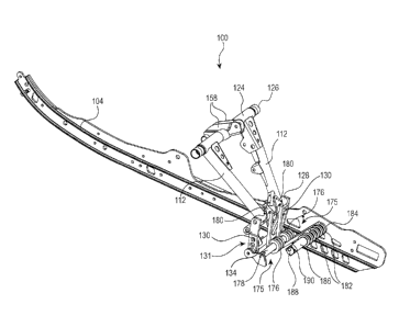
tunnel without substantially altering its orientation relative to the tunnel.
6210327.1
CA 02872570 2014-11-27
2
[0006] As both coupled and uncoupled rear suspension assemblies have
advantages, some
snowmobiles have a rear suspension assembly that acts like an uncoupled rear
suspension
assembly from a fully extended position of the rear suspension assembly to a
predetermined
intermediate position of the rear suspension assembly and acts like a coupled
rear suspension
assembly from the predetermined intermediate position of the rear suspension
assembly to a
fully compressed position of the rear suspension assembly. In some of these
rear suspension
assemblies, stoppers are provided such that a portion of the rear suspension
assembly abuts
these stoppers when the rear suspension assembly reaches the predetermined
intermediate
position as it moves toward the fully compressed position. When this happens,
the stoppers
reduce the degrees of freedom of movement of the rear suspension assembly
suddenly
changing the rear suspension assembly from being an uncoupled rear suspension
assembly to
being a coupled rear suspension assembly. United States Patent RE38,124,
reissued May 27,
2003, and United States Patent No. 6,206,124, issued March 27, 2001, the
entirety of both of
which is incorporated herein by reference, describe rear suspension assemblies
of this type.
However this sudden change can be felt by the driver and, if applicable, the
passenger(s) of
the snowmobile which can be a source of mild discomfort or annoyance. Also,
the impacts
with the stoppers require that some of the parts of the rear suspension
assembly need to be
large and robust enough to resist the repeated impacts.
[0007] There is therefore a need for a rear suspension assembly for a
snowmobile that can
vary the degree of coupling of the rear suspension assembly.
SUMMARY
[0008] It is an object of the present technology to ameliorate at least
some of the
inconveniences present in the prior art.
[0009] According to one implementation of the present technology, there is
provided a
snowmobile having a chassis including a tunnel having a longitudinal
direction, an engine
connected to the chassis, at least one ski connected to the chassis by a front
suspension, an
endless drive track disposed below the tunnel and operatively connected to the
engine for
propulsion of the snowmobile, and a rear suspension assembly supporting and
tensioning the
endless drive track. The rear suspension assembly has a fully extended
position and a fully
compressed position. The rear suspension assembly includes a front suspension
arm having
an upper end and a lower end, the upper end of the front suspension arm being
pivotally
6210327.1 =
CA 02872570 2014-11-27
3
connected to the tunnel, a rear suspension arm having an upper end and a lower
end, the
upper end of the rear suspension arm being pivotally connected to the tunnel,
a pair of slide
rails pivotally connected to the lower end of the front suspension arm and to
the lower end of
the rear suspension arm, at least one shock absorber connected between the
tunnel and the
pair of slide rails, the at least one shock absorber biasing the pair of slide
rails away from the
tunnel, and at least one suspension coupler coupling the rear suspension arm
with the front
suspension arm. The at least one suspension coupler generating a coupling
force to
continuously couple the front and rear suspension arms with each other during
a full range of
movement between the fully extended position and the fully compressed
position.
[0010] In some implementations of the present technology, the coupling
force increases as
the rear suspension assembly moves from the fully extended position to the
fully compressed
position.
[0011] In some implementations of the present technology, the coupling
force increases
progressively as the rear suspension assembly moves from the fully extended
position to the
fully compressed position.
[0012] In some implementations of the present technology, the coupling
force increases
linearly as the rear suspension assembly moves from the fully extended
position to the fully
compressed position.
[0013] In some implementations of the present technology, the at least one
suspension
coupler includes at least one torsion spring.
[0014] In some implementations of the present technology, the rear
suspension assembly
further includes a cross bar extending between the pair of slide rails. The at
least one torsion
spring is disposed around the cross bar and is pivotable around the cross bar.
[0015] In some implementations of the present technology, the cross bar is
a first cross
bar. A second cross bar extends between the pair of slide rails. The at least
one torsion
spring has a first end abutting the rear suspension arm and a second end
abutting the second
cross bar.
6210327.1
CA 02872570 2014-11-27
4
[0016] In some implementations of the present technology, the second cross
bar defines at
=
least one cam. The second end of the at least one torsion spring abuts the at
least one cam.
The at least one cam is movable to adjust a magnitude of the coupling force.
[0017] In some implementations of the present technology, the rear
suspension assembly
also includes a rocker arm having a first end pivotally connected to the lower
end of the rear
suspension arm and a second end pivotally connected to the pair of slide
rails. The at least
one suspension coupler biases the first end of the rocker arm toward a front
of the
snowmobile.
[0018] According to another implementation of the present technology,
there is provided a
rear suspension assembly for a snowmobile having a front suspension arm having
an upper
end and a lower end, a rear suspension arm having an upper end and a lower
end, a pair of
slide rails, at least one shock absorber, and at least one suspension coupler.
The upper end of
the front suspension arm is configured to be pivotally connected to a tunnel
of the
snowmobile. The upper end of the rear suspension arm is configured to be
pivotally
connected to the tunnel. The pair of slide rails is pivotally connected to the
lower end of the
front suspension arm and to the lower end of the rear suspension arm. The at
least one shock
absorber is configured to be connected to the tunnel and is connected to the
pair of slide rails.
The at least one shock absorber is configured to bias the pair of slide rails
away from the
tunnel. The at least one suspension coupler couples the rear suspension arm
with the front
suspension arm. The at least one suspension coupler generates a coupling force
to
continuously couple the front and rear suspension arms with each other during
a full range of
movement between the fully extended position and the fully compressed
position.
[0019] In some implementations of the present technology, the coupling
force increases as
the rear suspension assembly moves from the fully extended position to the
fully compressed
position.
[0020] In some implementations of the present technology, the coupling
force increases
progressively as the rear suspension assembly moves from the fully extended
position to the
fully compressed position.
[0021] In some implementations of the present technology, the coupling
force increases
linearly as the rear suspension assembly moves from the fully extended
position to the fully
compressed position.
6210327.1
CA 02872570 2014-11-27
[0022] In some implementations of the present technology, the at least one
suspension
coupler includes at least one torsion spring.
[0023] In some implementations of the present technology, a cross bar
extends between
the pair of slide rails. The at least one torsion spring is disposed around
the cross bar and is
5 pivotable around the cross bar.
[0024] In some implementations of the present technology, the cross bar is
a first cross
bar. The rear suspension assembly also has a second cross bar extending
between the pair of
slide rails. The at least one torsion spring has a first end abutting the rear
suspension arm and
a second end abutting the second cross bar.
[0025] In some implementations of the present technology, the second cross
bar defines at
least one cam. The second end of the at least one torsion spring abuts the at
least one cam.
The at least one cam is movable to adjust a magnitude of the coupling force.
[0026] In some implementations of the present technology, a rocker arm has
a first end
pivotally connected to the lower end of the rear suspension arm and a second
end pivotally
connected to the pair of slide rails. The at least one suspension coupler
biases the first end of
the rocker arm toward a front of the rear suspension assembly.
[0027] According to another aspect of the present technology, there is
provided a rear
suspension assembly for a snowmobile having a front suspension arm having an
upper end
and a lower end, a rear suspension arm having an upper end and a lower end, a
pair of slide
rails, at least one shock absorber, and at least one suspension coupler. The
upper end of the
front suspension arm is configured to be pivotally connected to a tunnel of
the snowmobile.
The upper end of the rear suspension arm is configured to be pivotally
connected to the
tunnel. The pair of slide rails is pivotally connected to the lower end of the
front suspension
arm and to the lower end of the rear suspension arm. The at least one shock
absorber is
configured to be connected to the tunnel and is connected to the pair of slide
rails. The at
least one shock absorber is configured to bias the pair of slide rails away
from the tunnel. At
least one suspension coupler couples the rear suspension arm with the front
suspension arm.
The at least one suspension coupler generates a coupling force to couple the
front and rear
suspension arms with each other at least at the fully extended position and
the fully
compressed position.
6210327.1
CA 02872570 2014-11-27
6
[0028] In an additional aspect, the coupling force increases as the rear
suspension
assembly moves from the fully extended position to the fully compressed
position.
[0029] In a further aspect, the coupling force increases progressively as
the rear
suspension assembly moves from the fully extended position to the fully
compressed
position.
[0030] In an additional aspect, the coupling force increases linearly as
the rear suspension
assembly moves from the fully extended position to the fully compressed
position.
[0031] In a further aspect, the at least one suspension coupler includes
at least one torsion
spring.
[0032] In an additional aspect, a cross bar extends between the pair of
slide rails. The at
least one torsion spring is disposed around the cross bar and is pivotable
around the cross bar.
[0033] . In a further aspect, the cross bar is a first cross bar. The rear
suspension assembly
also has a second cross bar extending between the pair of slide rails. The at
least one torsion
spring has a first end abutting the rear suspension arm and a second end
abutting the second
cross bar.
[0034] In an additional aspect, the second cross bar defines at least one
cam. The second
end of the at least one torsion spring abuts the at least one cam. The at
least one cam is
movable to adjust a magnitude of the coupling force.
[0035] In a further aspect, a rocker arm has a first end pivotally
connected to the lower
end of the rear suspension arm and a second end pivotally connected to the
pair of slide rails.
The at least one suspension coupler biases the first end of the rocker arm
toward a front of the
rear suspension assembly.
[0036] For purposes of this application, terms related to spatial
orientation such as
forwardly, rearward, upwardly, downwardly, left, and right, are as they would
normally be
understood by a driver of the vehicle sitting thereon in a normal riding
position. The
definitions of terms in the present application take precedence over the
definitions of the
same terms in documents incorporated herein by reference.
6210327.1
CA 02872570 2014-11-27
7
[0037] Implementations of the present technology each have at least one of
the above-
mentioned object and/or aspects, but do not necessarily have all of them. It
should be
understood that some aspects of the present technology that have resulted from
attempting to
attain the above-mentioned object may not satisfy this object and/or may
satisfy other objects
not specifically recited herein.
[0038] Additional and/or alternative features, aspects and advantages of
implementations
of the present technology will become apparent from the following description,
the
accompanying drawings and the appended claims.
BRIEF DESCRIPTION OF THE DRAWINGS
[0039] For a better understanding of the present technology, as well as
other aspects and
further features thereof, reference is made to the following description which
is to be used in
conjunction with the accompanying drawings, where:
[0040] Figure 1 is a left side elevation view of a snowmobile;
[0041] Figure 2 is a left side elevation view of a rear suspension
assembly of the
snowmobile of Fig. 1 in a fully extended position;
[0042] Figure 3 is a top plan view of the rear suspension assembly of Fig.
2;
[0043] Figure 4 is a cross-sectional view of the rear suspension assembly
of Fig. 2 taken
through line 4-4 of Fig. 3;
[0044] Figure 5 is a perspective view taken from a rear, left side of some
components of
the rear suspension assembly of Fig. 2;
[0045] Figure 6 is a left side elevation view of the rear suspension
assembly of Fig. 2 in a
partially compressed position, with a left slide rail and some other
components removed for
clarity;
[0046] Figure 7 is a left side elevation view of the rear suspension
assembly of Fig. 2 in a
fully compressed position, with the left slide rail and some other components
removed for
clarity;
6210327.1
CA 02872570 2014-11-27
[0047] Figure S is a perspective view taken from a rear, left side of some
components of
an alternative implementation of the rear suspension assembly of Fig. 2; and
[0048] Figure 9 is a perspective view taken from a rear, left side of some
components of a
portion of another alternative implementation of the rear suspension assembly
of Fig. 2.
DETAILED DESCRIPTION
[0049] A snowmobile 10, shown in Fig. 1, has a front end 12 and a rear end
14 that are
defined consistently with the forward travel direction of the vehicle. The
snowmobile 10
includes a chassis 16 that includes a tunnel 18, an engine cradle portion 20
and a front
suspension assembly portion 22. An engine 24, which is schematically
illustrated in Fig. 1, is
supported by the engine cradle portion 20 of the chassis 16. Two skis 26 (only
the left one of
which is shown) are positioned at the front end 12 of the snowmobile 10 and
are attached to
the front suspension assembly portion 22 of the chassis 16 through front
suspension
assemblies 28. Each front suspension assembly 28 includes a ski leg 30, a pair
of A-arms 32,
and a shock absorber 34. Tie rods 35 connect the ski legs 30 to a steering
column 36 or an
assembly of multiple steering columns. A handlebar 38 is connected to a top of
the steering
column 36 and is used to steer the skis 26 through the steering column 36, tie
rods, and ski
legs 30.
[0050] An endless drive track 40 is disposed under the tunnel 18. The
endless drive track
40 is operatively connected to the engine 24 through a belt transmission
system (not shown),
such as a continuously variable transmission (CVT), and a reduction drive (not
shown). The
endless drive track 40 is driven to run about a rear suspension assembly 100
for propelling
the snowmobile 10. The rear suspension assembly 100 will be described in
greater detail
below.
[0051] Fairings 42 connected to the front of the chassis 16 provide an
external shell that
protects the engine 24 and its associated components. The fairings 42 include
a hood 44 and
side panels 46 that can be opened to allow access to the engine 24 and its
associated
components when this is required, for inspection or maintenance for example. A
windshield
48 is connected to the fairings 42 forward of the handlebar 38. Alternatively,
the windshield
48 could be attached directly to the handlebar 38. The windshield 48 acts as a
windscreen to
lessen the force of the air on the driver while the snowmobile 10 is moving.
6210327.1
CA 02872570 2014-11-27
9
[0052] A fuel tank 50 is disposed on top of the tunnel 18. A straddle seat
52 is disposed
on top of the fuel tank 50. It is contemplated that the straddle seat 52 could
be disposed
directly on top of the tunnel 18. The straddle seat 52 is configured to
receive only a driver
thereon. It is contemplated that the straddle seat 52 could be longer in order
to also receive
one or more passengers thereon. It is also contemplated that another straddle
seat could be
disposed on the tunnel 18 behind the straddle seat 52 to receive one or more
passengers
thereon. Two foot rests 54 are positioned on opposite sides of the snowmobile
10 below the
straddle seat 52 to accommodate the driver's feet.
[0053] Turning now to Figs. 2 to 7, the rear suspension assembly 100 will
be described in
more detail. The endless drive track 40 is suspended for movement relative to
the chassis 16
and is tensioned by the rear suspension assembly 100. The rear suspension
assembly 100 is
movable between a fully extended position shown in Figs. 2 to 5 and a fully
compressed
position shown in Fig. 7. Fig. 6 illustrates one possible position
intermediate the fully
extended and the fully compressed positions.
[0054] The rear suspension assembly 100 has a slide frame assembly 102. The
slide
frame assembly 102 includes a pair of spaced apart slide rails 104 that engage
the inner side
of the ground-engaging portion of the endless drive track 40. A plurality of
rollers 106 (only
some of which are illustrated) are rotationally supported by the slide frame
assembly 102.
Other rollers 108 are rotationally connected to the tunnel 18. The rollers
106, 108 and the
slide rails 104 define the path over which the endless drive track 40 travels.
[0055] The rear suspension assembly 100 has left and right front
suspension arms 110 and
left and right rear suspension arms 112. It is contemplated that the rear
suspension assembly
100 could have only a single front suspension arm 110. It is also contemplated
that the rear
suspension assembly 100 could have only a single rear suspension arm 112.
[0056] As can be seen in Figs. 1 to 4, the front suspension arms 110 extend
downwardly
and rearward from a front portion of the tunnel 18. The upper ends of the
front suspension
arms 110 are connected to a shaft 114 that is pivotally attached to the tunnel
18 about a pivot
axis 116. The lower ends of the front suspension arms 110 are each pivotally
attached to
their respective slide rails 104 about a pivot axis 118. A cross-member 120
extends between
the front suspension arms 110. In the present implementation, the cross-member
120 is
welded to the front suspension arms 110, but it is contemplated that they
could be connected
6210327.
CA 02872570 2014-11-27
to each other by other means. The front suspension arms 110 and the cross-
member 120 are
made of metal tubes having generally circular cross-sections. It is
contemplated that the front
suspension arms 110 and the cross-member 120 could have other shapes of cross-
sections,
and that the front suspension arms 110 and the cross-member 120 could be made
of a
5 material other than metal.
[0057] As can be seen in Figs. 1 to 5, the rear suspension arms 112 extend
downwardly
and rearward from the tunnel 18, and are disposed rearward of the front
suspension arms 110.
The rear suspension arms 112 are made of metal tubes having generally circular
cross-
sections. It is contemplated that the rear suspension arms 112 could have
other shapes of
10 cross-sections, and that the rear suspension arms 112 could be made of a
material other than
metal. The rear suspension arms 112 are pivotally attached to the tunnel 18
about a pivot axis
122 by a tube and shaft assembly. The tube and shaft assembly includes a tube
124 rotatably
supported by a shaft 126 that is mounted at both ends thereof to the tunnel
18. The tube 124
supports the rollers 108. The upper ends of the rear suspension arms 112 are
connected to the
shaft 126. The lower ends of the rear suspension arms 112 are fixedly
connected to a cross
bar 128 (Fig. 5). The cross bar 128 is pivotally connected to left and right
arms 130 about a
pivot axis 132. The arms 130 together form a rocker arm 131. Each of the left
and right arms
130 is connected at its lower end to another cross bar 134 (Fig. 5). The cross
bar 134 is
pivotally connected between the slide rails 102 about a pivot axis 136.
[0058] A rear shock absorber 138 is connected between the front suspension
arms 110 and
the rear suspension arms 112, as it will be described in greater details
below. As can be seen
in Figs. 1 to 4, a front shock absorber assembly 140 disposed between the
tunnel 18 and the
slide frame assembly 102 extends rearward and downwardly from the front
portion of the
tunnel 18. The front shock absorber assembly 140 is disposed partially forward
of the front
suspension arms 110. A lower end of the shock absorber assembly 140 is
disposed forward
of the lower ends of the front suspension arms 110. The front shock absorber
assembly 140
is a damping unit which includes a hydraulic damper and a coil spring for
absorbing the
impact energy when impact forces are applied to the opposite ends of the
damping unit. The
coil spring biases the damping unit toward an extended position so that the
hydraulic damper
is in position to absorb the impact energies. Since shock absorber assemblies
of the type of
the shock absorber assembly 140 are well known in the art, it will not be
further described
herein.
6210327.1
CA 02872570 2014-11-27
11
[0059] The front shock absorber assembly 140 is pivotally connected to
brackets 142
about a pivot axis 144. The brackets 142 are fixedly connected, by welding for
example, to a
shaft 146. U-shaped brackets 148 are disposed at both ends of the shaft 146
and receive the
end portions of the shaft 114 therein. As a result, the upper end of the front
shock absorber
assembly 140 is pivotally connected to the tunnel 18. The front shock absorber
assembly 140
is pivotally connected at a lower end thereof to a shaft 150 about a pivot
axis 152. The shaft
150 extends between and is fixedly connected to the left and right slide rails
104. The front
shock absorber assembly 140 is configured to rotate about the shaft 150.
[0060] As can be seen in Figs. 1 to 4, the rear shock absorber 138 extends
forwardly and
downwardly from its upper end, and is disposed at least in part rearward of
the front
suspension arms 110. The rear shock absorber 138 includes a hydraulic damper
that is well
known in the art, and will therefore not be described in detail herein. The
rear shock absorber
138 is operatively connected at its upper end to the tunnel 18 by being
pivotally connected to
the rear brackets 154 (Fig. 4) mounted on the tube 124 about a pivot axis 156.
The rear
brackets 154 are fixedly connected to the tube 124.
[0061] The lower end of the rear shock absorber 138 is pivotally connected
to the front
suspension arms 110 via the cross-member 120, left and right bracket arms 158
and left and
right links 160. One end of each of the left and right bracket arms 158 is
fixedly connected to
the cross-member 120. The opposite end of each of the left and right bracket
arms 158 is
pivotally connected to an end of a corresponding one of the left and right
links 160. The
opposite ends of the left and right links 160 are pivotally connected to the
lower end of the
rear shock absorber 138 about a pivot axis 162. The lower end of the rear
shock absorber 138
is disposed laterally between the links 160.
[0062] Tie rods 164 are disposed on each side of the rear shock absorber
196. A lower
end of each of the left and right tie rods 164 is pivotally connected to a
corresponding one of
the left and right links 160 about the pivot axis 162. An upper end of each of
the left and
right tie rods 164 is pivotally connected to the rear brackets 154 about a
pivot axis 166. As
can be seen in Fig. 4, the pivot axes 156 and 166 are disposed on opposite
sides of the pivot
axis 122 when the rear suspension assembly 100 is in the fully extended
position.
[0063] Left and right torsion springs 168 are provided in order to push the
slide frame
assembly 102 away from the tunnel 18, and to maintain the rear shock absorber
138 and the
6210327.1
CA 02872570 2014-11-27
12
front shock absorber assembly 140 substantially extended when no substantial
loads are
applied thereon. The left and right torsion springs 168 surround an
intermediate shaft 170
(Fig. 4). A rear free end of each of the torsion springs 168 abuts a rotatable
cam 172
disposed on an intermediate shaft 174. A front free end of each torsion spring
168 is slidably
connected to a corresponding slide rail 104. Turning the cam 172 adjusts an
amount of
preloading of the torsion springs 168. The torsion forces of the springs 168
bias the rear
suspension arms 112 such that the rear suspension arms 112 tends to pivot away
from the
tunnel 18 about the shaft 126 (i.e. in the clockwise direction with respect to
Fig. 2). It is
contemplated that only one torsion spring 168 could be used.
[0064] Left and right flexible tension straps 170 are attached at their
upper ends to the
shaft 146, and are attached at their lower ends to the slide frame assembly
102 by a cross bar
173. The cross bar 173 extends between and is attached at its opposite ends to
the front ends
of the slide rails 102. The flexible tension straps 170 prevent the slide
frame assembly 102
from being pushed too far away from the tunnel 18.
[0065] As best seen in Fig. 5, a pair of suspension couplers 175 is
provided rearward of
the rocker arm 131. It is contemplated that only one or more than two
suspension couplers
175 could be provided. Each suspension coupler 175 includes a torsion spring
176 disposed
around a cross bar 178 disposed between and connected to the slide rails 104.
The cross bar
178 is disposed rearward of the cross bar 134 and of the pivot axis 136 of the
arms 130. The
torsions springs 176 are disposed side by side on the cross bar 178. The
torsion springs can
pivot about the cross bar 178. One end portion of each torsion spring 176
abuts the cross bar
128. Two U-shaped plates 180 are connected to the cross bar 128. The ends
portions of the
torsion springs 176 are received in corresponding slots defined in the U-
shaped plates 180.
As a result, the U-shaped plates 180 help prevent lateral movement of the
springs 176. It is
contemplated that instead of having slots extending therethrough, that the U-
shaped plates
180 could be made of a relatively soft material, such as plastic, and have
recesses defined
therein to receive the portions of the springs 176. As a result, when the U-
shaped plates 180
are worn, they can be easily replaced. It is contemplated that the U-shape
plates 180 could be
omitted and that recesses could be defined in the cross bar 128 to receive the
portions of the
springs 176.
[0066] The other end portion of each torsion spring 176 is received in a
corresponding
channel 182 defined by a cam 184. The cam 184 is defined by a hollow cross bar
186. It is
6210327.1
CA 02872570 2014-11-27
13
contemplated that the cam 184 could be a part separate from the cross bar 186
and connected
to the cross bar 186. The cross bar 186 is disposed eccentrically around a
shaft 188 and can
be rotated about the shaft 188. The shaft 188 is disposed between and is
connected to the
slide rails 104. As can be seen, the shaft 188 is disposed rearward of and
vertically higher
than the cross bar 178. A square insert 190 is fixed to an end of the cross
bar 186. By
turning the cam 184, the amount of preloading in the torsion springs 176 can
be modified. To
turn the cam 184, a tool, such as wrench, is used to engage and turn the
square insert, which
as a result turns the cross bar 186 and therefore the cam 184. It is
contemplated that the insert
190 could have another shape, such as hexagonal for example. It is also
contemplated that
the insert 190 could be omitted and that a feature similar to the insert 190
could be provided
directly on the cam 184. It is also contemplate that the cross bar 186
defining the cam 184
and the insert 190 could be omitted. In such an implementation, the torsion
springs 176
would abut the shaft 188 directly. It is contemplated that in such an
implementation, U-
shaped plates having slots similar to the plates 180 described above could be
connected on
the shaft 188 to receive the portions of the torsion springs 176 therein.
[0067] The suspension couplers 175 generate a coupling force that
continuously couples
the front suspension arms 110 and the rear suspension arms 112 with each other
during a full
range of movement of the rear suspension 100 between the fully extended
position (Figs 2 to
5) and the fully compressed position (Fig. 7). As can be seen by comparing
Figs. 5 (fully
extended position), 6 (intermediate position), and 7 (fully compressed), as
the rear suspension
100 gets compressed, the arms 130 pivot about the pivot axis 136. As the arms
130 pivot
about the pivot axis 136, the cross-bar 128 moves rearward and downward and
causes the
front and rear ends of the torsion springs 176 to get compressed toward each
other. As a
result, the amount of torsion in the torsion springs 176 increases which
results in an increase
in the coupling force generated by the suspension couplers 175. The coupling
force
generated by the suspension couplers 175 has its greatest magnitude in the
fully compressed
position of the rear suspension assembly 100 and its smallest magnitude in the
fully extended
position. In the present implementation, the coupling force generated by the
suspension
couplers 175 increases progressively and linearly as the rear suspension
assembly 100 moves
from the fully extended position to the fully compressed position. The
suspension couplers
175 bias the cross bar 128, and therefore the rocker arm 130, toward a front
of the
snowmobile 10. By turning the cam 184, the magnitude of the coupling force
generated by
the suspension couplers 175 can be modified. As the coupling force generated
by the
6210327.1
CA 02872570 2014-11-27
14
suspension couplers 175 increases, the front suspension arms 110 and the rear
suspension
arms 112 move less independently from each other.
[00681 Other implementations of suspension couplers that progressively
increase the
coupling force as the rear suspension assembly is compressed are contemplated.
For
example, the torsion springs 176 could be replaced by coil springs connected
between the
cross bar 128 and the cross bar 178.
.=
[00691 Fig. 8 illustrates parts of a rear suspension assembly 200 having
a suspension
coupler 202 that is another alternative implementation of the suspension
coupler 175. Other
than the suspension coupler 202 and some of the elements described below, the
suspension
assembly 200 is the same as the suspension assembly 100 and, where applicable,
the elements
of the suspension assembly 200 that are the same as those of the suspension
assembly 100
have been labeled with the same reference numerals.. In the suspension
assembly 200, a cross
bar 204 extends between and is connected to the arms 130. The cross bar 204 is
disposed
between the cross bar 128 and the cross bar 134. Legs 206 are connected
between the cross
bar 204 and the cross bar 128. It is contemplated that the legs 206 could be
omitted. A
sleeve 208 is disposed around the cross bar 128 between the legs 206. It is
contemplated that
the sleeve 208 could be omitted. The suspension coupler 202 has a torsion
spring 210
disposed around and pivotable about the sleeve 208. One end portion of the
torsion spring
210 abuts the cross bar 204. It is contemplated that U-shaped plates similar
to the plates 180
described above could be provided on the cross bar 204. The other end portion
of the torsion
spring 210 abuts the cam 184. As can be seen, the shaft 188 is disposed
vertically lower in
the suspension assembly 200 than in the suspension assembly 100. As in the
rear suspension
assembly 100, the cam 184 can be turned to change the magnitude of the
coupling force
generated by the suspension coupler 202. It is contemplated that the cam 184
could be
omitted. Like the suspension couplers 175 of the suspension assembly 100, the
suspension
coupler 202 generates a coupling force that continuously couples the front
suspension arms
110 and the rear suspension arms 112 with each other during a full range of
movement of the
rear suspension 200 between the fully extended position and the fully
compressed position,
and the coupling force generated by the suspension coupler 202 increases
progressively and
linearly as the rear suspension assembly 200 moves from the fully extended
position to the
fully compressed position.
6210327.1
CA 02872570 2014-11-27
[0070] Fig. 9 illustrates parts of a rear suspension assembly 300 having
suspension
couplers 302, 304 that are other alternative implementations of the suspension
coupler 175.
Other than the suspension couplers 302 and some of the elements described
below, the
suspension assembly 300 is the same as the suspension assembly 100 and, where
applicable,
5 the elements of the suspension assembly 300 that are the same as those of
the suspension
assembly 100 have been labeled with the same reference numerals. In the
suspension
assembly 300, the hollow cross bar 186, the cams 184 and the square insert 190
have been
removed.
[0071] The suspension coupler 302 includes a torsion spring 176A disposed
around the
10 cross bar 178. The torsion spring 176A can pivot about the cross bar
178. One end portion
of the torsion spring 176A abuts the cross bar 128. The end portion of the
torsion spring
176A is received in the slot defined in one of the U-shaped plates 180. The
other end portion
of the torsion spring 176A abuts the shaft 188. Like the suspension couplers
175 of the
suspension assembly 100, the suspension coupler .302 generates a coupling
force that
15 continuously couples the front suspension arms 110 and the rear
suspension arms 112 with
each other during a full range of movement of the rear suspension 300 between
the fully
extended position and the fully compressed position.
[0072] The suspension coupler 304 includes a torsion spring 176B disposed
around the
cross bar 178 next to the torsion spring 176A. The torsion spring 176B can
pivot about the
cross bar 178. In the fully extended position of the suspension assembly 300,
the end portion
306 of the torsion spring 176B abuts the shaft 188 and the end portion 308 of
the torsion
spring 176B is spaced from the cross bar 128. Unlike the suspension couplers
175 of the
suspension assembly 100, the suspension coupler 304 only generates a coupling
force that
couples the front suspension arms 110 and the rear suspension arms 112 with
each other once
the rear suspension 300 has been sufficiently compressed for the cross bar 128
to make
contact with the end portion 308 of the torsion spring 176B. Between this
position and the
fully compressed position, the suspension coupler 304 generates a coupling
force that
continuously couples the front suspension arms 110 and the rear suspension
arms 112 with
each other.
[0073] As a result of the suspension coupler 304 only generating a coupling
force for a
portion of the full range of movement of the rear suspension 300 between the
fully extended
position and the fully compressed position, the combined coupling force
generated by the
6210327.1
CA 02872570 2014-11-27
16
suspension couplers 302 and 304 increases progressively, but not linearly, as
the rear
suspension assembly 300 moves from the fully extended position to the fully
compressed
position. The combined coupling force will be linear over certain ranges of
positions, but
there will be a transition between these ranges as the cross bar 128 makes
contact with the
end portion 308 of the torsion spring 176B of the suspension coupler 304.
[0074] Modifications and improvements to the above-described
implementations of the
present technology may become apparent to those skilled in the art. The
foregoing
description is intended to be exemplary rather than limiting. The scope of the
present
technology is therefore intended to be limited solely by the scope of the
appended claims.
6210327.1