Note: Descriptions are shown in the official language in which they were submitted.
CA 02872672 2016-04-19
DISINTEGRABLE TUBULAR ANCHORING SYSTEM AND METHOD OF USING
THE SAME
BACKGROUND
[0001) Downhole constructions including oil and natural gas wells, CO2
sequestration
boreholes, etc. often utilize borehole components or tools that, due to their
function, are only
required to have limited service lives that are considerably less than the
service life of the well.
After a component or tool service function is complete, it must be removed or
disposed of in
order to recover the original size of the fluid pathway for use, including
hydrocarbon
production, CO2 capture or sequestration, etc. Disposal of components or tools
can be
accomplished by milling or drilling the component or tool out of the borehole,
which is
generally a time consuming and expensive operation. The industry is always
receptive to new
systems, materials, and methods that eliminate removal of a component or tool
from a borehole
without such milling and drilling operations.
BRIEF DESCRIPTION
[0002] Disclosed herein is a disintegrable tubular anchoring system that
comprises a
frustoconical member; a sleeve with at least one first surface being radially
alterable in
response to longitudinal movement of the frustoconical member relative to the
sleeve, the at
least one first surface being engagable with a wall of a structure positioned
radially thereof to
maintain position of at least the sleeve relative to the structure when
engaged therewith; a seal
with at least one second surface being radially alterable in response to
longitudinal movement
of the frustoconical member relative to the seal; and a seat in operable
communication with the
frustoconical member having a land being sealingly engagable with a removable
plug runnable
thereagainst, the land being longitudinally displaced relative to the sleeve
in an upstream
direction defined by direction of flow that urges the plug thereagainst,
wherein the
frustoconical member, sleeve, seal, and seat are disintegrable and
independently comprise a
metal composite which includes a cellular nanomatrix comprising a metallic
nanomatrix
material; and a metal matrix disposed in the cellular nanomatrix.
[0003] Further disclosed is a process of isolating a structure, the process
comprising:
disposing the disintegrable tubular anchoring system in the structure;
radially altering the
sleeve to engage a surface of the structure; and radially altering the seal to
the isolate the
structure.
1
CA 02872672 2016-04-19
[0004] Further disclosed is a disintegrable tubular anchoring system
comprising: a
frustoconical member; a sleeve to engage a first portion of the frustoconical
member; a seal to
engage a second portion of the frustoconical member; and a seat in operable
communication
with the frustoconical member, wherein the frustoconical member, sleeve, seal,
and seat are
disintegrable and independently comprise a metal composite which includes: a
cellular
nanomatrix comprising a metallic nanomatrix material; and a metal matrix
disposed in the
cellular nanomatrix.
[0004a] Further disclosed is a disintegrable tubular anchoring system
comprising: a
frustoconical member; a sleeve to engage a first portion of the frustoconical
member; a seal to
engage a second portion of the frustoconical member; and a seat in operable
communication
with the frustoconical member, wherein the frustoconical member, sleeve, seal,
and seat are
disintegrable and independently comprise a metal composite which includes: a
cellular
nanomatrix comprising a metallic nanomatrix material; and a metal matrix
disposed in the
cellular nanomatrix, wherein the sleeve comprises a first surface which is
radially alterable in
response to longitudinal movement of the frustoconical member relative to the
sleeve, the first
surface being engagable with a wall of a structure positioned radially thereof
to maintain
position of at least the sleeve relative to the structure when engaged
therewith, wherein the seal
comprises a second surface which is radially alterable in response to
longitudinal movement of
the frustoconical member relative to the seal, and wherein the seat comprises
a land which is
sealingly engagable with a removable plug runnable thereagainst, the land
being longitudinally
displaced relative to the sleeve in an upstream direction defined by direction
of flow that urges
the plug thereagainst.
[0004b] Further disclosed is a disintegrable tubular anchoring system
comprising: a
frustoconical member; a sleeve to engage a first portion of the frustoconical
member; a seal to
engage a second portion of the frustoconical member; and a seat in operable
communication
with the frustoconical member, wherein the frustoconical member, sleeve, seal,
and seat are
disintegrable and independently comprise a metal composite which includes: a
cellular
nanomatrix comprising a metallic nanomatrix material; a metal matrix disposed
in the cellular
nanomatrix; and a disintegrating agent or a strengthening agent.
2
CA 02872672 2016-04-19
BRIEF DESCRIPTION OF THE DRAWINGS
[0005] The following descriptions should not be considered limiting in any
way. With
reference to the accompanying drawings, like elements are numbered alike:
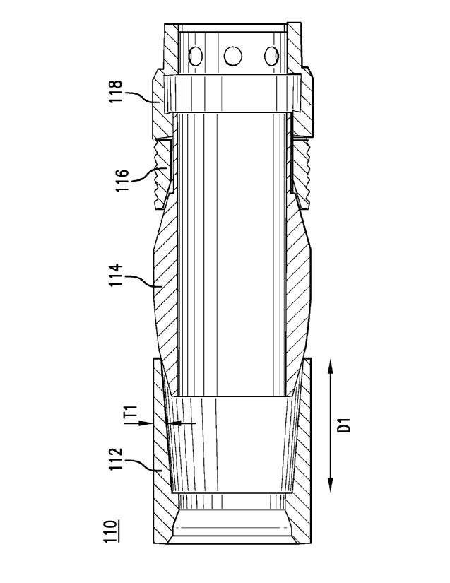
[0006] FIG. 1 depicts a cross sectional view of a disintegrable tubular
anchoring
system;
[0007] FIG. 2 depicts a cross sectional view of a disintegrable metal
composite;
[0008] FIG. 3 is a photomicrograph of an exemplary embodiment of a
disintegrable
metal composite as disclosed herein;
[0009] FIG. 4 depicts a cross sectional view of a composition used to make the
disintegrable metal composite shown in FIG. 2;
[0010] FIG. 5 A is a photomicrograph of a pure metal without a cellular
nanomatrix;
[0011] FIG. 5B is a photomicrograph of a disintegrable metal composite with a
metal
matrix and cellular nanomatrix;
[0012] FIG. 6 is a graph of mass loss versus time for various disintegrable
metal
composites that include a cellular nanomatrix indicating selectively
tailorable disintegration
rates;
[0013] FIG. 7A is an electron photomicrograph of a fracture surface of a
compact
formed from a pure Mg powder;
[0014] FIG. 7B is an electron photomicrograph of a fracture surface of an
exemplary
embodiment of a disintegrable metal composite with a cellular nanomatrix as
described herein;
2a
CA 02872672 2014-11-04
WO 2013/169416 PCT/US2013/035258
[0018] FIG. 10 depicts a cross sectional view of a disintegrable frustoconical
member;
[0019] FIG. 11 depicts a cross sectional view of a disintegrable bottom sub;
[0020] FIGS. 12A, 12B, and 12C respectively depict a perspective view, cross
sectional view, and a top view of a disintegrable sleeve;
[0021] FIGS. 13A and 13B respectively depict a perspective view and cross
sectional
view of a disintegrable seal;
[0022] FIG. 14 depicts a cross sectional view of another embodiment of a
disintegrable tubular anchoring system;
[0023] FIG. 15 depicts a cross sectional view of the disintegrable tubular
anchoring
system of FIG. 14 in a set position;
[0024] FIG. 16 depicts a cross sectional view of another embodiment of a
disintegrable tubular anchoring system;
[0025] FIG. 17 depicts a cross sectional view of another embodiment of a
disintegrable seal with an elastomer backup ring in a disintegrable tubular
anchoring system;
and
[0026] FIGS. 18A and 18B respectively depict a cross sectional and perspective
views of another embodiment of a disintegrable seal.
DETAILED DESCRIPTION
[0027] A detailed description of one or more embodiments of the disclosed
apparatus
and method are presented herein by way of exemplification and not limitation
with reference
to the Figures.
[0028] The inventors have discovered that a high strength, high ductility yet
fully
disintegrable tubular anchoring system can be made from materials that
selectively and
controllably disintegrate in response to contact with certain downhole fluids
or in response to
changed conditions. Such a disintegrable system includes components that are
selectively
corrodible and have selectively tailorable disintegration rates and
selectively tailorable
material properties. Additionally, the disintegrable system has components
that have varying
compression and tensile strengths and that include a seal (to form, e.g., a
conformable metal-
to-metal seal), cone, deformable sleeve (or slips), and bottom sub. As used
herein,
"disintegrable" refers to a material or component that is consumable,
corrodible, degradable,
dissolvable, weakenable, or otherwise removable. It is to be understood that
use herein of the
3
CA 02872672 2016-04-19
=
term "disintegrate," or any of its forms (e.g., "disintegration"),
incorporates the stated meaning.
[0029] An embodiment of a disintegrable tubular anchoring system is show in
FIG. 1.
The disintegrable tubular anchoring system 110 includes a seal 112,
frustoconical member 114,
a sleeve 116 (shown herein as a slip ring), and a bottom sub 118. The system
110 is configured
such that longitudinal movement of the frustoconical member 114 relative to
the sleeve 116 and
relative to the seal 112 causes the sleeve 116 and seal 112 respectively to be
radially altered.
Although in this embodiment the radial alterations are in radially outward
directions, in
alternate embodiments the radial alterations could be in other directions such
as radially
- inward. Additionally, a longitudinal dimension D1 and thickness TI of a wall
portion of the seal
112 can be altered upon application of a compressive force thereto. The seal
112, frustoconical
member 114, sleeve 116, and bottom sub 118 (i.e., components of the system
110) are
disintegrable and contain a metal composite. The metal composite includes a
metal matrix
disposed in a cellular nanomatrix and a disintegration agent.
[0030] In an embodiment, the disintegration agent is disposed in the metal
matrix. In
another embodiment, the disintegration agent is disposed external to the metal
matrix. In yet
another embodiment, the disintegration agent is disposed in the metal matrix
as well as external
to the metal matrix. The metal composite also includes the cellular nanomatrix
that comprises
a metallic nanomatrix material. The disintegration agent can be disposed in
the cellular
nanomatrix among the metallic nanomatrix material. An exemplary metal
composite and
method used to make the metal composite are disclosed in U.S. Patent
Application Serial
Numbers 12/633,682, 12/633,688, 13/220,832, 13/220,822, and 13/358,307.
[0031] The metal composite is, for example, a powder compact as shown in FIG.
2.
The metal composite 200 includes a cellular nanomatrix 216 comprising a
nanomatrix material
220 and a metal matrix 214 (e.g., a plurality of dispersed particles)
comprising a particle core
material 218 dispersed in the cellular nanomatrix 216. The particle core
material 218
comprises a nano structured material. Such a metal composite having the
cellular nanomatrix
with metal matrix disposed therein is referred to as controlled electrolytic
material.
[0032] With reference to FIGS. 2 and 4, metal matrix 214 can include any
suitable
metallic particle core material 218 that includes nanostructure as described
herein. In an
exemplary embodiment, the metal matrix 214 is formed from particle cores 14
(FIG. 4) and can
include an element such as aluminum, iron, magnesium, manganese, zinc, or a
4
CA 02872672 2014-11-04
WO 2013/169416 PCT/US2013/035258
combination thereof, as the nanostructured particle core material 218. More
particularly, in
an exemplary embodiment, the metal matrix 214 and particle core material 218
can include
various Al or Mg alloys as the nanostructured particle core material 218,
including various
precipitation hardenable alloys Al or Mg alloys. In some embodiments, the
particle core
material 218 includes magnesium and aluminum where the aluminum is present in
an amount
of about 1 weight percent (wt%) to about 15 wt%, specifically about 1 wt% to
about 10 wt%,
and more specifically about 1 wt% to about 5 wt%, based on the weight of the
metal matrix,
the balance of the weight being magnesium.
[0033] In an additional embodiment, precipitation hardenable Al or Mg alloys
are
particularly useful because they can strengthen the metal matrix 214 through
both
nanostructuring and precipitation hardening through the incorporation of
particle precipitates
as described herein. The metal matrix 214 and particle core material 218 also
can include a
rare earth element, or a combination of rare earth elements. Exemplary rare
earth elements
include Sc, Y, La, Ce, Pr, Nd, or Er. A combination comprising at least one of
the foregoing
rare earth elements can be used. Where present, the rare earth element can be
present in an
amount of about 5 wt% or less, and specifically about 2 wt% or less, based on
the weight of
the metal composite.
[0034] The metal matrix 214 and particle core material 218 also can include a
nanostructured material 215. In an exemplary embodiment, the nanostructured
material 215
is a material having a grain size (e.g., a subgrain or crystallite size) that
is less than about 200
nanometers (nm), specifically about 10 nm to about 200 nm, and more
specifically an average
grain size less than about 100 nm. The nanostructure of the metal matrix 214
can include
high angle boundaries 227, which are usually used to define the grain size, or
low angle
boundaries 229 that may occur as substructure within a particular grain, which
are sometimes
used to define a crystallite size, or a combination thereof. It will be
appreciated that the
nanocellular matrix 216 and grain structure (nanostructured material 215
including grain
boundaries 227 and 229) of the metal matrix 214 are distinct features of the
metal composite
200. Particularly, nanocellular matrix 216 is not part of a crystalline or
amorphous portion of
the metal matrix 214.
[0035] The disintegration agent is included in the metal composite 200 to
control the
disintegration rate of the metal composite 200. The disintegration agent can
be disposed in
the metal matrix 214, the cellular nanomatrix 216, or a combination thereof
According to an
embodiment, the disintegration agent includes a metal, fatty acid, ceramic
particle, or a
combination comprising at least one of the foregoing, the disintegration agent
being disposed
CA 02872672 2014-11-04
WO 2013/169416 PCT/US2013/035258
among the controlled electrolytic material to change the disintegration rate
of the controlled
electrolytic material. In one embodiment, the disintegration agent is disposed
in the cellular
nanomatrix external to the metal matrix. In a non-limiting embodiment, the
disintegration
agent increases the disintegration rate of the metal composite 200. In another
embodiment,
the disintegration agent decreases the disintegration rate of the metal
composite 200. The
disintegration agent can be a metal including cobalt, copper, iron, nickel,
tungsten, zinc, or a
combination comprising at least one of the foregoing. In a further embodiment,
the
disintegration agent is the fatty acid, e.g., fatty acids having 6 to 40
carbon atoms.
Exemplary fatty acids include oleic acid, stearic acid, lauric acid,
hyroxystearic acid, behenic
acid, arachidonic acid, linoleic acid, linolenic acid, recinoleic acid,
palmitic acid, montanic
acid, or a combination comprising at least one of the foregoing. In yet
another embodiment,
the disintegration agent is ceramic particles such as boron nitride, tungsten
carbide, tantalum
carbide, titanium carbide, niobium carbide, zirconium carbide, boron carbide,
hafnium
carbide, silicon carbide, niobium boron carbide, aluminum nitride, titanium
nitride, zirconium
nitride, tantalum nitride, or a combination comprising at least one of the
foregoing.
Additionally, the ceramic particle can be one of the ceramic materials
discussed below with
regard to the strengthening agent. Such ceramic particles have a size of 5 gm
or less,
specifically 2 gm or less, and more specifically 1 gm or less. The
disintegration agent can be
present in an amount effective to cause disintegration of the metal composite
200 at a desired
disintegration rate, specifically about 0.25 wt% to about 15 wt%, specifically
about 0.25 wt%
to about 10 wt%, specifically about 0.25 wt% to about 1 wt%, based on the
weight of the
metal composite.
[0036] In an exemplary embodiment, the cellular nanomatrix 216 includes
aluminum,
cobalt, copper, iron, magnesium, nickel, silicon, tungsten, zinc, an oxide
thereof, a nitride
thereof, a carbide thereof, an intermetallic compound thereof, a cermet
thereof, or a
combination comprising at least one of the foregoing. The metal matrix can be
present in an
amount from about 50 wt% to about 95 wt%, specifically about 60 wt% to about
95 wt%, and
more specifically about 70 wt% to about 95 wt%, based on the weight of the
seal. Further,
the amount of the metal nanomatrix material is about 10 wt% to about 50 wt%,
specifically
about 20 wt% to about 50 wt%, and more specifically about 30 wt% to about 50
wt%, based
on the weight of the seal.
[0037] In another embodiment, the metal composite includes a second particle.
As
illustrated generally in FIGS. 2 and 4, the metal composite 200 can be formed
using a coated
metallic powder 10 and an additional or second powder 30, i.e., both powders
10 and 30 can
6
CA 02872672 2014-11-04
WO 2013/169416 PCT/US2013/035258
have substantially the same particulate structure without having identical
chemical
compounds. The use of an additional powder 30 provides a metal composite 200
that also
includes a plurality of dispersed second particles 234, as described herein,
that are dispersed
within the cellular nanomatrix 216 and are also dispersed with respect to the
metal matrix
214. Thus, the dispersed second particles 234 are derived from second powder
particles 32
disposed in the powder 10, 30. In an exemplary embodiment, the dispersed
second particles
234 include Ni, Fe, Cu, Co, W, Al, Zn, Mn, Si, an oxide thereof, nitride
thereof, carbide
thereof, intermetallic compound thereof, cermet thereof, or a combination
comprising at least
one of the foregoing.
[0038] Referring again to FIG. 2, the metal matrix 214 and particle core
material 218
also can include an additive particle 222. The additive particle 222 provides
a dispersion
strengthening mechanism to the metal matrix 214 and provides an obstacle to,
or serves to
restrict, the movement of dislocations within individual particles of the
metal matrix 214.
Additionally, the additive particle 222 can be disposed in the cellular
nanomatrix 216 to
strengthen the metal composite 200. The additive particle 222 can have any
suitable size and,
in an exemplary embodiment, can have an average particle size of about 10 nm
to about 1
micron, and specifically about 50 nm to about 200 nm. Here, size refers to the
largest linear
dimension of the additive particle. The additive particle 222 can include any
suitable form of
particle, including an embedded particle 224, a precipitate particle 226, or a
dispersoid
particle 228. Embedded particle 224 can include any suitable embedded
particle, including
various hard particles. The embedded particle can include various metal,
carbon, metal
oxide, metal nitride, metal carbide, intermetallic compound, cermet particle,
or a combination
thereof. In an exemplary embodiment, hard particles can include Ni, Fe, Cu,
Co, W, Al, Zn,
Mn, Si, an oxide thereof, nitride thereof, carbide thereof, intermetallic
compound thereof,
cermet thereof, or a combination comprising at least one of the foregoing. The
additive
particle can be present in an amount of about 0.5 wt% to about 25 wt%,
specifically about 0.5
wt% to about 20 wt%, and more specifically about 0.5 wt% to about 10 wt%,
based on the
weight of the metal composite.
[0039] In metal composite 200, the metal matrix 214 dispersed throughout the
cellular
nanomatrix 216 can have an equiaxed structure in a substantially continuous
cellular
nanomatrix 216 or can be substantially elongated along an axis so that
individual particles of
the metal matrix 214 are oblately or prolately shaped, for example. In the
case where the
metal matrix 214 has substantially elongated particles, the metal matrix 214
and the cellular
nanomatrix 216 may be continuous or discontinuous. The size of the particles
that make up
7
CA 02872672 2014-11-04
WO 2013/169416 PCT/US2013/035258
the metal matrix 214 can be from about 50 nm to about 800 gm, specifically
about 500 nm to
about 600 gm, and more specifically about 1 gm to about 500 gm. The particle
size of can
be monodisperse or polydisperse, and the particle size distribution can be
unimodal or
bimodal. Size here refers to the largest linear dimension of a particle.
[0040] Referring to FIG. 3 a photomicrograph of an exemplary embodiment of a
metal composite is shown. The metal composite 300 has a metal matrix 214 that
includes
particles having a particle core material 218. Additionally, each particle of
the metal matrix
214 is disposed in a cellular nanomatrix 216. Here, the cellular nanomatrix
216 is shown as a
white network that substantially surrounds the component particles of the
metal matrix 214.
[0041] According to an embodiment, the metal composite is formed from a
combination of, for example, powder constituents. As illustrated in FIG. 4, a
powder 10
includes powder particles 12 that have a particle core 14 with a core material
18 and metallic
coating layer 16 with coating material 20. These powder constituents can be
selected and
configured for compaction and sintering to provide the metal composite 200
that is
lightweight (i.e., having a relatively low density), high-strength, and
selectably and
controllably removable, e.g., by disintegration, from a borehole in response
to a change in a
borehole property, including being selectably and controllably disintegrable
(e.g., by having a
selectively tailorable disintegration rate curve) in an appropriate borehole
fluid, including
various borehole fluids as disclosed herein.
[0042] The nanostructure can be formed in the particle core 14 used to form
metal
matrix 214 by any suitable method, including a deformation-induced
nanostructure such as
can be provided by ball milling a powder to provide particle cores 14, and
more particularly
by cryomilling (e.g., ball milling in ball milling media at a cryogenic
temperature or in a
cryogenic fluid, such as liquid nitrogen) a powder to provide the particle
cores 14 used to
form the metal matrix 214. The particle cores 14 may be formed as a
nanostructured material
215 by any suitable method, such as, for example, by milling or cryomilling of
prealloyed
powder particles of the materials described herein. The particle cores 14 may
also be formed
by mechanical alloying of pure metal powders of the desired amounts of the
various alloy
constituents. Mechanical alloying involves ball milling, including
cryomilling, of these
powder constituents to mechanically enfold and intermix the constituents and
form particle
cores 14. In addition to the creation of nanostructure as described above,
ball milling,
including cryomilling, can contribute to solid solution strengthening of the
particle core 14
and core material 18, which in turn can contribute to solid solution
strengthening of the metal
matrix 214 and particle core material 218. The solid solution strengthening
can result from
8
CA 02872672 2014-11-04
WO 2013/169416 PCT/US2013/035258
the ability to mechanically intermix a higher concentration of interstitial or
substitutional
solute atoms in the solid solution than is possible in accordance with the
particular alloy
constituent phase equilibria, thereby providing an obstacle to, or serving to
restrict, the
movement of dislocations within the particle, which in turn provides a
strengthening
mechanism in the particle core 14 and the metal matrix 214. The particle core
14 can also be
formed with a nanostructure (grain boundaries 227, 229) by methods including
inert gas
condensation, chemical vapor condensation, pulse electron deposition, plasma
synthesis,
crystallization of amorphous solids, electrodeposition, and severe plastic
deformation, for
example. The nanostructure also can include a high dislocation density, such
as, for example,
a dislocation density between about 1017 M-2 and about 1018 M-2, which can be
two to three
orders of magnitude higher than similar alloy materials deformed by
traditional methods,
such as cold rolling.
[0043] The substantially-continuous cellular nanomatrix 216 (see FIG. 3) and
nanomatrix material 220 formed from metallic coating layers 16 by the
compaction and
sintering of the plurality of metallic coating layers 16 with the plurality of
powder particles
12, such as by cold isostatic pressing (CIP), hot isostatic pressing (HIP), or
dynamic forging.
The chemical composition of nanomatrix material 220 may be different than that
of coating
material 20 due to diffusion effects associated with the sintering. The metal
composite 200
also includes a plurality of particles that make up the metal matrix 214 that
comprises the
particle core material 218. The metal matrix 214 and particle core material
218 correspond to
and are formed from the plurality of particle cores 14 and core material 18 of
the plurality of
powder particles 12 as the metallic coating layers 16 are sintered together to
form the cellular
nanomatrix 216. The chemical composition of particle core material 218 may
also be
different than that of core material 18 due to diffusion effects associated
with sintering.
[0044] As used herein, the term cellular nanomatrix 216 does not connote the
major
constituent of the powder compact, but rather refers to the minority
constituent or
constituents, whether by weight or by volume. This is distinguished from most
matrix
composite materials where the matrix comprises the majority constituent by
weight or
volume. The use of the term substantially continuous, cellular nanomatrix is
intended to
describe the extensive, regular, continuous and interconnected nature of the
distribution of
nanomatrix material 220 within the metal composite 200. As used herein,
"substantially
continuous" describes the extension of the nanomatrix material 220 throughout
the metal
composite 200 such that it extends between and envelopes substantially all of
the metal
matrix 214. Substantially continuous is used to indicate that complete
continuity and regular
9
CA 02872672 2014-11-04
WO 2013/169416 PCT/US2013/035258
order of the cellular nanomatrix 220 around individual particles of the metal
matrix 214 are
not required. For example, defects in the coating layer 16 over particle core
14 on some
powder particles 12 may cause bridging of the particle cores 14 during
sintering of the metal
composite 200, thereby causing localized discontinuities to result within the
cellular
nanomatrix 216, even though in the other portions of the powder compact the
cellular
nanomatrix 216 is substantially continuous and exhibits the structure
described herein. In
contrast, in the case of substantially elongated particles of the metal matrix
214 (i.e., non-
equiaxed shapes), such as those formed by extrusion, "substantially
discontinuous" is used to
indicate that incomplete continuity and disruption (e.g., cracking or
separation) of the
nanomatrix around each particle of the metal matrix 214, such as may occur in
a
predetermined extrusion direction. As used herein, "cellular" is used to
indicate that the
nanomatrix defines a network of generally repeating, interconnected,
compartments or cells
of nanomatrix material 220 that encompass and also interconnect the metal
matrix 214. As
used herein, "nanomatrix" is used to describe the size or scale of the matrix,
particularly the
thickness of the matrix between adjacent particles of the metal matrix 214.
The metallic
coating layers that are sintered together to form the nanomatrix are
themselves nanoscale
thickness coating layers. Since the cellular nanomatrix 216 at most locations,
other than the
intersection of more than two particles of the metal matrix 214, generally
comprises the
interdiffusion and bonding of two coating layers 16 from adjacent powder
particles 12 having
nanoscale thicknesses, the cellular nanomatrix 216 formed also has a nanoscale
thickness
(e.g., approximately two times the coating layer thickness as described
herein) and is thus
described as a nanomatrix. Further, the use of the term metal matrix 214 does
not connote
the minor constituent of metal composite 200, but rather refers to the
majority constituent or
constituents, whether by weight or by volume. The use of the term metal matrix
is intended
to convey the discontinuous and discrete distribution of particle core
material 218 within
metal composite 200.
[0045] Embedded particle 224 can be embedded by any suitable method,
including,
for example, by ball milling or cryomilling hard particles together with the
particle core
material 18. A precipitate particle 226 can include any particle that can be
precipitated within
the metal matrix 214, including precipitate particles 226 consistent with the
phase equilibria
of constituents of the materials, particularly metal alloys, of interest and
their relative
amounts (e.g., a precipitation hardenable alloy), and including those that can
be precipitated
due to non-equilibrium conditions, such as may occur when an alloy constituent
that has been
forced into a solid solution of the alloy in an amount above its phase
equilibrium limit, as is
CA 02872672 2014-11-04
WO 2013/169416 PCT/US2013/035258
known to occur during mechanical alloying, is heated sufficiently to activate
diffusion
mechanisms that enable precipitation. Dispersoid particles 228 can include
nanoscale
particles or clusters of elements resulting from the manufacture of the
particle cores 14, such
as those associated with ball milling, including constituents of the milling
media (e.g., balls)
or the milling fluid (e.g., liquid nitrogen) or the surfaces of the particle
cores 14 themselves
(e.g., metallic oxides or nitrides). Dispersoid particles 228 can include an
element such as,
for example, Fe, Ni, Cr, Mn, N, 0, C, H, and the like. The additive particles
222 can be
disposed anywhere in conjunction with particle cores 14 and the metal matrix
214. In an
exemplary embodiment, additive particles 222 can be disposed within or on the
surface of
metal matrix 214 as illustrated in FIG. 2. In another exemplary embodiment, a
plurality of
additive particles 222 are disposed on the surface of the metal matrix 214 and
also can be
disposed in the cellular nanomatrix 216 as illustrated in FIG. 2.
[0046] Similarly, dispersed second particles 234 may be formed from coated or
uncoated second powder particles 32 such as by dispersing the second powder
particles 32
with the powder particles 12. In an exemplary embodiment, coated second powder
particles
32 may be coated with a coating layer 36 that is the same as coating layer 16
of powder
particles 12, such that coating layers 36 also contribute to the nanomatrix
216. In another
exemplary embodiment, the second powder particles 232 may be uncoated such
that
dispersed second particles 234 are embedded within nanomatrix 216. The powder
10 and
additional powder 30 may be mixed to form a homogeneous dispersion of
dispersed particles
214 and dispersed second particles 234 or to form a non-homogeneous dispersion
of these
particles. The dispersed second particles 234 may be formed from any suitable
additional
powder 30 that is different from powder 10, either due to a compositional
difference in the
particle core 34, or coating layer 36, or both of them, and may include any of
the materials
disclosed herein for use as second powder 30 that are different from the
powder 10 that is
selected to form powder compact 200.
[0047] In an embodiment, the metal composite optionally includes a
strengthening
agent. The strengthening agent increases the material strength of the metal
composite.
Exemplary strengthening agents include a ceramic, polymer, metal,
nanoparticles, cermet,
and the like. In particular, the strengthening agent can be silica, glass
fiber, carbon fiber,
carbon black, carbon nanotubes, oxides, carbides, nitrides, silicides,
borides, phosphides,
sulfides, cobalt, nickel, iron, tungsten, molybdenum, tantalum, titanium,
chromium, niobium,
boron, zirconium, vanadium, silicon, palladium, hathium, aluminum, copper, or
a
combination comprising at least one of the foregoing. According to an
embodiment, a
11
CA 02872672 2014-11-04
WO 2013/169416 PCT/US2013/035258
ceramic and metal is combined to form a cermet, e.g., tungsten carbide, cobalt
nitride, and the
like. Exemplary strengthening agents particularly include magnesia, mullite,
thoria, beryllia,
urania, spinels, zirconium oxide, bismuth oxide, aluminum oxide, magnesium
oxide, silica,
barium titanate, cordierite, boron nitride, tungsten carbide, tantalum
carbide, titanium carbide,
niobium carbide, zirconium carbide, boron carbide, hafnium carbide, silicon
carbide, niobium
boron carbide, aluminum nitride, titanium nitride, zirconium nitride, tantalum
nitride,
hafnium nitride, niobium nitride, boron nitride, silicon nitride, titanium
boride, chromium
boride, zirconium boride, tantalum boride, molybdenum boride, tungsten boride,
cerium
sulfide, titanium sulfide, magnesium sulfide, zirconium sulfide, or a
combination comprising
at least one of the foregoing.
[0048] In one embodiment, the strengthening agent is a particle with size of
about 100
microns or less, specifically about 10 microns or less, and more specifically
500 nm or less.
In another embodiment, a fibrous strengthening agent can be combined with a
particulate
strengthening agent. It is believed that incorporation of the strengthening
agent can increase
the strength and fracture toughness of the metal composite. Without wishing to
be bound by
theory, finer (i.e., smaller) sized particles can produce a stronger metal
composite as
compared with larger sized particles. Moreover, the shape of strengthening
agent can vary
and includes fiber, sphere, rod, tube, and the like. The strengthening agent
can be present in
an amount of 0.01 weight percent (wt%) to 20 wt%, specifically 0.01 wt% to 10
wt%, and
more specifically 0.01 wt% to 5 wt%.
[0049] In a process for preparing a component of a disintegrable anchoring
system
(e.g., a seal, frustoconical member, sleeve, bottom sub, and the like)
containing a metal
composite, the process includes combining a metal matrix powder,
disintegration agent, metal
nanomatrix material, and optionally a strengthening agent to form a
composition; compacting
the composition to form a compacted composition; sintering the compacted
composition; and
pressing the sintered composition to form the component of the disintegrable
system. The
members of the composition can be mixed, milled, blended, and the like to form
the powder
as shown in FIG. 4 for example. It should be appreciated that the metal
nanomatrix
material is a coating material disposed on the metal matrix powder that, when
compacted and
sintered, forms the cellular nanomatrix. A compact can be formed by pressing
(i.e.,
compacting) the composition at a pressure to form a green compact. The green
compact can
be subsequently pressed under a pressure of about 15,000 psi to about 100,000
psi,
specifically about 20,000 psi to about 80,000 psi, and more specifically about
30,000 psi to
about 70,000 psi, at a temperature of about 250 C to about 600 C, and
specifically about 300
12
CA 02872672 2014-11-04
WO 2013/169416 PCT/US2013/035258
C to about 450 C, to form the powder compact. Pressing to form the powder
compact can
include compression in a mold. The powder compact can be further machined to
shape the
powder compact to a useful shape. Alternatively, the powder compact can be
pressed into the
useful shape. Machining can include cutting, sawing, ablating, milling,
facing, lathing,
boring, and the like using, for example, a mill, table saw, lathe, router,
electric discharge
machine, and the like.
[0050] The metal matrix 200 can have any desired shape or size, including that
of a
cylindrical billet, bar, sheet, toroid, or other form that may be machined,
formed or otherwise
used to form useful articles of manufacture, including various wellbore tools
and
components. Pressing is used to form a component of the disintegrable
anchoring system
(e.g., seal, frustoconical member, sleeve, bottom sub, and the like) from the
sintering and
pressing processes used to form the metal composite 200 by deforming the
powder particles
12, including particle cores 14 and coating layers 16, to provide the full
density and desired
macroscopic shape and size of the metal composite 200 as well as its
microstructure. The
morphology (e.g. equiaxed or substantially elongated) of the individual
particles of the metal
matrix 214 and cellular nanomatrix 216 of particle layers results from
sintering and
deformation of the powder particles 12 as they are compacted and interdiffuse
and deform to
fill the interparticle spaces of the metal matrix 214 (FIG. 2). The sintering
temperatures and
pressures can be selected to ensure that the density of the metal composite
200 achieves
substantially full theoretical density.
[0051] The metal composite has beneficial properties for use in, for example a
downhole environment. In an embodiment, a component of the disintegrable
anchoring
system made of the metal composite has an initial shape that can be run
downhole and, in the
case of the seal and sleeve, can be subsequently deformed under pressure. The
metal
composite is strong and ductile with a percent elongation of about 0.1% to
about 75%,
specifically about 0.1% to about 50%, and more specifically about 0.1% to
about 25%, based
on the original size of the component of the disintegrable anchoring system.
The metal
composite has a yield strength of about 15 kilopounds per square inch (ksi) to
about 50 ksi,
and specifically about 15 ksi to about 45 ksi. The compressive strength of the
metal
composite is from about 30 ksi to about 100 ksi, and specifically about 40 ksi
to about 80 ksi.
The components of the disintegrable anchoring system can have the same or
different
material properties, such as percent elongation, compressive strength, tensile
strength, and the
like.
13
CA 02872672 2014-11-04
WO 2013/169416 PCT/US2013/035258
[0052] Unlike elastomeric materials, the components of the disintegrable
anchoring
system herein that include the metal composite have a temperature rating up to
about 1200 F,
specifically up to about 1000 F, and more specifically about 800 F. The
disintegrable
anchoring system is temporary in that the system is selectively and tailorably
disintegrable in
response to contact with a downhole fluid or change in condition (e.g., pH,
temperature,
pressure, time, and the like). Moreover, the components of the disintegrable
anchoring
system can have the same or different disintegration rates or reactivities
with the downhole
fluid. Exemplary downhole fluids include brine, mineral acid, organic acid, or
a combination
comprising at least one of the foregoing. The brine can be, for example,
seawater, produced
water, completion brine, or a combination thereof. The properties of the brine
can depend on
the identity and components of the brine. Seawater, as an example, contains
numerous
constituents such as sulfate, bromine, and trace metals, beyond typical halide-
containing
salts. On the other hand, produced water can be water extracted from a
production reservoir
(e.g., hydrocarbon reservoir), produced from the ground. Produced water is
also referred to
as reservoir brine and often contains many components such as barium,
strontium, and heavy
metals. In addition to the naturally occurring brines (seawater and produced
water),
completion brine can be synthesized from fresh water by addition of various
salts such as
KC1, NaC1, ZnC12, MgC12, or CaC12 to increase the density of the brine, such
as 10.6 pounds
per gallon of CaC12 brine. Completion brines typically provide a hydrostatic
pressure
optimized to counter the reservoir pressures downhole. The above brines can be
modified to
include an additional salt. In an embodiment, the additional salt included in
the brine is
NaC1, KC1, NaBr, MgC12, CaC12, CaBr2, ZnBr2, NH4C1, sodium formate, cesium
formate, and
the like. The salt can be present in the brine in an amount from about 0.5
wt.% to about 50
wt.%, specifically about 1 wt.% to about 40 wt.%, and more specifically about
1 wt.% to
about 25 wt.%, based on the weight of the composition.
[0053] In another embodiment, the downhole fluid is a mineral acid that can
include
hydrochloric acid, nitric acid, phosphoric acid, sulfuric acid, boric acid,
hydrofluoric acid,
hydrobromic acid, perchloric acid, or a combination comprising at least one of
the foregoing.
In yet another embodiment, the downhole fluid is an organic acid that can
include a
carboxylic acid, sulfonic acid, or a combination comprising at least one of
the foregoing.
Exemplary carboxylic acids include formic acid, acetic acid, chloroacetic
acid, dichloroacetic
acid, trichloroacetic acid, trifluoroacetic acid, proprionic acid, butyric
acid, oxalic acid,
benzoic acid, phthalic acid (including ortho-, meta- and para-isomers), and
the like.
Exemplary sulfonic acids include alkyl sulfonic acid or aryl sulfonic acid.
Alkyl sulfonic
14
CA 02872672 2014-11-04
WO 2013/169416 PCT/US2013/035258
acids include, e.g., methane sulfonic acid. Aryl sulfonic acids include, e.g.,
benzene sulfonic
acid or toluene sulfonic acid. In one embodiment, the alkyl group may be
branched or
unbranched and may contain from one to about 20 carbon atoms and can be
substituted or
unsubstituted. The aryl group can be alkyl-substituted, i.e., may be an
alkylaryl group, or
may be attached to the sulfonic acid moiety via an alkylene group (i.e., an
arylalkyl group).
In an embodiment, the aryl group may be substituted with a heteroatom. The
aryl group can
have from about 3 carbon atoms to about 20 carbon atoms and include a
polycyclic ring
structure.
[0054] The disintegration rate (also referred to as dissolution rate) of the
metal
composite is about 1 milligram per square centimeter per hour (mg/cm2/hr) to
about 10,000
mg/cm2/hr, specifically about 25 mg/cm2/hr to about 1000 mg/cm2/hr, and more
specifically
about 50 mg/cm2/hr to about 500 mg/cm2/hr. The disintegration rate is variable
upon the
composition and processing conditions used to form the metal composite herein.
[0055] Without wishing to be bound by theory, the unexpectedly high
disintegration
rate of the metal composite herein is due to the microstructure provided by
the metal matrix
and cellular nanomatrix. As discussed above, such microstructure is provided
by using
powder metallurgical processing (e.g., compaction and sintering) of coated
powders, wherein
the coating produces the nanocellular matrix and the powder particles produce
the particle
core material of the metal matrix. It is believed that the intimate proximity
of the cellular
nanomatrix to the particle core material of the metal matrix in the metal
composite produces
galvanic sites for rapid and tailorable disintegration of the metal matrix.
Such electrolytic
sites are missing in single metals and alloys that lack a cellular nanomatrix.
For illustration,
FIG. 5A shows a compact 50 formed from magnesium powder. Although the compact
50
exhibits particles 52 surrounded by particle boundaries 54, the particle
boundaries constitute
physical boundaries between substantially identical material (particles 52).
However, FIG.
5B shows an exemplary embodiment of a composite metal 56 (a powder compact)
that
includes a metal matrix 58 having particle core material 60 disposed in a
cellular nanomatrix
62. The composite metal 56 was formed from aluminum oxide coated magnesium
particles
where, under powder metallurgical processing, the aluminum oxide coating
produces the
cellular nanomatrix 62, and the magnesium produces the metal matrix 58 having
particle core
material 60 (of magnesium). Cellular nanomatrix 62 is not just a physical
boundary as the
particle boundary 54 in FIG. 5A but is also a chemical boundary interposed
between
neighboring particle core materials 60 of the metal matrix 58. Whereas the
particles 52 and
particle boundary 54 in compact 50 (FIG. 5A) do not have galvanic sites, metal
matrix 58
CA 02872672 2014-11-04
WO 2013/169416 PCT/US2013/035258
having particle core material 60 establish a plurality of galvanic sites in
conjunction with the
cellular nanomatrix 62. The reactivity of the galvanic sites depend on the
compounds used in
the metal matrix 58 and the cellular nanomatrix 62 as is an outcome of the
processing
conditions used to the metal matrix and cellular nanomatrix microstructure of
the metal
composite.
[0056] Moreover, the microstructure of the metal composites herein is
controllable by
selection of powder metallurgical processing conditions and chemical materials
used in the
powders and coatings. Therefore, the disintegration rate is selectively
tailorable as illustrated
for metal composites of various compositions in FIG. 6, which shows a graph of
mass loss
versus time for various metal composites that include a cellular nanomatrix.
Specifically,
FIG. 6 displays disintegration rate curves for four different metal composites
(metal
composite A 80, metal composite B 82 metal composite C 84, and metal composite
D 86).
The slope of each segment of each curve (separated by the black dots in FIG.
6) provides the
disintegration rate for particular segments of the curve. Metal composite A 80
has two
distinct disintegration rates (802, 806). Metal composite B 82 has three
distinct
disintegration rates (808, 812, 816). Metal composite C 84 has two distinct
disintegration
rates (818, 822), and metal composite D 86 has four distinct disintegration
rates (824, 828,
832, and 836). At a time represented by points 804, 810, 814, 820, 826, 830,
and 834, the
rate of the disintegration of the metal composite (80, 82, 84, 86) changes due
to a changed
condition (e.g., pH, temperature, time, pressure as discussed above). The rate
may increase
(e.g., going from rate 818 to rate 822) or decrease (e.g., going from rate 802
to 806) along the
same disintegration curve. Moreover, a disintegration rate curve can have more
than two
rates, more than three rates, more than four rates, etc. based on the
microstructure and
components of the metallic composite. In this manner, the disintegration rate
curve is
selectively tailorable and distinguishable from mere metal alloys and pure
metals that lack the
microstructure (i.e., metal matrix and cellular nanomatrix) of the metal
composites described
herein.
[0057] Not only does the microstructure of the metal composite govern the
disintegration rate behavior of the metal composite but also affects the
strength of the metal
composite. As a consequence, the metal composites herein also have a
selectively tailorable
material strength yield (and other material properties), in which the material
strength yield
varies due to the processing conditions and the materials used to produce the
metal
composite. To illustrate, FIG. 7A shows an electron photomicrograph of a
fracture surface of
a compact formed from a pure Mg powder, and FIG. 7B shows an electron
photomicrograph
16
CA 02872672 2014-11-04
WO 2013/169416 PCT/US2013/035258
of a fracture surface of an exemplary embodiment of a metal composite with a
cellular
nanomatrix as described herein. The microstructural morphology of the
substantially
continuous, cellular nanomatrix, which can be selected to provide a
strengthening phase
material, with the metal matrix (having particle core material), provides the
metal composites
herein with enhanced mechanical properties, including compressive strength and
sheer
strength, since the resulting morphology of the cellular nanomatrix/metal
matrix can be
manipulated to provide strengthening through the processes that are akin to
traditional
strengthening mechanisms, such as grain size reduction, solution hardening
through the use
of impurity atoms, precipitation or age hardening and strain/work hardening
mechanisms.
The cellular nanomatrix/metal matrix structure tends to limit dislocation
movement by virtue
of the numerous particle nanomatrix interfaces, as well as interfaces between
discrete layers
within the cellular nanomatrix material as described herein. This is
exemplified in the
fracture behavior of these materials, as illustrated in FIGS. 7A and 7B. In
FIG. 7A, a
compact made using uncoated pure Mg powder and subjected to a shear stress
sufficient to
induce failure demonstrated intergranular fracture. In contrast, in FIG. 7B, a
metal composite
made using powder particles having pure Mg powder particle cores to form metal
matrix and
metallic coating layers that includes Al to form the cellular nanomatrix and
subjected to a
shear stress sufficient to induce failure demonstrated transgranular fracture
and a
substantially higher fracture stress as described herein. Because these
materials have high-
strength characteristics, the core material and coating material may be
selected to utilize low
density materials or other low density materials, such as low-density metals,
ceramics,
glasses or carbon, that otherwise would not provide the necessary strength
characteristics for
use in the desired applications, including wellbore tools and components.
[0058] To further illustrate the selectively tailorable material properties of
the metal
composites having a cellular nanomatrix, FIG. 8 shows a graph of the
compressive strength
of a metal composite with a cellular nanomatrix versus weight percentage of a
constituent
(A1203) of the cellular nanomatrix. FIG. 8 clearly shows the effect of varying
the weight
percentage (wt%), i.e., thickness, of an alumina coating on the room
temperature compressive
strength of a metal composite with a cellular nanomatrix formed from coated
powder
particles that include a multilayer (A1/A1203/A1) metallic coating layer on
pure Mg particle
cores. In this example, optimal strength is achieved at 4 wt% of alumina,
which represents an
increase of 21% as compared to that of 0 wt% alumina.
[0059] Thus, the metal composites herein can be configured to provide a wide
range
of selectable and controllable corrosion or disintegration behavior from very
low corrosion
17
CA 02872672 2014-11-04
WO 2013/169416 PCT/US2013/035258
rates to extremely high corrosion rates, particularly corrosion rates that are
both lower and
higher than those of powder compacts that do not incorporate the cellular
nanomatrix, such as
a compact formed from pure Mg powder through the same compaction and sintering
processes in comparison to those that include pure Mg dispersed particles in
the various
cellular nanomatrices described herein. These metal composites 200 may also be
configured
to provide substantially enhanced properties as compared to compacts formed
from pure
metal (e.g., pure Mg) particles that do not include the nanoscale coatings
described herein.
Moreover, metal alloys (formed by, e.g., casting from a melt or formed by
metallurgically
processing a powder) without the cellular nanomatrix also do not have the
selectively
tailorable material and chemical properties as the metal composites herein.
[0060] As mentioned above, the metal composite is used to produce articles
that can
be used as tools or implements, e.g., in a downhole environment. In a
particular embodiment,
the article is a seal, frustoconical member, sleeve, or bottom sub. In another
embodiment,
combinations of the articles are used together as a disintegrable tubular
anchoring system.
[0061] Referring to FIGS. 9A and 9B, an embodiment of a disintegrable tubular
anchoring system disclosed herein is illustrated at 510. The sealing system
510 includes a
frustoconical member 514 (also referred to as a cone and shown individually in
FIG. 10)
having a first frustoconical portion 516 and a second frustoconical portion
520 that are
tapered in opposing longitudinal directions to one another. A bottom sub 570
(shown
individually in FIG. 11) is disposed at an end of the disintegrable system
510. Sleeve 524
(shown individually in FIG. 12) is radially expandable in response to being
moved
longitudinally against the first frustoconical portion 516. Similarly, a seal
528 (shown
individually in FIGS. 13A and 13B) is radially expandable in response to being
moved
longitudinally against the second frustoconical portion 520. One way of moving
the sleeve
524 and the seal 528 relative to the frustoconical portions 516, 520 is to
compress
longitudinally the complete assembly with a setting tool 558. The seal 528
includes a seat
532 with a surface 536 that is tapered in this embodiment and is receptive to
a plug 578 that
can sealingly engage the surface 536 of seal 528.
[0062] The seat 532 of the seal 528 also includes a collar 544 that is
positioned
between the seal 528 and the second frustoconical portion 520. The collar 544
has a wall 548
whose thickness is tapered due to a radially inwardly facing frustoconical
surface 552
thereon. The varied thickness of the wall 548 allows for thinner portions to
deform more
easily than thicker portions. This can be beneficial for at least two reasons.
First, the thinner
walled portion 549 can deform when the collar 544 is moved relative to the
second
18
CA 02872672 2014-11-04
WO 2013/169416 PCT/US2013/035258
frustoconical portion 520 in order for the seal 528 to expand radially into
sealing engagement
with a structure 540. Second, the thicker walled portion 550 should resist
deformation due to
pressure differential thereacross that is created when pressuring up against a
plug (e.g., plug
578) seated at the seat 532 during treatment operations, for example. The
taper angle of the
frustoconical surface 552 may be selected to match a taper angle of the second
frustoconical
portion 520 thereby to allow the second frustoconical portion 520 to provide
radial support to
the collar 544 at least in the areas where they are in contact with one
another.
[0063] The disintegrable tubular anchoring system 510 is configured to set
(i.e.,
anchor) and seal to a structure 540 such as a liner, casing, or closed or open
hole in an earth
formation borehole, for example, as is employable in hydrocarbon recovery and
carbon
dioxide sequestration applications. The sealing and anchoring to the structure
540 allows
pressure against the plug 578 seated thereat to increase for treatment of the
earth formation as
is done during fracturing and acid treatment, for example. Additionally, the
seat 532 is
positioned in the seal 528 such that pressure applied against a plug seated on
the seat 532
urges the seal 528 toward the sleeve 524 to thereby increase both sealing
engagement of the
seal 528 with the structure 540 and the frustoconical member 514 as well as
increasing the
anchoring engagement of the sleeve 524 with the structure 540.
[0064] The sealing system 510 can be configured such that the sleeve 524 is
anchored
(positionally fixed) to the structure 540 prior to the seal 528 sealingly
engaging with the
structure 540, or such that the seal 528 is sealingly engaged with the
structure 540 prior to the
sleeve 524 anchoring to the structure 540. Controlling which of the seal 528
and the sleeve
524 engages with the structure 540 first can be selected through material
properties
relationships (e.g., relative compressive strength) or dimensional
relationships between the
components involved in the setting of the seal 528 in comparison to the
components involved
in the setting of the sleeve 524. Regardless of whether the sleeve 524 or the
seal 528 engages
the structure 540 first may be set in response to directions of portions of a
setting tool that set
the disintegrable tubular anchoring system 510. Damage to the seal 528 can be
minimized by
reducing or eliminating relative movement between the seal 528 and the
structure 540 after
the seal 528 is engaged with the structure 540. In this embodiment, having the
seal 528
engage with the structure 540 prior to having the sleeve 524 engage the
structure 540 can
achieve this goal.
[0065] The surface 536 of the seat 532 is positioned longitudinally upstream
(as
defmed by fluid flow that urges a plug against the seat 532) of the sleeve
524. Additionally,
the seat 536 of the seal can be positioned longitudinally upstream of the
collar 544 of the seal
19
CA 02872672 2014-11-04
WO 2013/169416 PCT/US2013/035258
528. This relative positioning allows forces generated by pressure against a
plug seated
against the land 536 further to urge the seal 528 into sealing engagement with
the structure
540.
[0066] The portion of the collar 544 that deforms conforms to the second
frustoconical portion 520 sufficiently to be radially supported thereby,
regardless of whether
the taper angles match. The second frustoconical portion 520 can have taper
angles from
about 1 to about 30 , specifically about 2 to about 20 to facilitate radial
expansion of the
collar 544 and to allow frictional forces between the collar 544 and the
second frustoconical
portion 520 to maintain positional relationships therebetween after removal of
longitudinal
forces that caused the movement therebetween. The first frustoconical portion
516 can also
have taper angles from about 100 to about 30 , specifically about 14 to about
20 for the same
reasons that the second frustoconical portion 520 does. Either or both of the
frustoconical
surface 552 and the second frustoconical portion 520 can include more than one
taper angle
as is illustrated herein on the second frustoconical portion 520 where a nose
556 has a larger
taper angle than the surface 520 has further from the nose 556. Having
multiple taper angles
can provide operators with greater control over amounts of radial expansion of
the collar 544
(and subsequently the seal 528) per unit of longitudinal movement between the
collar 544 and
the frustoconical member 514. The taper angles, in addition to other
variables, also provide
additional control over longitudinal forces needed to move the collar 544
relative to the
frustoconical member 514. Such control can allow the disintegrable tubular
anchoring
system 510 to expand the collar 544 of the seal 528 to set the seal 528 prior
to expanding and
setting the sleeve 224.
[0067] In an embodiment, the setting tool 558 is disposed along the length of
the
system 510 from the bottom sub 570 to the seal 528. The setting tool 558 can
generate the
loads needed to cause movement of the frustoconical member 514 relative to the
sleeve 524.
The setting tool 558 can have a mandrel 560 with a stop 562 attached to one
end 564 by a
force failing member 566 such as a plurality of shear screws. The stop 562 is
disposed to
contact the bottom sub 570. A plate 568 disposed to contact the seal 528
guidingly movable
along the mandrel 560 (by means not shown herein) in a direction toward the
stop 562 at the
bottom sub 570 can longitudinally urge the frustoconical member 514 toward the
sleeve 524.
Loads to fail the force failing member 566 can be set to only occur after the
sleeve 524 has
been radially altered by the frustoconical member 514 a selected amount. After
failure of the
force failing member 566, the stop 562 may separate from the mandrel 560,
thereby allowing
the mandrel 560 and the plate 568 to be retrieved to surface, for example.
CA 02872672 2014-11-04
WO 2013/169416 PCT/US2013/035258
[0068] According to an embodiment, the surface 572 of the sleeve 524 includes
protrusions 574, which may be referred to as teeth, configured to bitingly
engage with a wall
576 of the structure 540, within which the disintegrable system 510 is
employable, when the
surface 572 is in a radially altered (i.e., expanded) configuration. This
biting engagement
serves to anchor the disintegrable system 510 to the structure 540 to prevent
relative
movement therebetween. Although the structure 540 disclosed in this embodiment
is a
tubular, such as a liner or casing in a borehole, it could be an open hole in
an earth formation,
for example.
[0069] FIG. 9B shows the disintegrable system 510 after the setting tool 558
has been
removed from the structure 540 subsequent to setting the disintegrable system
510. Here, the
protrusions 574 of the sleeve 524 bitingly engage the wall 576 of the
structure 540 to anchor
the disintegrable system 510 thereto. Additionally, the seal 528 has been
radially expanded
to contact the wall 576 of the structure 540 on the outer surface of the seal
528 due to
compression thereof by the setting tool 558. The seal 528 deforms such that
the length of the
seal 528 has increased as the thickness 548 has decreased during compression
of the seal 528
between the frustoconical member 514 and the wall 576 of structure 540. In
this way, the
seal 528 forms a metal-to-metal seal against the frustoconical member 514 and
a metal-to-
metal seal against the wall 576. Alternatively, the seal 528 can deform to
complement
topographical features of the wall 576 such as voids, pits, protrusions, and
the like. Similarly,
the ductility and tensile strength of the seal 528 allow the seal 528 to
deform to complement
topographical features of the frustoconical member 514.
[0070] After setting the disintegrable system 510 with the protrusions 574 of
the
sleeve 514, a plug 578 can be disposed on the surface 536 of seat 532. Once
the plug 578 is
sealingly engaged with the seat 536, pressure can increase upstream thereof to
perform work
such as fracturing an earth formation or actuating a downhole tool, for
example, when
employed in a hydrocarbon recovery application.
[0071] In an embodiment, as show in FIG. 9B, the plug 578, e.g., a ball,
engages the
seat 532 of seal 528. Pressure is applied, for example, hydraulically, to the
plug 578 to
deform the collar 544 of the seal 528. Deformation of the collar 544 causes
the wall material
548 to elongate and sealably engage with the structure 540 (e.g., borehole
casing) to form a
metal-to-metal seal with the first frustoconical portion 516 of the
frustoconical member 514
and to from another metal-to-metal seal with the structure 576. Here, the
ductility of the
metal composite allows the seal 528 to fill the space between the structure
540 and the
frustoconical member 514. A downhole operation can be performed at this time,
and the plug
21
CA 02872672 2014-11-04
WO 2013/169416 PCT/US2013/035258
578 subsequently removed after the operation. Removal of the plug 578 from the
seat 532
can occur by creating a pressure differential across the plug 578 such that
the plug 578
dislodges from the seat 532 and moves away from the seal 528 and frustoconical
member
514. Thereafter, the any of the seal 528, frustoconical member 514, sleeve
524, or bottom
sub 570 can be disintegrated by contact with a downhole fluid. Alternatively,
before the plug
578 is removed from the seat 532, a downhole fluid can contact and
disintegrate the seal 528,
and the plug 578 then can be removed from any of the remaining components of
the
disintegrable system 510. Disintegration of the seal 528, frustoconical member
514, sleeve
524, or bottom sub 570 is beneficial at least in part because the flow path of
the borehole is
restored without mechanically removing the components of the disintegrable
system 510
(e.g., by boring or milling) or flushing the debris out of the borehole. It
should be
appreciated that the disintegration rates of the components of the
disintegrable system 510 are
independently selectively tailorable as discussed above, and that the seal
528, frustoconical
member 514, sleeve 524, or bottom sub 570 have independently selectively
tailorable
material properties such as yield strength and compressive strength.
[0072] According to another embodiment, the disintegrable tubular anchoring
system
510 is configured to leave a through bore 580 with an inner radial dimension
582 and outer
radial dimension 584 defined by a largest radial dimension of the
disintegrable system 510
when set within the structure 540. In an embodiment, the inner radial
dimension 582 can be
large enough for mandrel 560 of the setting tool 558 to fit through the system
510. The stop
562 of the setting tool 558 can be left in the structure 540 after setting the
disintegrable
system 510 and removal of the mandrel 560. The stop 562 can be fished out of
the structure
540 after disintegrating the system 510 at least to a point where the stop 562
can pass through
the inner radial dimension 582. Thus, a component of the disintegrable system
510 can be
substantially solid. By incorporation of the through bore 580 in the
disintegrable system 510,
a fluid can be circulated through the disintegrable system 510 from either the
downstream or
upstream direction in the structure 540 to cause disintegration of a component
(e.g., the
sleeve).
[0073] In another embodiment, the disintegrable tubular anchoring system 510
is
configured with the inner radial dimension 582 that is large in relation to
the outer radial
dimension 584. According to one embodiment, the inner radial dimension 582 is
greater than
50% of the outer radial dimension 584, specifically greater than 60% , and
more specifically
greater than 70%.
22
CA 02872672 2014-11-04
WO 2013/169416 PCT/US2013/035258
[0074] The seal, frustoconical member, sleeve, and bottom sub can have
beneficial
properties for use in, for example a downhole environment, either in
combination or
separately. These components are disintegrable and can be part of a completely
disintegrable
anchoring system herein. Further, the components have mechanical and chemical
properties
of the metal composite described herein. The components thus beneficially are
selectively
and tailorably disintegrable in response to contact with a fluid or change in
condition (e.g.,
pH, temperature, pressure, time, and the like). Exemplary fluids include
brine, mineral acid,
organic acid, or a combination comprising at least one of the foregoing.
[0075] A cross sectional view of an embodiment of a frustoconical member is
shown
in FIG. 10. As described above, the frustoconical member 514 has a first
frustoconical
portion 516, second frustoconical potion 520, and nose 556. The taper angle of
the
frustoconical member 514 can vary along the outer surface 584 so that the
frustoconical
member 514 has various cross sectional shapes including the truncated double
cone shape
shown. The wall thickness 586 therefore can vary along the length of the
frustoconical
member 514, and the inner diameter of the frustoconical member 514 can be
selected based
on a particular application. The frustoconical member 514 can be used in
various
applications such as in the disintegrable tubular anchoring system herein as
well as in any
situation in which a strong or disintegrable frustoconical shape is useful.
Exemplary
applications include a bearing, flare fitting, valve stem, sealing ring, and
the like.
[0076] A cross sectional view of a bottom sub is shown in FIG. 11. The bottom
sub
700 has a first end 702, second end 704, optional thread 706, optional through
holes 708,
inner diameter 710, and outer diameter 712. In an embodiment, the bottom sub
700 is the
terminus of a tool (e.g., disintegrable system 510). In another embodiment,
the bottom sub
700 is disposed at an end of a string. In certain embodiment, the bottom sub
700 is used to
attach tools to a string. Alternatively, the bottom sub 700 can be used
between tools or
strings and can be part of a joint or coupling. The bottom sub 700 can be used
with a string
and an article such as a bridge plug, frac plug, mud motor, packer, whip
stock, and the like.
In one non-limiting embodiment, the first end 702 provides an interface with,
e.g., the
frustoconical member 514 and the sleeve 524. The second end 704 engages the
stop 562 of
the setting tool 558. Thread 706, when present, can be used to secure the
bottom sub 700 to
an article. In an embodiment, the frustoconical member 514 has a threaded
portion that
mates with the thread 706. In some embodiments, thread 706 is absent, and the
inner
diameter 710 can be a straight bore or can have portions thereof that are
tapered. The through
holes 708 can transmit fluid, e.g., brine, to disintegrate the bottom sub 700
or other
23
CA 02872672 2014-11-04
WO 2013/169416 PCT/US2013/035258
components of the disintegrable system 510. The through holes also can be an
attachment
point for the force failing member 566 used in conjunction with the setting
tool 558 or similar
device. It is contemplated that the bottom sub 700 can have another cross
sectional shape
than that shown in FIG. 11. Exemplary shapes include a cone, ellipsoid,
toroid, sphere,
cylinder, their truncated shapes, asymmetrical shapes, including a combination
of the
foregoing, and the like. Further, the bottom sub 700 can be a solid item or
can have an inner
diameter that is at least 10% the size of the outer diameter, specifically at
least 50%, and
more specifically at least 70%.
[0077] A sleeve is shown in a perspective, cross sectional, and top views
respectively
in FIGS. 12A, 12B, and 12C. The sleeve 524 includes an outer surface 572,
protrusions 574
disposed on the outer surface 572, and inner surface 571. The sleeve 524 acts
as a slip ring
with the protrusions 574 as slips that bitingly engage a surface such as a
wall of a casing or
open hole as the sleeve 524 radially expands in response to a first portion
573 of the inner
surface 571 engaging a mating surface (e.g., first frustoconical portion 516
in FIG. 10). The
protrusions 574 can circumferentially surround the entirety of the sleeve 524.
Alternatively,
the protrusions 574 can be spaced apart, either symmetrically or
asymmetrically, as shown in
the top view in FIG. 12C. The shape of the sleeve 524 is not limited to that
shown in FIGS.
12. The sleeve, in addition to being a slip ring in the disintegrable tubular
anchoring system
illustrated in FIGS. 9, can be used to set numerous tools including a packer,
bridge plug, or
frac plug or can be disposed in any environment where anti-slipping of an
article can be
accomplished by engaging the protrusions of the sleeve with a mating surface.
[0078] Referring to FIGS. 13A and 13B, a seal 400 includes an inner sealing
surface
402, outer sealing surface 404, seat 406, and a surface 408 of the seat 406.
The surface 408 is
configured (e.g., shaped) to accept a member (e.g., a plug) to provide force
on the seal 400 in
order to deform the seal so that the inner sealing surface 402 and outer
sealing surface 404
respectively form metal-to-metal seals with mating surfaces (not shown in
FIGS. 13A and
13B). Alternatively, a compressive force is applied to the seal 400 by a
frustoconical
member and setting tool disposed at opposing ends of the seal 400 as in FIG.
9A. In an
embodiment, the seal 400 is useful in a downhole environment as a conformable,
deformable,
highly ductile, and disintegrable seal. In an embodiment, the seal 400 is a
bridge plug,
gasket, flapper valve, and the like.
[0079] In addition to being selectively corrodible, the seal herein deforms in
situ to
conform to a space in which it is disposed in response to an applied setting
pressure, which is
a pressure large enough to expand radially the seal or to decrease the wall
thickness of the
24
CA 02872672 2014-11-04
WO 2013/169416 PCT/US2013/035258
seal by increasing the length of the seal. Unlike many seals, e.g., an
elastomer seal, the seal
herein is prepared in a shape that corresponds to a mating surface to be
sealed, e.g., a casing,
or frustoconical shape of a downhole tool. In an embodiment, the seal is a
temporary seal
and has an initial shape that can be run downhole and subsequently deformed
under pressure
to form a metal-to-metal seal that deforms to surfaces that the seal contacts
and fills spaces
(e.g. voids) in a mating surface. To achieve the sealing properties, the seal
has a percent
elongation of about 10% to about 75%, specifically about 15% to about 50%, and
more
specifically about 15% to about 25%, based on the original size of the seal.
The seal has a
yield strength of about 15 kilopounds per square inch (ksi) to about 50 ksi,
and specifically
about 15 ksi to about 45 ksi. The compressive strength of the seal is from
about 30 ksi to
about 100 ksi, and specifically about 40 ksi to about 80 ksi. To deform the
seal, a pressure of
up to about 10,000 psi, and specifically about 9,000 psi can be applied to the
seal.
[0080] Unlike elastomeric seals, the seal herein that includes the metal
composite has
a temperature rating up to about 1200 F, specifically up to about 1000 F, and
more
specifically up to about 800 F. The seal is temporary in that the seal is
selectively and
tailorably disintegrable in response to contact with a downhole fluid or
change in condition
(e.g., pH, temperature, pressure, time, and the like). Exemplary downhole
fluids include
brine, mineral acid, organic acid, or a combination comprising at least one of
the foregoing.
[0081] Since the seal interworks with other components, e.g., a frustoconical
member,
sleeve, or bottom sub in, e.g., the disintegrable tubular anchoring system
herein, the
properties of each component are selected for the appropriate relative
selectively tailorable
material and chemical properties. These properties are a characteristic of the
metal composite
and the processing conditions that form the metal composite, which is used to
produce such
articles, i.e., the components. Therefore, in an embodiment, the metal
composite of a
component will differ from that of another component of the disintegrable
system. In this
way, the components have independent selectively tailorable mechanical and
chemical
properties.
[0082] According to an embodiment, the sleeve and seal deform under a force
imparted by the frustoconical member and bottom sub. To achieve this result,
the sleeve and
seal have a compressive strength that is less than that of the bottom sub or
frustoconical
member. In another embodiment, the sleeve deforms before, after, or
simultaneously as
deformation of the seal. It is contemplated that the bottom sub or
frustoconical member
deforms in certain embodiments. In an embodiment, a component has a different
amount of a
strengthening agent than another component, for example, where a higher
strength
CA 02872672 2014-11-04
WO 2013/169416 PCT/US2013/035258
component has a greater amount of strengthening agent than does a component of
lesser
strength. In a specific embodiment, the frustoconical member has a greater
amount of
strengthening agent than that of the seal. In another embodiment, the
frustoconical member
has a greater amount of strengthening agent than that of the sleeve.
Similarly, the bottom sub
can have a greater amount of strengthening agent than either the seal or
sleeve. In a
particular embodiment, the frustoconical member has a compressive strength
that is greater
than that of either the seal or sleeve. In a further embodiment, the
frustoconical member has
a compressive strength that is greater than that of either of the seal or
sleeve. In one
embodiment, the frustoconical member has a compressive strength of 40 ksi to
100 ksi,
specifically 50 ksi to 100 ksi. In another embodiment, the bottom sub has a
compressive
strength of 40 ksi to 100 ksi, specifically 50 ksi to 100 ksi. In yet another
embodiment, the
seal has a compressive strength of 30 ksi to 70 ksi, specifically 30 ksi to 60
ksi. In yet
another embodiment, the sleeve has a compressive strength of 30 ksi to 80 ksi,
specifically 30
ksi to 70 ksi. Thus, under a compressive force either the seal or sleeve will
deform before
deformation of either the bottom sub or frustoconical member.
[0083] Other factors that can affect the relative strength of the components
include
the type and size of the strengthening agent in each component. In an
embodiment, the
frustoconical member includes a strengthening of smaller size than a
strengthening agent in
either of the seal or sleeve. In yet another embodiment, the bottom sub
includes a
strengthening agent of smaller size than a strengthening agent in either of
the seal or sleeve.
In one embodiment, the frustoconical member includes a strengthening agent
such as a
ceramic, metal, cermet, or a combination thereof, wherein the size of the
strengthening agent
is from 10 nm to 200 um, specifically 100 nm to 100 um.
[0084] Yet another factor that impacts the relative selectively tailorable
material and
chemical properties of the components is the constituents of the metal
composite, i.e., the
metallic nanomatrix of the cellular nanomatrix, the metal matrix disposed in
the cellular
nanomatrix, or the disintegration agent. The compressive and tensile strengths
and
disintegration rate are determined by the chemical identity and relative
amount of these
constituents. Thus, these properties can be regulated by the constituents of
the metal
composite. According to an embodiment, a component (e.g., seal, frustoconical
member,
sleeve, or bottom sub) has a metal matrix of the metal composite that includes
a pure metal,
and another component has a metal matrix that includes an alloy. In another
embodiment, the
seal has a metal matrix that includes a pure metal, and the frustoconical
member has a metal
26
CA 02872672 2014-11-04
WO 2013/169416 PCT/US2013/035258
matrix that includes an alloy. In an additional embodiment, the sleeve has a
metal matrix that
is a pure metal. It is contemplated that a component can be functionally
graded in that the
metal matrix of the metal composite can contain both a pure metal and an alloy
having a
gradient in the relative amount of either the pure metal or alloy in the metal
matrix as
disposed in the component. Therefore, the value of the selectively tailorable
properties varies
in relation to the position along the component.
[0085] In a particular embodiment, the disintegration rate of a component
(e.g., seal,
frustoconical member, sleeve, or bottom sub) has a greater value than that of
another
component. Alternatively, each component can have substantially the same
disintegration
rate. In a further embodiment, the sleeve has a greater disintegration rate
than another
component, e.g., the frustoconical member. In another embodiment, the amount
of
disintegration agent of a component (e.g., seal, frustoconical member, sleeve,
or bottom sub)
is present in an amount greater than that of another component. In another
embodiment, the
amount of disintegration agent present in the sleeve is greater than another
component. In
one embodiment, the amount of disintegrating agent in the seal is greater than
another
component.
[0086] Referring to FIGS. 14 and 15, an alternate embodiment of a
disintegrable
tubular anchoring system is illustrated at 1110. The disintegrable system 1110
includes a
frustoconical member 1114, a sleeve 1118 having a surface 1122, a seal 1126
having a
surface 1130, and a seat 1134, wherein each component is made of the metal
composite and
has selectively tailorable mechanical and chemical properties herein. A
primary difference
between the system 510 (FIGS. 9) and the system 1110 is the initial relative
position of the
seal and frustoconical member.
[0087] An amount of radial alteration that the surface 1122 of the sleeve 1118
undergoes is controlled by how far the frustoconical member 1114 is forced
into the sleeve
1118. A frustoconical surface 1144 on the frustoconical member 1114 is
wedgably
engagable with a frustoconical surface 1148 on the sleeve 1118. As such, the
further the
frustoconical member 1114 is moved relative to the sleeve 1118, the greater
the radial
alteration of the sleeve 1118. Similarly, the seal 1126 is positioned radially
of the
frustoconical surface 1144 and is longitudinally fixed relative to the sleeve
1118 so the
further the frustoconical member 1114 moves relative to the sleeve 1118 and
the seal 1126,
the greater the radial alteration of the seal 1126 and the surface 1130. The
foregoing
structure allows an operator to determine the amount of radial alteration of
the surfaces 1122,
1130 after the system 1110 is positioned within a structure 1150.
27
CA 02872672 2014-11-04
WO 2013/169416 PCT/US2013/035258
[0088] Optionally, the system 1110 can include a collar 1154 positioned
radially
between the seal 1126 and the frustoconical member 1114 such that a radial
dimension of the
collar 1154 is also altered by the frustoconical member 1114 in response to
the movement
relative thereto. The collar 1154 can have a frustoconical surface 1158
complementary to the
frustoconical surface 1144 such that substantially the full longitudinal
extent of the collar
1154 is simultaneously radially altered upon movement of the frustoconical
member 1114.
The collar 1154 may be made of a metal composite that is different than that
of the seal 1126
or that of the frustoconical member 1114. Thus, collar 1154 can maintain the
seal 1126 at an
altered radial dimension even if the frustoconical surface 1144 is later moved
out of
engagement with the frustoconical surface 1158, thereby maintaining the seal
1126 in sealing
engagement with a wall 1162 of the structure 1150. This can be achieved by
selecting the
metal composite of the collar 1154 to have a higher compressive strength than
that of the seal
1126.
[0089] The disintegrable system 1110 further includes a land 1136 on the
frustoconical member 1114 sealably engagable with the plug 1138. Also included
in the
disintegrable system are a recess 1166 (within a wall 1058) of the sleeve 1118
receptive to
shoulders 1170 on fingers 1174, which provisions are engagable together once
the setting tool
558 compresses the disintegrable system 1110 in a similar manner as the
disintegrable system
510 is settable with the setting tool 558 as shown in FIGS. 9.
[0090] Referring to FIG. 16, another alternate embodiment of a disintegrable
tubular
anchoring system is illustrated at 1310. The disintegrable system 1310
includes a first
frustoconical member 1314, sleeve 1318 positioned and configured to be
radially expanded
into anchoring engagement with a structure 1322, illustrated herein as a
wellbore in an earth
formation 1326, in response to being urged against a frustoconical surface
1330 of the first
frustoconical member 1314. A collar 1334 is radially expandable into sealing
engagement
with the structure 1322 in response to being urged longitudinally relative to
a second
frustoconical member 1338 and has a seat 1342 with a surface 1346 sealingly
receptive to a
plug 1350 (shown with dashed lines) runnable thereagainst. The seat 1342 is
displaced in a
downstream direction (rightward in FIG. 16) from the collar 1334 as defined by
fluid that
urges the plug 1350 against the seat 1342. This configuration and position of
the surface
1346 relative to the collar 1334 aids in maintaining the collar 1334 in a
radially expanded
configuration (after having been expanded) by minimizing radial forces on the
collar 1334
due to pressure differential across the seat 1342 when plugged by a plug 1350.
28
CA 02872672 2014-11-04
WO 2013/169416 PCT/US2013/035258
[0091] To clarify, if the surface 1346 were positioned in a direction upstream
of even
a portion of the longitudinal extend of the collar 1334 (which it is not) then
pressure built
across the plug 1350 seated against the surface 1346 would generate a pressure
differential
radially across the portion of the collar 1334 positioned in a direction
downstream of the
surface 1346. This pressure differential would be defined by a greater
pressure radially
outwardly of the collar 1334 than radially inwardly of the collar 1334,
thereby creating
radially inwardly forces on the collar 1334. These radially inwardly forces,
if large enough,
could cause the collar 1334 to deform radially inwardly potentially
compromising the sealing
integrity between the collar 1334 and the structure 1322 in the process. This
condition is
specifically avoided by the positioning of the surface 1346 relative to the
collar 1334.
[0092] Optionally, the disintegrable tubular anchoring system 1310 includes a
seal
1354 positioned radially of the collar 1334 configured to facilitate sealing
of the collar 1334
to the structure 1322 by being compressed radially therebetween when the
collar 1334 is
radially expanded. The seal 1354 is fabricated from a metal composite that has
a lower
compressive strength than that of the first frustoconical member 1314 to
enhance sealing of
the seal 1354 to both the collar 1334 and the structure 1322. In an
embodiment, the seal 1354
has a lower compressive strength than that of the collar 1334.
[0093] Thus in this embodiment, the disintegrable system 1310 can include a
first
frustoconical member 1314, sleeve 1318, and an optional seal 1354. In the
instance when the
seal 1354 is not present, the collar 1334 of the first frustoconical member
1314 can form a
metal-to-metal seal with the casing or liner or conform to an openhole
surface. In some
embodiments, the first frustoconical member 1314 contains a functionally
graded metal
composite such that the collar 1334 has a lower compressive strength value
than that of the
rest of the first frustoconical member 1314. In another embodiment the collar
1334 has a
lower compressive strength than that of the second frustoconical member 1338.
In yet
another embodiment, the second frustoconical member 1338 has a greater
compressive
strength than that of the seal 1354.
[0094] The components herein can be augmented with various materials. In one
embodiment, a seal, e.g., seal 528, can include a backup seal such as an
elastomer material
602 as shown in FIG. 17. The elastomer can be, for example, an 0-ring disposed
in a gland
604 on the surface of the seal 528. The elastomer material includes but not
limited to, for
example, butadiene rubber (BR), butyl rubber (IIR), chlorosulfonated
polyethylene (CSM),
epichiorohydrin rubber (ECH, ECO), ethylene propylene diene monomer (EPDM),
ethylene
propylene rubber (EPR), fluoroelastomer (FKM), nitrile rubber (NBR, HNBR,
HSN),
29
CA 02872672 2014-11-04
WO 2013/169416 PCT/US2013/035258
perfluoroelastomer (FFKM), polyacrylate rubber(ACM), polychloroprene
(neoprene) (CR),
polyisoprene (IR), polysulfide rubber (PSR), sanifluor, silicone rubber (SiR),
styrene
butadiene rubber (SBR), or a combination comprising at least one of the
foregoing.
[0095] As described herein, the components, e.g., the seal, can be used in a
downhole
environment, for example, to provide a metal-to-metal seal. In an embodiment,
a method for
temporarily sealing a downhole element includes disposing a component downhole
and
applying pressure to deform the component. The component can include a seal,
frustoconical
member, sleeve, bottom, or a combination comprising at least one of the
foregoing. The
method also includes conforming the seal to a space to form a temporary seal,
compressing
the sleeve to engage a surface, and thereafter contacting the component with a
downhole fluid
to disintegrate the component. The component includes the metal composite
herein having a
metal matrix, disintegration agent, cellular nanomatrix, and optionally
strengthening agent.
The metal composite of the seal forms an inner sealing surface and an outer
sealing surface
disposed radially from the inner sealing surface of the seal.
[0096] According to an embodiment, a process of isolating a structure includes
disposing a disintegrable tubular anchoring system herein in a structure
(e.g., tubular, pipe,
tube, borehole (closed or open), and the like), radially altering the sleeve
to engage a surface
of the structure, and radially altering the seal to the isolate the structure.
The disintegrable
tubular anchoring system can be contacted with a fluid to disintegrate, e.g.,
the seal,
frustoconical member, sleeve, bottom sub or a combination of at least one of
the foregoing.
The process further can include setting the disintegrable anchoring system
with a setting tool.
Additionally, a plug can be disposed on the seal. Isolating the structure can
be completely or
substantially impeding fluid flow through the structure.
[0097] Moreover, the seal can have various shapes and sealing surfaces besides
the
particular arrangement shown in FIGS. 9 and 13-16. In another embodiment,
Referring to
FIGS. 18A and 18B, an embodiment of a seal disclosed herein is illustrated at
100. The seal
100 includes a metal composite, a first sealing surface 102, and a second
sealing surface 104
opposingly disposed from the first sealing surface 102. The metal composite
includes a metal
matrix disposed in a cellular nanomatrix, a disintegration agent, and
optionally a
strengthening agent. The seal 100 can be any shape and conforms in situ under
pressure to a
surface to form a temporary seal that is selectively disintegrable in response
to contact with a
fluid. In this embodiment, the seal 100 is an annular shape with an outer
diameter 106 and
inner diameter 108. In some embodiments, the first surface 102, second surface
104, outer
CA 02872672 2016-04-19
diameter 106, inner diameter 108, or a combination comprising at least one of
the foregoing can
be a sealing surface.
[0098] Although variations of a disintegrable tubular anchoring system have
described
that include several components together, it is contemplated that each
component is separately
and independently applicable as an article. Further, any combination of the
components can be
used together. Moreover, the components can be used in surface or downhole
environments.
[0099] While one or more embodiments have been shown and described,
modifications
and substitutions may be made thereto without departing from the scope of the
invention.
Accordingly, it is to be understood that the present invention has been
described by way of
illustrations and not limitation. Embodiments herein are can be used
independently or can be
combined.
[0100] All ranges disclosed herein are inclusive of the endpoints, and the
endpoints are
independently combinable with each other. The suffix "(sr as used herein is
intended to
include both the singular and the plural of the term that it modifies, thereby
including at least
one of that term (e.g., the colorant(s) includes at least one colorants).
"Optional" or
"optionally" means that the subsequently described event or circumstance can
or cannot occur,
and that the description includes instances where the event occurs and
instances where it does
not. As used herein, "combination" is inclusive of blends, mixtures, alloys,
reaction products,
and the like.
[0101] The use of the terms "a" and "an" and "the" and similar referents in
the context
of describing the invention (especially in the context of the following
claims) are to be
construed to cover both the singular and the plural, unless otherwise
indicated herein or clearly
contradicted by context. As used herein, the term "a" includes at least one of
an element that
"a" precedes, for example, "a device" includes "at least one device." "Or"
means "and/or".
Further, it should further be noted that the terms "first," "second," and the
like herein do not
denote any order, quantity (such that more than one, two, or more than two of
an element can
be present), or importance, but rather are used to distinguish one element
from another. The
modifier "about" used in connection with a quantity is inclusive of the stated
value and has the
meaning dictated by the context (e.g., it includes the degree of error
associated with
measurement of the particular quantity).
31