Note: Descriptions are shown in the official language in which they were submitted.
POROUS SPACERS, INSTRUMENTS, AND METHODS
FOR FOOT AND ANKLE FUSION
FIELD OF THE DISCLOSURE
[0002] The present disclosure relates to foot and ankle fusion. More
particularly, the
present disclosure relates to porous spacers for foot and ankle fusion, and to
instruments and
methods for performing the same.
BACKGROUND OF THE DISCLOSURE
[0003] Bone grafts are generally used for foot and ankle fusion
procedures.
IIowever, bone grafts have limited strength. Because the ankle or foot must
support a
patient's body weight, the bone graft may become physically overloaded when
implanted in
this part of a patient's body. Also, bone grafts may require intra-operative,
custom shaping,
which is time consuming and not readily reproducible.
SUMMARY
[0004] The present disclosure provides, in certain aspects, porous spacers
for foot
and ankle fusion. The porous spacers disclosed herein may be implanted between
separate
bones of a joint or between two segments of a single bone following an
osteotomy
procedure. The spacers can be used in conjunction with ancillary fixation
devices such as
intramedullary nails and/or bone plates. Another aspect of the present
disclosure provides a
bone resectioning system. The resectioning system can include a resection
guide and a
resection frame. When utilized in an ankle procedure, the resectioning system
can be
anchored to a proximal tibia and positioned over an ankle joint. After
securing the resection
frame-resection guide combination over the ankle joint, the talus and tibia
can be
1
CA 2872799 2018-02-01
CA 02872799 2014-11-06
WO 2013/169475
PCT/1JS2013/037758
resected using one or more cutting slots, surfaces, or guides of the resection
guide.
After making one or more cuts, the resection guide, which is situated over an
opening in the resection frame, can be moved away from this opening allowing a
surgeon to check the fit of a fusion spacer or provisional spacer while the
resection
frame is still secured to bone. After checking a fit, if more bone needs to be
cut, the
surgeon simply moves the resection guide back into position over the opening
in the
resection frame or replaces it with a different guide that may now be deemed
more
suitable to continue the procedure. This method of resection can be performed
on
various joints and bones in the anatomy.
[0005] According to an embodiment of the present disclosure, a method is
provided for fusing a patient's joint. The joint includes a first bone having
a first
joint surface and a second bone having a second joint surface that articulates
with
the first joint surface. The method includes the steps of: resecting the first
joint
surface of the first bone of the joint, the first bone being anatomically
located in the
patient's foot or ankle; resecting the second joint surface of the second bone
of the
joint; and implanting a fusion spacer between the resected first and second
bones to
fuse the first and second bones, wherein the fusion spacer is constructed of a
metal-
coated scaffold.
[0006] According to another embodiment of the present disclosure, a
method is provided for fusing a bone cut during an osteotomy procedure. Such a
method can be used in conjunction with any suitable osteotomy procedure
including
those involving removing a segment of a bone, making a cut to divide the bone
or
cutting a bone to change the angle or axis of a bone. The method includes the
steps
of: resecting a bone into a first bone segment and a second bone segment, for
example where the bone is anatomically located in the patient's foot or ankle;
and
implanting a fusion spacer between the resected first and second bone segments
to
fuse the first and second bone segments, wherein the fusion spacer in one
particular
illustrative aspect is constructed of a metal-coated scaffold.
[0007] According to another embodiment of the present disclosure, a
method is provided for fusing a patient's ankle joint to fill bone voids such
as
following removal of a prosthetic tibial component from the patient's tibia
and
2
CA 02872799 2014-11-06
WO 2013/169475
PCT/1JS2013/037758
removal of a prosthetic talar component from the patient's talus. The method
includes the steps of: providing a fusion spacer having a proximal surface, a
distal
surface, a substantially flat anterior wall, a substantially flat posterior
wall, a
substantially flat medial wall, and a substantially flat lateral wall, the
substantially
flat walls cooperating to define a block-shaped fusion spacer; and implanting
the
fusion spacer between the patient's tibia and the patient's talus into a space
once
occupied by the prosthetic tibial component and the prosthetic talar component
with
the proximal surface of the fusion spacer contacting the patient's tibia and
the distal
surface of the fusion spacer contacting the patient's talus.
[0008] According to another embodiment of the present disclosure, a fusion
spacer is provided including a metal-coated scaffold having a proximal
surface, a
distal surface, and at least one outer wall between the proximal surface and
the
distal surface, the at least one outer wall widening distally from the
proximal surface
to an apex and narrowing distally from the apex to the distal surface.
[0009] According to another embodiment of the present disclosure, a fusion
spacer is provided including a metal-coated scaffold having a first bone-
contacting
surface and a second bone-contacting surface, at least one of the first and
second
bone-contacting surfaces having a concave curvature to engage a convex bone
surface.
[0010] According to another embodiment of the present disclosure a
resectioning device is provided including a resection guide and a resection
frame.
The resection frame is configured to be attached to a bone for an ostcotomy or
attached to opposing bones of a joint. The resection guide is coupled to the
resection
frame and includes one or more cutting slots.
[0011] According to another embodiment of the present disclosure an ankle
joint resectioning system is provided including an anchor assembly, a
resection
frame and a resection guide. The resection frame can be attached to the distal
end of
the tibia as well as to the talus. The resection guide can be coupled to the
resection
frame and can include one or more cutting slots.
[0012] According to another embodiment of the present disclosure a method
of resecting bone is provided. In one step, a resection frame is positioned
over bone.
3
CA 02872799 2014-11-06
WO 2013/169475
PCT/1JS2013/037758
In another step, a resection guide is coupled to the resection frame.
Thereafter, a
bone cutting element is passed through a first cutting slot in the resection
guide and
through an opening in the resection frame to make a cut in underlying bone.
The
resection guide can include one or more cutting slots through which the bone
cutting
element passes.
[0013] According to another embodiment of the present disclosure a
method
for placing a bone implant or a provisional bone implant is provided. In one
step, a
resection frame is anchored to bone where the resection frame includes an
opening
through which the bone implant or the provisional bone implant can pass. In
another
step, a resection guide is positioned over the opening in the resection frame
where
such positioning blocks passage of the bone implant or the provisional bone
implant
through the opening in the resection frame while allowing passage of a bone
cutting
element through the resection guide and through the opening in the resection
frame
to cut underlying bone. Thereafter, a space is created for the bone implant or
the
provisional bone implant which includes passing a bone cutting element through
a
first cutting slot in the resection guide and through the opening in the
resection
frame and into underlying bone. The resection guide can then be repositioned
with
respect to the opening in the resection frame such that the bone implant or
the
provisional bone implant can be passed through the opening in the resection
frame.
The method can also include passing the bone implant or the provisional bone
implant through the opening in the resection frame and into the space.
[0014] To better understand the porous spacers, instruments, and
methods
for foot and ankle fusion disclosed herein, a non-limiting list of examples is
provided here:
[0015] In Example 1, an ankle resection system can comprise a resection
frame and a resection guide and optionally a proximal tibial anchor. The
resection
frame is anchorable to the distal tibia and/or the talus and provides an
opening
through which a bone cutting element can pass for cutting underlying bone.
When
present, the proximal tibial anchor can be connected to the resection frame.
The
resection guide can include one or more cutting slots, and the resection guide
can be
coupled to the resection frame with the one or more cutting slots positioned
over the
4
CA 02872799 2014-11-06
WO 2013/169475
PCT/1JS2013/037758
opening in the resection frame so that the bone cutting element can pass
through the
one or more cutting slots and through the opening in the resection frame for
cutting
the distal tibia and/or the talus.
[0016] In Example 2, the ankle resection system of Example 1 can
optionally be configured such that the resection frame being connected to the
proximal tibial anchor comprises a separate elongated rod coupled to the
proximal
tibial anchor and the resection frame.
[0017] In Example 3, the ankle resection system of Example 2 can
optionally be configured such that the proximal tibial anchor includes a
hollow
tubular section in which a proximal end of the elongated rod is slidably
received to
permit adjustment of the distance between the proximal tibial anchor and the
resection frame.
[0018] In Example 4, the ankle resection system of any one or any
combination of Examples 2 or 3 can optionally be configured such that a
proximal
end of the elongated rod is coupled to the proximal tibial anchor so as to
permit
adjustment of the proximal end in a medial-lateral direction with respect to
the
proximal tibial anchor.
[0019] In Example 5, the ankle resection system of any one or any
combination of Examples 2-4 can optionally be configured such that a distal
end of
the elongated rod is coupled to the resection frame so as to permit adjustment
of the
distal end in an anterior-posterior direction with respect to the resection
frame.
[0020] In Example 6, the ankle resection system of any one or any
combination of Examples 1-5 can optionally be configured such that the
resection
guide and the resection frame are translatable relative to one another in a
longitudinal direction for repositioning the one or more cutting slots over
the
opening in the resection frame.
[0021] In Example 7, the ankle resection system of Example 6 can
optionally be configured such that the one or more cutting slots includes a
medial
cutting slot and a lateral cutting slot.
[0022] In Example 8, the ankle resection system of any one or any
combination of Examples 1-7 can optionally be configured such that the
resection
5
CA 02872799 2014-11-06
WO 2013/169475
PCT/1JS2013/037758
frame comprises a first talus pin aperture with a longitudinal axis that
extends in a
direction non-parallel to a longitudinal axis of a second talus pin aperture.
[0023] In Example 9, the ankle resection system of any one or any
combination of Examples 1-8 can optionally be configured such that the
resection
frame includes a proximal body portion with a medial leg and a lateral leg of
the
resection frame extending from the proximal body portion, and with the opening
in
the resection frame extending between the medial leg and the lateral leg.
[0024] In Example 10, the ankle resection system of Example 9 can
optionally be configured such that the resection guide extends over the medial
leg
and the lateral leg with a posterior body portion of the resection guide
extending
down into the opening in the resection frame.
[0025] In Example 11, a method for resecting bone comprises
positioning a
resection frame over bone, the resection frame including an opening through
which
a bone cutting element can pass; coupling a resection guide to the resection
frame,
the resection guide including one or more cutting slots through which the bone
cutting element can pass; and passing a bone cutting element through a first
cutting
slot in the resection guide and through the opening in the resection frame to
make a
cut in underlying bone.
[0026] In Example 12, the method of Example 11 can optionally further
comprise anchoring the resection frame to bone.
[0027] In Example 13, the method of Example 12 can optionally be
configured such that the coupling occurs after the anchoring.
[0028] In Example 14, the method of any one or any combination of
Examples 12 or 13 can optionally be configured such that the resection guide
is
decoupled from the resection frame with the resection frame remaining anchored
to
bone.
[0029] In Example 15, the method of Example 14 can optionally be
configured such that the resection guide being decoupled from the resection
frame
uncovers the opening in the resection frame to permit a bone implant or a
provisional bone implant to pass through the opening in the resection frame
for
placement in underlying bone.
6
CA 02872799 2014-11-06
WO 2013/169475
PCT/1JS2013/037758
[0030] In Example 16, the method of any one or any combination of
Examples 11-15 can optionally be configured such that the cut in underlying
bone
occurs on a first side of a joint, and wherein a further cut in underlying
bone is made
on a second side of the joint.
[0031] In Example 17, the method of Example 16 can optionally be
configured such that the joint is an ankle joint.
100321 In Example 18, the method of Example 17 can optionally further
comprise connecting the resection frame to a proximal tibial anchor.
[0033] In Example 19, a method for placing a bone implant or a
provisional
bone implant, comprises anchoring a resection frame to bone, the resection
frame
including an opening through which the bone implant or the provisional bone
implant can pass; positioning a resection guide over the opening in the
resection
frame, the positioning blocking passage of the bone implant or the provisional
bone
implant through the opening in the resection frame while allowing passage of a
bone
cutting element through the resection guide and through the opening in the
resection
frame to cut underlying bone; creating a space for the bone implant or the
provisional bone implant which includes passing a bone cutting element through
a
first cutting slot in the resection guide and through the opening in the
resection
frame and into underlying bone; repositioning the resection guide with respect
to the
opening in the resection frame such that the bone implant or the provisional
bone
implant can be passed through the opening in the resection frame; and passing
the
bone implant or the provisional bone implant through the opening in the
resection
frame and into the space.
[0034] In Example 20, the method of Example 19 can optionally be
configured such that the positioning includes reversibly locking the resection
guide
to the resection frame.
[0035] In Example 21, the method of Example 20 can optionally be
configured such that the reversibly locking occurs before the anchoring.
[0036] In Example 22, the method of any one or any combination of
Examples 20-21 can optionally be configured such that the repositioning
includes
unlocking and separating the resection guide from the resection frame.
7
CA 02872799 2014-11-06
WO 2013/169475
PCT/1JS2013/037758
[0037] In Example 23, the method of any one or any combination of
Examples 19-22 can optionally be configured such that the resection frame
includes
a proximal body portion with a medial leg and a lateral leg of the resection
frame
extending from the proximal body portion, and with the opening in the
resection
frame extending between the medial leg and the lateral leg.
[0038] In Example 24, the method of any one or any combination of
Examples 19-23 can optionally be configured such that the space is situated
around
an ankle joint.
BRIEF DESCRIPTION OF THE DRAWINGS
[0039] The above-mentioned and other features and advantages of this
disclosure, and the manner of attaining them, will become more apparent and
the
invention itself will be better understood by reference to the following
description of
embodiments of the invention taken in conjunction with the accompanying
drawings, wherein:
[0040] FIG. 1 is an anterior elevational view of a patient's healthy
ankle
joint;
[0041] FIG. 2 is an anterior elevational view of a patient's ankle
joint with
screws implanted therein to fuse the ankle joint;
[0042] FIG. 3A is an anterior elevational view of a patient's resected
ankle
joint;
[0043] FIG. 3B is an anterior elevational view of the resected ankle
joint of
FIG. 3A with a first exemplary fusion spacer implanted therein to fuse the
ankle
joint;
[0044] FIG. 3C is a proximal plan view of the first fusion spacer of FIG.
3B;
[0045] FIG. 3D is a perspective view of another fusion spacer that is
similar
to the first fusion spacer of FIG. 3C;
[0046] FIG. 4 is an anterior elevational view of a patient's ankle
joint with a
prosthetic tibial component and a prosthetic talar component implanted
therein;
8
CA 02872799 2014-11-06
WO 2013/169475
PCT/1JS2013/037758
[0047] FIG. 5A is an anterior elevational view of the patient's ankle
joint
after removal of the prosthetic tibial component and the prosthetic talar
component
of FIG. 4;
[0048] FIG. 5B is an anterior elevational view of the ankle joint of
FIG. 5A
with a second exemplary fusion spacer implanted therein to fuse the ankle
joint;
[0049] FIG. 5C is a perspective view of the second fusion spacer of
FIG.
5B;
[0050] FIGS. 5D-5G are perspective views of other fusion spacers that
can
be used in a similar manner as the second fusion spacer of FIG. 5C;
[0051] FIG. 6 is a lateral elevational view of a patient's subtalar joint
with
screws implanted therein to fuse the subtalar joint;
[0052] FIG. 7A is a perspective view of a patient's resected subtalar
joint;
[0053] FIG. 7B is a perspective view of the resected subtalar joint of
FIG.
7A with a third exemplary fusion spacer implanted therein to fuse the subtalar
joint;
[0054] FIG. 7C is a proximal perspective view of the third fusion spacer of
FIG. 7B;
[0055] FIG. 7D is a distal perspective view of the third fusion spacer
of
FIG. 7B;
[0056] FIG. 7E is a perspective view of a fourth exemplary fusion
spacer;
[0057] FIG. 8A is a posterior elevational view of a patient's subtalar
joint
with a fifth exemplary fusion spacer implanted therein to fuse the subtalar
joint;
[0058] FIG. 8B is a perspective view of the fifth fusion spacer of
FIG. 8A;
[0059] FIG. 9A is a proximal perspective view of a patient's
talonavicular
joint with a sixth exemplary fusion spacer implanted therein to fuse the
talonavicular joint;
[0060] FIG. 9B is a perspective view of the sixth fusion spacer of
FIG. 9A;
[0061] FIGS. 10A and 10B are elev-ational views of various joints in a
patient's foot with a seventh exemplary fusion spacer implanted therein to
fuse the
joints;
[0062] FIG. 10C is a perspective view of the seventh fusion spacer of
FIGS. 10A and 10B.
9
CA 02872799 2014-11-06
WO 2013/169475
PCT/1JS2013/037758
[0063] FIGS. 11A-11B are elevational views of various joints in a
patient's
foot with an eighth exemplary fusion spacer implanted therein to fuse the
joints;
[0064] FIG. 11C is a perspective view of the eighth fusion spacer of
FIGS.
11A-11B.
[0065] FIGS. 12A-12C are elevational views of various osteotomized bones
in a patient's foot with a ninth exemplary fusion spacer implanted therein to
fuse the
osteotomized bones;
[0066] FIG. 12D is a perspective view of the ninth exemplary fusion
spacer
of FIGS. 12A-12C;
[0067] FIGS. 12E-12F are perspective views of other fusion spacers that
can be used in a similar manner as the ninth fusion spacer of FIG. 12D;
[0068] FIG. 13 is a perspective view of an insertion and extraction
tool; and
[0069] FIG. 14 is a perspective view of a cutting tool.
[0070] FIG. 15 is a perspective view of an anchor assembly.
[0071] FIG. 16 is a perspective view of an extension rod.
[0072] FIG. 17 is a perspective view of a resection frame.
[0073] FIG. 18 is a top view of a resection frame.
[0074] FIG. 19 is a perspective view of a resection guide.
[0075] FIG. 20 is a top view of a resection guide.
[0076] FIG. 21 is a perspective view of an ankle joint resection system.
[0077] FIG. 22 is a perspective view of a talus cut.
[0078] FIG. 23 is an illustration of an x-ray of pins attaching a
resection
frame to bones in a foot.
[0079] FIG. 24 is a perspective view of a tibial cut.
[0080] FIG. 25 is a perspective view of a provisional spacer.
[0081] FIG. 26 is a perspective view of an insertion tool holding a
provisional spacer.
[0082] FIG. 27 is a perspective view of installation of a fusion
spacer using
a distractor tool and an insertion tool.
[0083] FIG. 28 is an illustration of an x-ray of an intramedullary nail and
fusion spacer.
[0084] Corresponding reference characters indicate corresponding
parts throughout the
several views. The exemplifications set out herein illustrate exemplary
embodiments of the
invention and such exemplifications are not to be construed as limiting the
scope of the invention
in any manner.
DETAILED DESCRIPTION
[0085] The present disclosure relates to spacers for foot and ankle
fusion.
Each fusion spacer is anatomically shaped for implantation in a particular
anatomic location of
the foot or ankle. Each spacer shape may be available in different sizes
(e.g., different anterior-
posterior dimensions, different medial-lateral dimensions, different superior-
inferior dimensions)
to accommodate a variety of different patients.
1. Highly Porous Construction
[0086] According to an exemplary embodiment of the present
disclosure, the fusion
spacers of the present disclosure are constructed of a highly porous
biomaterial. A highly porous
biomaterial is useful as a bone substitute and as cell and tissue receptive
material. A highly
porous biomaterial may have a porosity as low as 55%, 65%, or 75% or as high
as 80%, 85%, or
90%.
[0087] An example of such a material is produced using Trabecular
MetalTM
Technology generally available from Zimmer, Inc., of Warsaw, Indiana.
Trabecular MetalTM is a
trademark of Zimmer, Inc. Such a material may be a metal-coated scaffold that
is formed from a
reticulated vitreous carbon foam scaffold or substrate which is infiltrated
and coated with a
biocompatible metal, such as tantalum, by a chemical vapor deposition ("CVD")
process in the
manner disclosed in detail in U.S. Patent No. 5,282,861 to Kaplan and U.S.
Patent No. 6,103,149
to Stankiewicz. In addition to tantalum, other metals such as niobium, or
alloys of tantalum and
niobium with one another or with other metals may also be used.
[0088] An exemplary porous tantalum material 1000 is shown in FIG. 3B.
CAN_DMS. \ 111067722 \1 11
CA 2872799 2018-03-15
Generally, the porous tantalum material 1000 includes a large plurality of
ligaments 1002
defining open spaces or pores 1004 there between, with each ligament 1002
generally including
a carbon core covered by a thin film of metal such as tantalum, for example.
The open spaces
1004 between the ligaments 1002 form a matrix of continuous channels having no
dead ends,
such that growth of cancellous bone through the porous tantalum structure 1000
is uninhibited.
The porous tantalum structure 1000 may include up to 75%, 85%, or more void
space therein.
Thus, the porous tantalum structure 1000 may be substantially uniform and
consistent in
composition and may closely resemble the structure of natural cancellous bone,
thereby
providing a matrix into which cancellous bone may grow to provide fixation of
the fusion spacer
to the patient's bone.
[0089] The porous tantalum structure 1000 may be made in a variety of
densities in order
to selectively tailor the structure for particular applications. In
particular, as discussed in U.S.
Patent No. 5,282,861, the porous tantalum structure 1000 may be fabricated to
virtually any
desired porosity and pore size, and can thus be matched with the surrounding
natural bone in
order to provide an improved matrix for bone ingrowth and mineralization.
[0090] In addition to providing a matrix for bone ingrowth, the metal-
coated ligaments
1002 of the porous tantalum structure 1000 provide a permanent source of
strength and support
to the bone. The metal-coated ligaments 1002 do not degrade or absorb into the
body, but rather
the metal-coated ligaments 1002 remain intact to support the bone. Although
strong, the porous
tantalum structure 1000 is also lightweight.
[0091] The porous tantalum structure 1000 is also readily shapeable.
In one embodiment,
the reticulated vitreous carbon foam substrate is shaped before being
infiltrated and coated with
metal, such as by crushing the substrate in a mold. In another embodiment, the
material is shaped
after being infiltrated and coated with metal, such as by machining. These
shaping processes may
be performed preoperatively and under automatic or controlled conditions.
[0092] Bone growth factors, therapeutic agents, medications, and other
materials may be
incorporated into the porous tantalum structure 1000 to promote healing and
bone fusion. An
example of such a material is the CopiOs Bone Void
CAN_DMS: \111067722\1 12
CA 2872799 2018-03-15
Filler which is available from Zimmer, Inc., of Warsaw, Indiana. CopiOs is a
registered
trademark of Zimmer, Inc. Other suitable materials are described in U.S.
Patent No. 5,290,763 to
Poser et al, U.S. Patent No. 7,718,616 to Thorne, and U.S. Patent Application
Publication No.
2011/0165199 to Thorne.
2. Joint Spacers
[0093] In one embodiment, the fusion spacers disclosed herein may be
implanted
between separate bones of a joint, such as between articulating bones of a
mobile joint or
abutting bones of an immobile joint. One or more of the interfacing bone
surfaces of the joint
may require resection to receive the spacer. The resection may remove the
hard, outer layer of
cortical bone from the interfacing surface and expose the soft, inner layer of
cancellous bone
beneath the interfacing surface to receive the spacer. The resection may also
alter the shape of
the interfacing surface to receive the spacer.
a. Ankle Joint
[0094] Referring initially to FIG. 1, a patient's healthy ankle or
tibiotalar joint 10 is
shown. Ankle joint 10 includes three bones: tibia 12, fibula 14, and talus 16.
In use, talus 16
articulates relative to tibia 12 and fibula 14. On medial side 18 of ankle
joint 10, tibia 12 includes
an enlarged distal end known as the medial malleolus 13. On lateral side 20 of
ankle joint 10,
fibula 14 includes an enlarged distal end known as the lateral malleolus 15.
Medial malleolus 13
and lateral malleolus 15 cooperate to support and stabilize talus 16 there
between.
[0095] If ankle joint 10 develops arthritis, deteriorates, suffers
traumatic injury, or
becomes otherwise damaged, it may be necessary to perform a joint fusion
procedure to prevent
further articulation of ankle joint 10. The fused ankle joint 10 becomes rigid
and immobile, like a
single bone.
[0096] Traditionally, ankle joint 10 was fused by driving a plurality
of screws 22 through
tibia 12 and fibula 14 and into talus 16, as shown in FIG. 2. Screws 22 would
prevent further
articulation of talus 16 relative to tibia 12 and
CAN_DMS: \111067722\1
13
CA 2872799 2018-03-15
CA 02872799 2014-11-06
WO 2013/169475
PCT/1JS2013/037758
fibula 14. To accommodate screws 22, certain fusion procedures required
resection
of medial malleolus 13 and/or lateral malleolus 15.
[0097] In FIGS. 3A-3C, a first exemplary fusion spacer 100 is provided
in
the form of an arthrodesis spacer. As shown in FIG. 3B, fusion spacer 100 may
be
constructed entirely or substantially entirely of a highly porous biomaterial
1000 in
the form of a metal-coated scaffold, which is described further above.
[0098] Ankle joint 10 may be prepared to receive fusion spacer 100 by
resecting tibia 12 along resected surface 24 and talus 16 along resected
surface 26.
Resected surfaces 24, 26 are illustratively planar, parallel surfaces. In an
exemplary
embodiment, medial malleolus 13 and/or lateral malleolus 15 may be retained to
continue supporting ankle joint 10, unlike FIG. 2.
[0099] Fusion spacer 100 is a generally block-shaped structure having
proximal surface 102 and distal surface 104. Like resected surfaces 24, 26 of
ankle
joint 10, surfaces 102, 104 of fusion spacer 100 are illustratively planar,
parallel
surfaces. Fusion spacer 100 also includes anterior wall 106, posterior wall
108,
medial wall 110, and lateral wall 112 that are substantially flat and that
come
together at rounded or curved edges 114. As shown in FIG. 3C, fusion spacer
100
includes a hollow interior 116 that may be configured to receive a bone graft,
an
osteoconductive scaffold (e.g., CopiOs Bone Void Filler), bone cement, or a
fastener, for example.
[00100] Proximal surface 102 of fusion spacer 100 corresponds to
resected
surface 24 of tibia 12, as shown in FIG. 3B. For example, in FIG. 3C, proximal
surface 102 of fusion spacer 100 is trapezoidal in shape and narrows
posteriorly
(i.e., toward posterior wall 108) to mimic the trapezoidal shape of resected
surface
24 of tibia 12. Also, in FIG. 3C, proximal surface 102 is larger in medial-
lateral
width (i.e., the distance between medial wall 110 and lateral wall 112) than
in
anterior-posterior depth (i.e., the distance between anterior wall 106 and
posterior
wall 108). When implanted, proximal surface 102 of fusion spacer 100 may span
across the soft, inner layer of cancellous bone to the hard, outer layer of
cortical
bone at resected surface 24 of tibia 12.
14
CA 02872799 2014-11-06
WO 2013/169475
PCT/1JS2013/037758
[00101] Distal surface 104 of fusion spacer 100 corresponds to resected
surface 26 of talus 16, as shown in FIG. 3B. For example, in FIG. 3C, distal
surface
104 (not shown) of fusion spacer 100 is rectangular in shape to mimic the
rectangular shape of resected surface 26 of talus 16. Also, in FIG. 3C, distal
surface
104 of fusion spacer 100 is larger than proximal surface 102 of fusion spacer
100.
As a result, fusion spacer 100 widens distally from proximal surface 102 to
distal
surface 104, with anterior wall 106, posterior wall 108, medial wall 110, and
lateral
wall 112 angling outward from proximal surface 102 to distal surface 104. When
implanted, distal surface 104 of fusion spacer 100 may span across the soft,
inner
layer of cancellous bone to the hard, outer layer of cortical bone at resected
surface
26 of talus 16.
[00102] According to an exemplary embodiment of the present disclosure,
fusion spacer 100 has a highly porous construction at least along proximal
surface
102 and distal surface 104. In this manner, fusion spacer 100 may encourage
bone
ingrowth from tibia 12 into proximal surface 102 and from talus 16 into distal
surface 104, thereby fusing tibia 12 and talus 16 via fusion spacer 100.
According to
another exemplary embodiment of the present disclosure, fusion spacer 100 is
entirely porous in construction to encourage uninterrupted bone ingrowth from
tibia
12 and talus 16.
[00103] Fusion spacer 100 may be provided in various sizes to accommodate
a variety of different patients. For example, a set of three fusion spacers
100 may be
provided having distal surfaces 104 of various sizes (e.g., small, medium, and
large). The small size distal surface 104 may have a medial-lateral width of
any
suitable value including any value within the range of about 25-30 mm, such as
a
medial-lateral with of about 28 mm. The small size distal surface 104 may have
an
anterior-posterior depth of any suitable value including any value within the
range
of about 20-25 mm, such as an anterior-posterior depth of about 22 mm. The
medium size distal surface 104 may have a medial-lateral width of any suitable
value including any value within the range of about 28-33 mm, such as a medial-
lateral width of about 30 mm. The medium size distal surface 104 may have an
anterior-posterior depth of any suitable value including any value within the
range
CA 02872799 2014-11-06
WO 2013/169475
PCT/1JS2013/037758
of about 20-30 mm, such as an anterior-posterior depth of about 22 mm. The
large
size distal surface 104 may have a medial-lateral width of any suitable value
including any value within the range of about 30-37 mm, such as a medial-
lateral
width of about 32 mm. The large size distal surface 104 may have an anterior-
posterior depth of any suitable value including any value within the range of
about
20-33 mm, such as an anterior-posterior depth of about 22 mm. Each fusion
spacer
100 may also be available in different proximal-distal thicknesses (i.e., the
distance
between proximal surface 102 and distal surface 104), such as about 5 mm and
about 10 mm. The set may include other fusion spacers 100 in addition to those
described herein.
[00104] In FIG. 3D, another fusion spacer 100' is provided that is
similar to
the above-described fusion spacer 100, with like reference numbers indicating
like
elements, except as described below. Fusion spacer 100' is solid, while the
above-
described fusion spacer 100 is hollow. Also, fusion spacer 100' has a
relatively thin
proximal-distal thickness (e.g., 5 mm), while the above-described fusion
spacer 100
has a relatively thick proximal-distal thickness (e.g., 10 mm). Furthermore,
distal
surface 104' of fusion spacer 100' is trapezoidal in shape, like proximal
surface
102', while distal surface 104 of the above-described fusion spacer 100 is
rectangular in shape.
[00105] Rather than fusing the ankle joint 10, as shown in FIG. 2, a
surgeon
may choose to maintain mobility of the ankle joint 10 by performing a total
ankle
replacement ("TAR") procedure. As shown in FIG. 4, TAR involves replacing the
distal tibia 12 with a prosthetic tibial component 30 and the proximal talus
16 with a
prosthetic talar component 32. The prosthetic tibial component 30 rests
against
resected surface 34 of tibia 12, with post 31 of the prosthetic tibial
component 30
extending beyond resected surface 34 and into tibia 12. The prosthetic talar
component 32 rests against resected surface 36 of talus 16, with post 33
extending
beyond resected surface 36 and into talus 16. Resected surfaces 34, 36 are
illustratively planar, parallel surfaces. In an exemplary embodiment, medial
malleolus 13 and/or lateral malleolus 15 may be retained to supporting ankle
joint
10. Patient-specific guides and methods for preparing resected surfaces 34, 36
of
16
ankle joint 10 are described further in U.S. Patent Application Publication
No. 2012/0239045.
[00106] In certain situations, the TAR procedure may fail, such as in
patients suffering
from infection or severe pain, for example. Therefore, it may become necessary
to remove the
prosthetic tibial component 30 and the prosthetic talar component 32 from the
patient's ankle
joint 10 and proceed with fusion of the patient's ankle joint 10. As shown in
FIG. 5A, this
removal leaves behind a large empty space between tibia 12 and talus 16 that
was once occupied
by the prosthetic tibial component 30 and the prosthetic talar component 32.
[00107] In FIGS. 5A-5C, a second exemplary fusion spacer 200 is
provided in the form of
a TAR revision implant. Fusion spacer 200 may be constructed entirely or
substantially entirely
of a highly porous biomaterial 1000 in the form of a metal-coated scaffold, as
described further
above and as shown in FIG. 3B.
[00108] After removing the prosthetic tibial component 30 and the
prosthetic talar
component 32 (FIG. 4), resected surfaces 34, 36 of ankle joint 10 may be
capable of receiving
fusion spacer 200 with little or no additional bone removal. Also, medial
malleolus 13 and/or
lateral malleolus 15 may be retained to support ankle joint 10. In addition to
being used in TAR
revision procedures, as previously described, fusion spacer 200 may also be
used in primary
fusion procedures involving severe bone loss.
[00109] Fusion spacer 200 is a generally block- shaped structure
having proximal surface
202 and distal surface 204. Like resected surfaces 34, 36 of ankle joint 10,
surfaces 202, 204 of
fusion spacer 200 are illustratively planar, parallel surfaces. Fusion spacer
200 also includes
anterior wall 206, posterior wall 208, medial wall 210, and lateral wall 212
that are substantially
flat and that come together at rounded or curved edges 214. As shown in FIG.
5C, fusion spacer
200 includes a hollow interior 216 that may be configured to receive a bone
graft, an
osteoconductive scaffold (e.g., CopiOs Bone Void Filler), bone cement, or a
fastener, for
example.
17
CA 2872799 2018-03-15
CA 02872799 2014-11-06
WO 2013/169475
PCT/1JS2013/037758
[00110] Proximal surface 202 of fusion spacer 200 corresponds to
resected
surface 34 of tibia 12, as shown in FIG. 5B. For example, in FIG. 5C, proximal
surface 202 of fusion spacer 200 is trapezoidal in shape and narrows
posteriorly
(i.e., toward posterior wall 208) to mimic the trapezoidal shape of resected
surface
34 of tibia 12. Also, proximal surface 202 is illustratively larger in medial-
lateral
width (i.e., the distance between medial wall 210 and lateral wall 212) than
in
anterior-posterior depth (i.e., the distance between anterior wall 206 and
posterior
wall 208). When implanted, proximal surface 202 of fusion spacer 200 may span
across the soft, inner layer of cancellous bone to the hard, outer layer of
cortical
bone at resected surface 34 of tibia 12.
[00111] Distal surface 204 of fusion spacer 200 corresponds to resected
surface 36 of talus 16, as shown in FIG. 5B. For example, in FIG. 5C, distal
surface
204 of fusion spacer 200 is trapezoidal in shape and narrows posteriorly
(i.e., toward
posterior wall 208) to mimic the trapezoidal shape of resected surface 36 of
talus 16.
To fill the space between tibia 12 and talus 16, fusion spacer 200 may widen
distally
from proximal surface 202 toward distal surface 204, with anterior wall 206,
posterior wall 208, medial wall 210, and lateral wall 212 angling outward from
proximal surface 202. However, to limit impingement near distal surface 204,
fusion
spacer 200 may transition from widening distally to narrowing distally along
apex
218. When implanted, distal surface 204 of fusion spacer 200 may span across
the
soft, inner layer of cancellous bone to the hard, outer layer of cortical bone
at
resected surface 36 of talus 16.
[00112] Distal surface 204 of fusion spacer 200 may be similar to
distal
surface 104 of the above-described fusion spacer 100 (FIGS. 3A-3C), because
both
are configured to rest against the resected talus 16. However, because fusion
spacer
200 accounts for a larger amount of removed bone, fusion spacer 200 may have a
larger proximal-distal thickness than the above-described fusion spacer 100.
[00113] According to an exemplary embodiment of the present disclosure,
fusion spacer 200 has a highly porous construction at least along proximal
surface
202 and distal surface 204. In this manner, fusion spacer 200 may encourage
bone
ingrowth from tibia 12 into proximal surface 202 and from talus 16 into distal
18
CA 02872799 2014-11-06
WO 2013/169475
PCT/1JS2013/037758
surface 204, thereby fusing tibia 12 and talus 16 via fusion spacer 200.
According to
another exemplary embodiment of the present disclosure, fusion spacer 200 is
entirely porous in construction to encourage uninterrupted bone ingrowth from
tibia
12 and talus 16.
[00114] Fusion spacer 200 may be provided in various sizes to accommodate
a variety of different patients. For example, a set of three fusion spacers
200 may be
provided having distal surfaces 204 of various sizes (e.g., small, medium, and
large). The small size distal surface 204 may have a medial-lateral width of
any
suitable value including any value within the range of about 25-30 mm, such as
a
medial-lateral width of about 28 mm. The small size distal surface 204 may
have an
anterior-posterior depth of any suitable value including any value within the
range
of about 20-27 mm, such as an anterior posterior depth of about 25 mm. The
medium size distal surface 204 may have a medial-lateral width of any suitable
value including any value within the range of about 27-33 mm, such as a medial-
lateral width of about 30 mm. The medium size distal surface 204 may have an
anterior-posterior depth of any suitable value including any value within the
range
of about 25-30 mm, such as an anterior-posterior depth of about 28 mm. The
large
size distal surface 204 may have a medial-lateral width of any suitable value
including any value within the range of about 30-37 mm, such as a medial-
lateral
width of about 32 mm. The large size distal surface 204 may have an anterior-
posterior depth of any suitable value including any value within the range of
about
27-33 mm, such as an anterior-posterior depth of about 30 mm. Each fusion
spacer
200 may also be available in different proximal-distal thicknesses (i.e., the
distance
between proximal surface 202 and distal surface 204), such as about 20 mm,
about
25 mm, about 30 mm, about 35 mm, and about 40 mm. The set may include other
fusion spacers 200 in addition to those described herein.
[00115] In FIG. 5D, another fusion spacer 200' is provided that is
similar to
the above-described fusion spacer 200, with like reference numbers indicating
like
elements, except as described below. Fusion spacer 200' is solid, while the
above-
described fusion spacer 200 is hollow. Also, fusion spacer 200' has a
relatively thin
19
CA 02872799 2014-11-06
WO 2013/169475
PCT/1JS2013/037758
proximal-distal thickness (e.g., 25 mm), while the above-described fusion
spacer
200 has a relatively thick proximal-distal thickness (e.g., 35 mm).
[00116] In FIG. 5E, another fusion spacer 200" is provided that is
similar to
the above-described fusion spacer 200, with like reference numbers indicating
like
elements, except as described below. Fusion spacer 200" includes stem 220"
that
extends proximally from proximal surface 202". When implanted with proximal
surface 202" of fusion spacer 200" positioned against resected surface 34 of
tibia
12 (FIG. 5B), stem 220" may extend beyond resected surface 34 and into the
space
once occupied by post 31 of the prosthetic tibial component 30 (FIG. 4).
[00117] In FIGS. 5F and 5G, other fusion spacers 200", 200" are provided
that are similar to the above-described fusion spacer 200, with like reference
numbers indicating like elements, except as described below. Fusion spacers
200",
200" are generally conical-shaped structures, while the above-described fusion
spacer 200 is a generally block-shaped structure. With respect to fusion
spacer
200'", for example, anterior wall 206", posterior wall 208", medial wall 210",
and lateral wall 212" cooperate to define the generally conical-shaped
structure.
Additionally, fusion spacer 200" of FIG. 5G includes stem 220" that extends
proximally from proximal surface 202". When implanted with proximal surface
202" of fusion spacer 200" positioned against resected surface 34 of tibia 12
(FIG. 5B), stem 220" may extend beyond resected surface 34 and into the space
once occupied by post 31 of the prosthetic tibial component 30 (FIG. 4).
b. Subtalar Joint
[00118] Referring next to FIG. 6, a patient's subtalar or talocalcaneal
joint 40
is shown. Subtalar joint 40 includes talus 16 and calcaneus 42. Articulation
between
talus 16 and calcaneus 42 occurs in three areas: the posterior articular facet
44, the
middle articular facet 45, and the anterior articular facet 46. In the
posterior articular
facet 44, a generally concave talus 16 articulates with a generally convex
calcaneus
42. In the anterior articular facet 46, a generally convex talus 16
articulates with a
generally concave calcaneus 42.
CA 02872799 2014-11-06
WO 2013/169475
PCT/1JS2013/037758
[00119] If subtalar joint 40 develops arthritis, deteriorates, suffers
traumatic
injury, or becomes otherwise damaged, it may be necessary to perform a joint
fusion
procedure to prevent further articulation of subtalar joint 40. The fused
subtalar joint
40 becomes rigid and immobile, like a single bone. Traditionally, subtalar
joint 40
was fused by driving one or more screws 22 through talus 16 and into calcaneus
42,
as shown in FIG. 6. Screws 22 would prevent further articulation of talus 16
relative
to calcaneus 42.
[00120] In FIGS. 7A-7D, a third exemplary fusion spacer 300 is provided
in
the form of a subtalar posterior facet spacer. Fusion spacer 300 may be
constructed
entirely or substantially entirely of a highly porous biomaterial 1000 in the
form of a
metal-coated scaffold, as described further above and as shown in FIG. 3B.
[00121] The posterior articular facet 44 of subtalar joint 40 may be
prepared
to receive fusion spacer 300 by resecting talus 16 along resected surface 48,
which
is illustratively concave, and by resecting calcaneus 42 along resected
surface 49,
which is illustratively convex.
[00122] As shown in FIGS. 7C and 7D, fusion spacer 300 is a generally
block-shaped structure having proximal surface 302 and distal surface 304.
Proximal surface 302 of fusion spacer 300 is convex in shape to interact with
the
concave resected surface 48 of talus 16, as shown in FIG. 7B. Distal surface
304 of
fusion spacer 300 is concave in shape to interact with the convex resected
surface 49
of calcaneus 42, as shown in FIG. 7B. The convex proximal surface 302 may
mimic
the concave distal surface 304 such that fusion spacer 300 maintains a
substantially
constant proximal-distal thickness (i.e., the distance between proximal
surface 302
and distal surface 304). Proximal surface 302 and distal surface 304 of fusion
spacer
300 are illustratively square-shaped or rectangular-shaped when viewed in
plan.
[00123] According to an exemplary embodiment of the present disclosure,
fusion spacer 300 has a highly porous construction at least along proximal
surface
302 and distal surface 304. In this manner, fusion spacer 300 may encourage
bone
ingrowth from talus 16 into proximal surface 302 and from calcaneus 42 into
distal
surface 304, thereby fusing talus 16 and calcaneus 42 via fusion spacer 300.
According to another exemplary embodiment of the present disclosure, fusion
21
CA 02872799 2014-11-06
WO 2013/169475
PCT/1JS2013/037758
spacer 300 is entirely porous in construction to encourage uninterrupted bone
ingrowth from talus 16 and calcaneus 42.
[00124] Fusion spacer 300 also includes anterior wall 306, posterior
wall 308,
medial wall 310, and lateral wall 312 that are substantially flat and that
come
together at rounded or curved edges 314. As shown in FIGS. 7C and 7D, fusion
spacer 300 includes a hollow interior 316 that may be configured to receive a
bone
graft, an osteoconductive scaffold (e.g., CopiOs Bone Void Filler), bone
cement,
or a fastener, for example.
[00125] Fusion spacer 300 may be provided in various sizes to
accommodate
a variety of different patients. For example, fusion spacer 300 may be
available in
anterior-posterior depths (i.e., the distance between anterior wall 306 and
posterior
wall 308) of about 16 mm, about 18 mm, and about 20 mm, and medial-lateral
widths (i.e., the distance between medial wall 310 and lateral wall 312) of
about 16
mm, about 18 mm, and about 20 mm. Also, each fusion spacer 300 may be
available
in different proximal-distal thicknesses (i.e., the distance between proximal
surface
302 and distal surface 304), such as about 4 mm, about 7 mm, and about 10 mm.
The set may include other fusion spacers 300 in addition to those described
herein.
[00126] In FIG. 7E, a fourth exemplary fusion spacer 400 is provided in
the
form of a subtalar middle facet spacer. Fusion spacer 400 may be constructed
entirely or substantially entirely of a highly porous biomaterial 1000 in the
form of a
metal-coated scaffold, as described further above and as shown in FIG. 3B.
[00127] In an exemplary embodiment, with the above-described fusion
spacer
300 implanted into the posterior articular facet 44 of subtalar joint 40,
fusion spacer
400 is implanted in combination therewith in the middle articular facet 45 of
subtalar joint 40. It is also within the scope of the present disclosure to
provide a
suitably shaped fusion spacer for anterior articular facet 46 of subtalar
joint 40.
[00128] Fusion spacer 400 is a generally block-shaped structure having
proximal surface 402 and distal surface 404. Proximal surface 402 and distal
surface
404 of fusion spacer 400 are illustratively planar, parallel surfaces and are
square-
shaped or rectangular-shaped when viewed in plan. Fusion spacer 400 also
includes
22
CA 02872799 2014-11-06
WO 2013/169475
PCT/1JS2013/037758
anterior wall 406, posterior wall 408, medial wall 410, and lateral wall 412
that are
substantially flat and that come together at rounded or curved edges 414.
[00129] According to an exemplary embodiment of the present disclosure,
fusion spacer 400 has a highly porous construction at least along proximal
surface
402 and distal surface 404. In this manner, fusion spacer 400 may encourage
bone
ingrowth from talus 16 into proximal surface 402 and from calcaneus 42 into
distal
surface 404, thereby fusing talus 16 and calcaneus 42 via fusion spacer 400.
According to another exemplary embodiment of the present disclosure, fusion
spacer 400 is entirely porous in construction to encourage uninterrupted bone
ingrowth from talus 16 and calcaneus 42.
[00130] Fusion spacer 400 may be provided in various sizes to
accommodate
a variety of different patients. For example, fusion spacer 400 may be
available in
anterior-posterior depths (i.e., the distance between anterior wall 406 and
posterior
wall 408) of about 8 mm, about 10 mm, and about 12 mm, and medial-lateral
widths
(i.e., the distance between medial wall 410 and lateral wall 412) of about 8
mm,
about 10 mm, and about 12 mm. Also, each fusion spacer 400 may be available in
different proximal-distal thicknesses (i.e., the distance between proximal
surface
402 and distal surface 404), such as about 4 mm and about 6 mm. The set may
include other fusion spacers 400 in addition to those described herein.
[00131] In FIGS. 8A-8B, a fifth exemplary fusion spacer 500 is provided in
the form of a subtalar posterior facet spacer. Fusion spacer 500 may be
constructed
entirely or substantially entirely of a highly porous biomaterial 1000 in the
form of a
metal-coated scaffold, as described further above and as shown in FIG. 3B.
[00132] Unlike the above-described fusion spacer 300, which has arcuate
proximal and distal surfaces 302, 304, fusion spacer 500 has generally planar
proximal and distal surfaces 502, 504. Proximal and distal surfaces 502, 504
of
fusion spacer 500 are illustratively trapezoidal-shaped when viewed in plan.
The
posterior articular facet 44 of subtalar joint 40 may be prepared to receive
fusion
spacer 500 by resecting talus 16 and calcaneus 42 generally planar resected
surfaces
50, 52, respectively.
23
CA 02872799 2014-11-06
WO 2013/169475
PCT/1JS2013/037758
[00133] According to an exemplary embodiment of the present disclosure,
fusion spacer 500 has a highly porous construction at least along proximal
surface
502 and distal surface 504. In this manner, fusion spacer 500 may encourage
bone
ingrowth from talus 16 into proximal surface 502 and from calcaneus 42 into
distal
surface 504, thereby fusing talus 16 and calcaneus 42 via fusion spacer 500.
According to another exemplary embodiment of the present disclosure, fusion
spacer 500 is entirely porous in construction to encourage uninterrupted bone
ingrowth from talus 16 and calcaneus 42.
[00134] Fusion spacer 500 is a generally wedge-shaped structure having
anterior wall 506, posterior wall 508, medial wall 510, and lateral wall 512
that are
substantially flat and that come together at rounded or curved edges 514. As
shown
in FIG. 8A, medial wall 510 is taller than lateral wall 512 to restore the
arch and the
angle of the foot. As shown in FIG. 8B, fusion spacer 500 includes a hollow
interior
516 that may be configured to receive a bone graft, an osteoconductive
scaffold
=
(e.g., CoplOsiCz; Bone Void Filler), bone cement, or a fastener, for example.
[00135] Fusion spacer 500 may be provided in various sizes to
accommodate
a variety of different patients. For example, fusion spacer 500 may be
available in
anterior-posterior depths (i.e., the distance between anterior wall 506 and
posterior
wall 508) of about 23 mm, about 25 mm, and about 27 mm, and medial-lateral
widths (i.e., the distance between medial wall 510 and lateral wall 512) that
vary
from about 12 mm, about 14 mm, or about 16 mm to about 21 mm, about 23 mm, or
about 25 mm. Also, each fusion spacer 400 may be available in different
proximal-
distal thicknesses (i.e., the distance between proximal surface 502 and distal
surface
504), such as about 6 mm, about 9 mm, and about 12 mm. The set may include
other fusion spacers 500 in addition to those described herein.
c. Talonavicular Joint
[00136] Referring next to FIG. 9A, a patient's talonavicular joint 60
is shown.
Talonavicular joint 60 includes a generally convex talus 16 and a generally
concave
navicular 61. Like the above-described ankle joint 10 and the above-described
subtalar joint 40, talonavicular joint 60 may require fusion.
24
CA 02872799 2014-11-06
WO 2013/169475
PCT/1JS2013/037758
[00137] In FIGS. 9A-9B, a sixth exemplary fusion spacer 600 is provided
to
fuse talonavicular joint 60. Fusion spacer 600 may be constructed entirely or
substantially entirely of a highly porous biomaterial 1000 in the form of a
metal-
coated scaffold, as described further above and as shown in FIG. 3B.
[00138] Fusion spacer 600 is a generally chip-shaped structure having
posterior surface 602 and anterior surface 604. Posterior surface 602 of
fusion
spacer 600 is concave in shape to interact with the generally convex resected
surface
62 of talus 16, and anterior surface 604 of fusion spacer 600 is convex in
shape to
interact with the generally concave resected surface 64 of navicular 61, as
shown in
FIG. 9A. The concave posterior surface 602 may mimic the convex anterior
surface
604 such that fusion spacer 600 maintains a substantially constant anterior-
posterior
thickness (i.e., the distance between posterior surface 602 and anterior
surface 604).
Posterior surface 602 and anterior surface 604 of fusion spacer 600 are
illustratively
oval-shaped when viewed in plan. Fusion spacer 600 also includes proximal wall
606, distal wall 608, medial wall 610, and lateral wall 612 that come together
at
rounded or curved edges 614. The anatomical identification of each wall 606,
608,
610, 612 may vary depending on how fusion spacer 600 is oriented when
implanted.
[00139] According to an exemplary embodiment of the present disclosure,
fusion spacer 600 has a highly porous construction at least along posterior
surface
602 and anterior surface 604. In this manner, fusion spacer 600 may encourage
bone
ingrowth from talus 16 into posterior surface 602 and from navicular 61 into
anterior surface 604, thereby fusing talus 16 and navicular 61 via fusion
spacer 600.
According to another exemplary embodiment of the present disclosure, fusion
spacer 600 is entirely porous in construction to encourage uninterrupted bone
ingrowth from talus 16 and navicular 61.
[00140] Fusion spacer 600 may be provided in various sizes to
accommodate
a variety of different patients. For example, fusion spacer 600 may be
available in
proximal-distal heights (i.e., the distance between proximal wall 606 and
distal wall
608) of about 14 mm, about 18 mm, and about 22 mm, and medial-lateral widths
(i.e., the distance between medial wall 610 and lateral wall 612) of about 26
mm,
about 30 mm, and about 34 mm. Also, each fusion spacer 600 may be available in
CA 02872799 2014-11-06
WO 2013/169475
PCT/1JS2013/037758
different anterior-posterior thicknesses (i.e., the distance between posterior
surface
602 and anterior surface 604), such as about 6 mm, about 9 mm, and about 12
mm.
The set may include other fusion spacers 600 in addition to those described
herein.
[00141] The same or a similar fusion spacer 600 may also be configured
for
implantation between the patient's navicular 61 and multiple cuneiforms 66
(FIG.
9A). In this embodiment, fusion spacer 600 may encourage bone ingrowth from
navicular 61 into posterior surface 602 and from cunciforms 66 into anterior
surface
604, thereby fusing navicular 61 and cunciforms 66 via fusion spacer 600.
d. Other Foot Joints and Fusion Spacers
[00142] A seventh exemplary fusion spacer 700 is provided in FIG. 10C.
Fusion spacer 700 may be constructed entirely or substantially entirely of a
highly
porous biomaterial 1000 in the form of a metal-coated scaffold, as described
further
above and as shown in FIG. 3B.
[00143] Fusion spacer 700 is a generally kidney-shaped structure having
posterior surface 702 and anterior surface 704. Posterior surface 702 and
anterior
surface 704 of fusion spacer 700 are illustratively planar, parallel surfaces
and are
kidney-shaped when viewed in plan. Fusion spacer 700 also includes proximal
wall
706, distal wall 708, medial wall 710, and lateral wall 712 that come together
at
rounded or curved edges 714. The anatomical identification of each wall 706,
708,
710, 712 may vary depending on how fusion spacer 700 is oriented when
implanted.
As shown in FIG. 10C, fusion spacer 700 further includes a hollow interior 716
that
may be configured to receive a bone graft, an osteoconductive scaffold (e.g.,
CopiOs Bone Void Filler), bone cement, or a fastener, for example.
[00144] According to an exemplary embodiment of the present disclosure,
fusion spacer 700 has a highly porous construction at least along posterior
surface
702 and anterior surface 704 to encourage bone ingrowth into posterior surface
702
and anterior surface 704. According to another exemplary embodiment of the
present disclosure, fusion spacer 700 is entirely porous in construction to
encourage
uninterrupted bone ingrowth through fusion spacer 700.
26
CA 02872799 2014-11-06
WO 2013/169475
PCT/1JS2013/037758
[00145] Fusion spacer 700 may be provided in various sizes to
accommodate
a variety of different patients. Fusion spacer 100 may also be configured for
implantation in a variety of different joints. In FIG. 10A, for example,
fusion spacer
700 is shown implanted on lateral side 20 of the patient's foot between
calcaneus 42
and cuboid 70. In FIG. 10B, fusion spacer 700 is shown implanted on medial
side
18 of the patient's foot between navicular 61 and a single cuneiform 66. As an
aside,
the above-described fusion spacer 600 may be longer than the present fusion
spacer
700 to span across multiple cuneiforms 66 (FIG. 9A).
[00146] An eighth exemplary fusion spacer 800 is provided in FIG. 11C.
Fusion spacer 800 may be constructed entirely or substantially entirely of a
highly
porous biomaterial 1000 in the foiiii of a metal-coated scaffold, as described
further
above and as shown in FIG. 3B.
[00147] Fusion spacer 800 is a generally teardrop-shaped structure
having
posterior surface 802 and anterior surface 804. Posterior surface 802 and
anterior
surface 804 of fusion spacer 800 are illustratively planar, parallel surfaces
and are
teardrop-shaped when viewed in plan. Fusion spacer 800 also includes proximal
wall 806, distal wall 808, medial wall 810, and lateral wall 812 that come
together at
rounded or curved edges 814. The anatomical identification of each wall 806,
808,
810, 812 may vary depending on how fusion spacer 800 is oriented when
implanted.
[00148] According to an exemplary embodiment of the present disclosure,
fusion spacer 800 has a highly porous construction at least along posterior
surface
802 and anterior surface 804 to encourage bone ingrowth into posterior surface
802
and anterior surface 804. According to another exemplary embodiment of the
present disclosure, fusion spacer 800 is entirely porous in construction to
encourage
uninterrupted bone ingrowth through fusion spacer 800.
[00149] Fusion spacer 800 may be provided in various sizes to
accommodate
a variety of different patients. Fusion spacer 800 may also be configured for
implantation in a variety of different joints. In FIG. 11A, for example,
fusion spacer
800 is shown implanted in talonavicular joint 60 on medial side 18 of the
patient's
foot between talus 16 and navicular 61. In FIG. 11B, fusion spacer 800 is
shown
27
CA 02872799 2014-11-06
WO 2013/169475
PCT/1JS2013/037758
implanted on medial side 18 of the patient's foot between metatarsal 72 and
its
corresponding phalange 74.
3. Osteotomy Spacers
[00150] In another embodiment, the fusion spacers disclosed herein may be
implanted between two segments of a single bone following an osteotomy
procedure, during which the bone may be cut or otherwise divided. The
resection
may expose the soft, inner layer of cancellous bone in each segment to receive
the
spacer.
[00151] A ninth exemplary fusion spacer 900 is provided in FIG. 12D.
Fusion spacer 900 may be constructed entirely or substantially entirely of a
highly
porous biomaterial 1000 in the form of a metal-coated scaffold, as described
further
above and as shown in FIG. 3B.
[00152] Fusion spacer 900 is a generally cylindrically-shaped or disc-
shaped
structure having posterior surface 902 and anterior surface 904. Posterior
surface
902 and anterior surface 904 of fusion spacer 900 are illustratively planar,
parallel
surfaces and are circular-shaped when viewed in plan. Fusion spacer 900 also
includes proximal wall 906, distal wall 908, medial wall 910, and lateral wall
912
that are curved in shape and that come together at rounded or curved edges
914. The
anatomical identification of each wall 906, 908, 910, 912 may vary depending
on
how fusion spacer 900 is oriented when implanted.
[00153] According to an exemplary embodiment of the present disclosure,
fusion spacer 900 has a highly porous construction at least along posterior
surface
902 and anterior surface 904 to encourage bone ingrowth into posterior surface
902
and anterior surface 904. According to another exemplary embodiment of the
present disclosure, fusion spacer 900 is entirely porous in construction to
encourage
uninterrupted bone ingrowth through fusion spacer 900.
[00154] Fusion spacer 900 may be provided in various sizes to
accommodate
a variety of different patients. For example, fusion spacer 900 may be
available in
proximal-distal heights (i.e., the distance between proximal wall 906 and
distal wall
908) of about 12 mm, about 14 mm, about 16 mm, about 18 mm, and about 20 mm,
28
CA 02872799 2014-11-06
WO 2013/169475
PCT/1JS2013/037758
and medial-lateral widths (i.e., the distance between medial wall 910 and
lateral
wall 912) of about 12 mm, about 14 mm, about 16 mm, about 18 mm, and about 20
mm. Also, each fusion spacer 900 may be available in different anterior-
posterior
thicknesses (i.e., the distance between posterior surface 902 and anterior
surface
904), such as about 5 mm and about 10 mm. The set may include other fusion
spacers 900 in addition to those described herein.
[00155] In FIG. 12F, another fusion spacer 900' is provided that is
similar to
the above-described fusion spacer 900, with like reference numbers indicating
like
elements, except as described below. Fusion spacer 900' is an angled or wedged-
shaped component, with posterior surface 902' of fusion spacer 900' being
angled
relative to anterior surface 904' of fusion spacer 900'. For example,
posterior
surface 902' may be angled relative to anterior surface 904' by about 5
degrees,
about 10 degrees, about 15 degrees, or about 20 degrees. In this embodiment,
the
anterior-posterior thicknesses of fusion spacer 900' varies, such as from
about 3
mm, about 4 mm, or about 5 mm to about 6 mm, about 7 mm, or about 9 mm, for
example.
[00156] In FIG. 12E, another fusion spacer 900" is provided that is
similar to
the above-described fusion spacers 900, 900', with like reference numbers
indicating like elements, except as described below. Like fusion spacer 900'
of FIG.
12F, fusion spacer 900" is also an angled or wedged-shaped component, with
posterior surface 902" of fusion spacer 900" being angled relative to anterior
surface 904" of fusion spacer 900". Rather than being generally cylindrical in
shape, like fusion spacers 900, 900', fusion spacer 900" is more rectangular-
shaped
or block-shaped and includes substantially flat walls 906", 908", 910", 912"
that
come together at rounded or curved edges 914".
[00157] Fusion spacers 900, 900', 900", may be configured for
implantation
in a variety of different osteotomized bones. A desired fusion spacer 900,
900',
900", may be selected to restore the osteotomized bone to its natural, healthy
shape.
As shown in FIG. 12A, for example, a suitable fusion spacer 900, 900', 900",
may
be implanted on medial side 18 of the patient's foot between osteotomized
cuneiform segments 66a, 66b (i.e. a Cotton osteotomy). As shown in FIG. 12B, a
29
CA 02872799 2014-11-06
WO 2013/169475
PCT/1JS2013/037758
suitable fusion spacer 900, 900', 900", may be implanted on lateral side 20 of
the
patient's foot between osteotomized calcaneus segments 42a, 42b (i.e. an Evans
osteotomy). As shown in FIG. 12C, a suitable fusion spacer 900, 900', 900",
may
be implanted on medial side 18 of the patient's foot between osteotomized
metatarsal segments 72a, 72b.
4. Ancillary Fixation
[00158] Ancillary fixation mechanisms may be used to support and
stabilize
the above-described fusion spacers. In one embodiment, an ancillary bone plate
(e.g., a periarticular bone plate) may be implanted across the bones being
fused. In
the case of the fused ankle joint 10 of FIG. 3B, for example, an ancillary
bone plate
may be implanted across tibia 12 and talus 16 to support and stabilize fusion
spacer
100 there between. In another embodiment, one or more ancillary screws may be
implanted across the bones being fused. In the case of the fused ankle joint
10 of
FIG. 3B, for example, an ancillary screw may be implanted from tibia 12 (e.g.,
medial malleolus 13 of tibia 12) into talus 16 to support and stabilize fusion
spacer
100 there between. Another ancillary screw may be implanted from fibula 14
(e.g.,
lateral malleolus 15 of fibula 14) into tibia 12 to further support fusion
spacer 100.
5. Methods and Instruments
[00159] In operation, a surgeon prepares the bone or bones that will
receive
the fusion spacer. A suitable cutting tool 2000 is shown in FIG. 14. The
surgeon
may resect the bone(s) using tool 2000, while running a saw blade through an
appropriate resection guide 2002. The surgeon may then distract the adjacent
bones
or bone segments to expose the area there between that will receive the fusion
spacer.
[00160] After preparing the bone or bones, the surgeon may insert the
fusion
spacer there between. A suitable insertion tool 2010 is shown in FIG. 13 with
fusion
spacer 900, for example. Tool 2010 includes side jaws 2012 that may be
manipulated to grip the fusion spacer 900, illustratively along opposing side
walls
906, 908 of fusion spacer 900. Tool 2010 also includes a central shaft 2014
that
CA 02872799 2014-11-06
WO 2013/169475
PCT/1JS2013/037758
mates with or abuts the fusion spacer 900, illustratively along side wall 910
of
fusion spacer 900, to apply an impaction force. Shaft 2014 may also facilitate
extraction of fusion spacer 900, if necessary.
[00161] Although the following description and figures of this
disclosure are
directed towards an ankle fusion procedure, the present disclosure is not
limited to
use in the ankle. The devices and methods outlined in this disclosure can be
applied
to any suitable joint or bone in need of resection or fusing or other
modifications.
The methods and devices disclosed herein for resecting bone and creating a
space in
a joint or in a single bone can be used in conjunction with a variety of space-
filling
implants and devices including fusion spacers, bone implants, artificial joint
implants or other devices for repairing or altering bones.
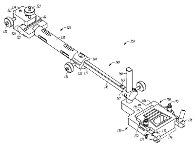
[00162] An ankle resection system 250 (see FIG. 21) can include an
anchor
assembly 120 as illustrated in FIG. 15. Although this device will be described
in
relation to an ankle joint surgery, the terms "proximal", "distal",
"anterior",
"posterior" etc. are used for explanatory purposes only and should not be
construed
as limiting. At the anchor proximal end 118, the anchor assembly 120 can
include
an anchor main block 121 which can be block shaped, cylindrically shaped, oval
shaped or otherwise and can house several apertures, openings and/or
adjustment
features and can include a tibia pin aperture 134 suited for pinning the
anchor main
block 121 to a tibia 12 (see FIG. 22). The anchor main block 121 can include a
mechanism for securing the anchor main block 121 to a pin passing through the
tibia
pin aperture 134, such as a threaded bolt 124 tightened or loosened by a knob
138
on an anchor adjustment member 126. The threaded bolt 124 can pass through a
threaded opening 139 and engage a surface of the pin passing through the tibia
pin
aperture 134 The tibia pin can be secured to the main block 121 in any
suitable
manner including using any type of holding, clamping or reversible locking
mechanism. At a main block distal end 86, the anchor main block 121 can
include a
shaft head mating recess 128, configured to receive a shaft head 125. The
shaft head
125 can be positioned on a shaft proximal end 87 of an anchor shaft member
130,
which extends to a distal end 119 of the anchor assembly 120. The shaft head
125
can be configured to be adjustable in two dimensions such as an angular
adjustment
31
CA 02872799 2014-11-06
WO 2013/169475
PCT/1JS2013/037758
88 and a medial lateral adjustment 89. The shaft head 125 can have a
cylindrical
shape which can allow it to be rotated within the shaft head mating recess 128
and
providing the angular adjustment 88. The cylindrical shape of the shaft head
125 can
also allow a medial/ lateral movement within the shaft head mating recess 128
and
thereby allowing both an angular adjustment 88 and a medial lateral adjustment
89
to the anchor shaft 130 which extends distally from the shaft head 125. The
mating
features of the shaft head 125 and the shaft head recess 128 can be reversed
such
that the anchor main block 121 can include a positive cylindrical member and
the
shaft head can include a recess to receive the positive cylindrical member.
[00163] The shaft head 125 can be locked into a position by a shaft head
adjustment member 123 which can include a threaded bolt 124 attached to a knob
138. The threaded bolt 124 can pass through a threaded opening 139 and engage
a
surface of the shaft head 125. The anchor block 121 can include a retaining
pin 129
configured to limit the medial/lateral movement of the shaft head 125 and keep
the
shaft head 125 from falling out of the anchor block 121 while the shaft head
125 is
not locked in a position. The anchor shaft 130 can include a lumen 127
configured
to receive an extension rod 140 (see FIG. 16) and allow longitudinal movement
of
the extension rod 140 within the length of the anchor shaft 130. The anchor
shaft
130 can include sight slots 141 or openings to view a position of a rod
proximal end
144 or any portion of the extension rod 140 (see FIGS. 16 and 21). The distal
end
119 of the anchor assembly 120 can include a distal end attachment member 132.
The distal end attachment member 132 can include a length adjustment member
131
configured to tighten or loosen a knob 138 attached to a threaded bolt 124
which
can pass through a threaded opening 139, engage the extension rod 140 and lock
or
unlock its position. The distal end attachment member 132 can include a distal
end
flat 135 which can ensure that the extension rod 140 cannot rotate within the
lumen
127 and can be assembled facing one direction. The distal end attachment
member
132 can include an anchor frame post aperture 133 which can be configured
substantially transverse to the direction of the lumen 127. In an alternative
embodiment, the anchor frame post aperture 133 can be configured to engage a
32
CA 02872799 2014-11-06
WO 2013/169475
PCT/1JS2013/037758
frame post 160 (see FIG. 21) and bypass any need for the extension rod 140
(see
FIG. 16).
[00164] FIG. 16 illustrates the extension rod 140 which can include a
longitudinal member 149 extending from the rod proximal end 144 to a rod
distal
end 145. The extension rod 140 can be shaped in cross section as round,
square,
oval or otherwise and can include at least one flat 143 (see FIG. 21) along at
least a
portion of its length, configured to mate with a distal end flat 135 of the
anchor shaft
130 (sec FIG. 15) and which can ensure that the extension rod 140 can be
positioned in the lumen 127 of the anchor assembly 120 in only one
orientation.
The rod distal end 145 can include a frame post aperture 147 configured to
receive a
frame post 160 (see FIG. 21). The frame post aperture 147 can include a
geometry
such as a frame post aperture flat 148 configured to mate with a frame post
flat 161
and limit the orientation of the connection between the extension rod 140 and
the
frame 150. The geometry of the mating features of the extension rod 140, such
as
flat 143 and distal end member 132, such as distal end flat 135, can include
any
type of polygon, key/keyway, star shape, positive/negative feature which can
limit
orientation to one direction (see FIGS. 15, and 21). Similar geometries can be
applied to the mating features of the anchor frame post aperture 133 or the
frame
post aperture 147 (see FIGS. 15, 16, and 17). A proximity adjustment member
146
can provide adjustment of the position of the rod distal end 145 relative to
the frame
post 160 (see FIG. 22) and can include a threaded bolt 124 and a knob 138. The
threaded bolt 124 can pass through a threaded opening 139, engage a surface of
the
frame post 160 and lock movement of the frame post 160 relative to the
proximity
adjustment member 146.
[00165] FIG. 17 illustrates a resection frame 150 which can include a
longitudinal body member 77 extending from a proximal end 78 to a distal end
79.
The resection frame 150 can include a frame post 160 extending in a
substantially
transverse direction from the longitudinal body member 77. The longitudinal
body
member 77 can include a proximal body portion 220. The proximal body portion
220 can be a central area from which extend a medial leg 153 and a lateral leg
157.
The longitudinal body member 77 can include an opening 155 bordered on each
33
CA 02872799 2014-11-06
WO 2013/169475
PCT/1JS2013/037758
side by the lateral leg 157 and the medial leg 156. The opening can be
configured to
receive a portion of a resection guide 170 (see FIG. 21). The longitudinal
body
member can include an anterior face 164 opposite a posterior face 81 (not
pictured).
The posterior face 81 can be configured to rest against a bone or joint such
as an
ankle joint 10 during a resectioning procedure (see FIG. 22). The longitudinal
body
member 77 can include one or more apertures near the proximal end 78 such as a
proximal tibial aperture 151 and a distal tibial aperture 152. These tibial
apertures
151, 152 can allow pins to pass through the apertures and into a bone such as
the
tibia 12 (see FIG. 22) at angles configured to provide security as well as
limiting
any conflict with resectioning cuts. The longitudinal body member 77 can
include
one or more apertures near the distal end 79 such as a medial talar aperture
153 and
a lateral talar aperture 154. These talar apertures 153 and 154 can allow pins
to pass
through the apertures and into a bone such as a talus 16 (see FIG. 22) at
angles
configured to provide security as well as limiting any conflict with
resectioning
cuts. The apertures 151, 152, 153, and 154 can include support members such as
a
lateral pin support 165 and a medial pin support 166 that can be configured to
provide additional support to the resection frame 150 as the apertures receive
pins
which can be connected to bones. The medial leg 156 and the lateral leg 157
can
include an attaching member 163 configured to provide attachment for the
resection
guide 170 (see FIG. 21). The attachment member 163 can include a threaded
hole, a
threaded stud, or a clamping mechanism. The distal end 79 can include a
posterior
recess 158 configured to allow clearance for a bone formation and can be a cut
out
shape oriented towards the posterior face 81.
[00166] A resection frame such as resection frame 150 can be shaped and
configured in a variety of manners to suit a particular anatomy and to work in
conjunction with a cutting guide such as guide 170, and in this regard, it
will be
understood that the various pieces or sections of a frame (e.g., arms, legs,
etc.),
whether the frame is modular or monolithic, can be provided in a variety of
shapes
and sizes and can be arranged in any suitable fashion so as to provide a
primary
opening in the frame such as opening 155 through which a bone cutting element
can
pass. In one example, the resection frame 150 can be configured for an ankle
joint
34
CA 02872799 2014-11-06
WO 2013/169475
PCT/1JS2013/037758
resection. In an example, a resection frame can be configured for a resection
of a
first metatarsophalangeal joint or an osteotomy of bones in the hand.
[00167] FIG. 18 illustrates a top view of the resection frame 150 which
can
include window recesses 162. The window recesses 162 can be oriented towards
the
opening 155 and can provide clearance for a bone formation and allow the
resection
frame 150 to be positioned in a more distal direction. A scribe line 159 can
be
engraved or marked across a medial leg 156 and a lateral leg 157 and can be
configured to aid the surgeon in placement of the resection frame 150 by
orienting
the scribe line 159 with a possible resection cut.
[00168] FIG. 19 illustrates a resection guide 170. The resection guide 170
can provide slots, openings or other interior or exterior surfaces which act
as
directional guides and supports for a bone cutting element 190 (see FIG. 22).
A
resection guide such as resection guide 170 and any associated bone cutting
element-guiding surfaces can be shaped and configured in any suitable manner
to fit
a particular anatomy and to work in conjunction with a resection frame such as
resection frame 150. The resection guide 170 can have its associated slots or
openings shaped to provide cuts for any form or location of resection. In one
example, the resection guide 170 can be configured for an ankle joint
resection. In
another example, the resection guide 170 can be configured for a resection of
a first
metatarsophalangeal joint or an osteotomy of bones in the hand. In an example
the
resection guide 170 could provide slots shaped to receive a bone saw or bone
knife.
In another example the resection guide 170 could have drill guides or a
combination
of saw guides and drill guides. The resection guide 170 can be rectangular,
round,
oval, or oblong and can have a guide proximal end 82 and a guide distal end
83. The
guide body 84 can be divided into an anterior body 177 and a posterior body
178.
The posterior body 178 can be shaped with a width 176 small enough to be
received
in the opening 155 of the resection frame 150 (see FIGS. 18 and 21). The
anterior
body 177 can be configured to be wide enough to engage the anterior face 164
of
the resection frame 150, such that the frame can provide support for the
resection
guide 170. The resection guide 150 can be configured without an anterior body
CA 02872799 2014-11-06
WO 2013/169475
PCT/1JS2013/037758
portion 178 and have the guide body 84 anterior to the anterior face 164 of
the
resection frame 150 (see FIGS. 18 and 21).
[00169] The guide distal end 83 can have a surface such as a distal
aspect 179
that can be shaped to act as a guide for a bone cutting element 190 (see FIG.
22).
The distal aspect can be planar to allow a bone cutting element 190 such as a
saw
blade or a knife blade to engage and be guided by the distal aspect 179 during
a
bone cutting procedure. The guide body 84 can include a series of transverse
cutting slots 172 which can allow the surgeon to select a size of a resected
bone void
182 (see FIG. 27) bordered on a distal end by the cut aided by the distal
aspect 179
and bordered on a proximal end by a cut aided by the selected transverse
cutting slot
172. The resection guide 170 can include a lateral cutting slot 169 and a
medial
cutting slot 171. The lateral cutting slot 169 and the medial cutting slot 171
can
connect cuts made using the distal aspect 179 and the transverse cutting slot
172. In
an example, the cutting slots 169 and 171 and a transverse cutting slot 172
can be
connected and need not be straight as shown. The resection guide 170 can
include a
cut out 173 which can aid the surgeon in viewing anatomical features the
resection
guide 170 is positioned over. The anterior body 177 can include
proximal/distal
adjustment slots 174 which can allow the resection guide 170 to be moved
relative
to the resection frame 150 (see FIG. 22). Bolts 175 can be used to lock any
movement between the resection guide 170 and the resection frame 150. FIG. 20
illustrates a top view of the resection guide 170. The lateral cutting slot
169 and the
medial cutting slot 171 can be angled inwardly towards the proximal end 82 to
provide resection cuts for an ankle resection system 250 (sec FIG. 21). The
resection guide can include slot markings 85 which can correlate to a selected
fusion
spacer or bone implant size. The resection guide 150 can be configured in
series of
sizes such as small, medium and large; to correlate to anatomical variations
in body
sizes.
[00170] FIG. 21 illustrates an assembled ankle resection system 250.
Depending on the size of a patient, either a longer or shorter extension rod
140 can
be selected. In some embodiments, no extension rod 140 is used. For example,
the
proximal tibial anchor 120 can couple directly to the resection frame 150. The
rod
36
CA 02872799 2014-11-06
WO 2013/169475
PCT/1JS2013/037758
proximal end 144 can be positioned in the lumen 127 of the anchor shaft 130 of
the
anchor assembly 120. The extension rod flat 143 and the distal end flat 135
can
ensure that the extension rod 140 is oriented correctly. The frame post
aperture 147
located at the rod distal end 145 of the extension rod 140 is slid over the
frame post
160 of the resection frame 150. The mating of the frame post aperture flat 148
(see
FIG. 16) and the frame post flat 161 (see FIG. 17) can ensure correct
orientation of
the resection frame 150. The resection guide 170 can be supplied in a wide
variety
of sizes and cutting slot configurations. A surgeon can select a resection
guide 170
and install it on the resection frame 150. The resection guide 170 can be
located on
the anterior face 164 of the resection frame 150 and can be attached or
coupled on
each side by bolts 175. The attachment or coupling of the resection guide 170
to the
resection frame 150 can be accomplished in any manner known to those skilled
in
the art to allow the resection guide 170 to be repositioned such that it does
not block
the opening 155. In an example, the attachment or coupling can be in the form
of a
hinge. In an example, the resection guide 170 can be pinned on one side of the
resection frame 150 and bolted on the other side. The width 176 of the
posterior
body 178 (see FIG. 19) of the resection guide 170 can be configured to fit in
between the medial leg 156 and the lateral leg 157 of the resection frame 150.
The
anterior body 177 of the resection guide 170 can be configured to be wider
than the
opening 155 of the resection frame 150 and the lower surface (not pictured) of
the
anterior body 177 can rest against the anterior face 164 of the resection
frame 150.
The posterior body 178 (see FIG. 19) can be very close to bones such as the
talus 16
and give support to cutting elements such as a saw blade 187 (see FIG. 22).
[00171] In FIG. 21,
the ankle resection system 250 can be positioned over the
tibia 12 and pinned to the tibia 12. Specifically, the main block 121 of the
anchor
assembly 120 can be positioned over the tubercle (not pictured) of the tibia
12.
Using the tibia pin aperture 134, a surgeon can pin the anchor assembly 120 to
a
proximal end (not pictured) of the tibia 12. When a desired axis position on
the
tubercle has been located, a fastener, such as a 125mm threaded fixation pin
can be
inserted through the tibia pin aperture 134 into the tibial tubercle. From
this
position, the ankle resection system 250 can be adjusted in several ways to
locate
37
CA 02872799 2014-11-06
WO 2013/169475
PCT/1JS2013/037758
the resection guide 170 at a correct position for resectioning. In some
examples a
fusion spacer 100 is used with an intramedullary nail 194 and the hollow
interior
116 of the fusion spacer 100 can be aligned with the intramedullary canal 195
(see
FIGS. 3C and 28) of a bone. In an example of an ankle resectioning, an axial
angle
of the ankle resection system 250 can be changed by rotating the system 1
about the
pin (not pictured) installed in the tibia pin aperture 134. Once an axis (not
pictured)
has been aligned with the tibia 12 (see FIG. 22), the axis adjustment member
126
can be tightened so that the anchor assembly 120 is immovable relative to a
pin (not
pictured) through the tibia pin aperture 134. The extension rod 140 can be
slidable
within the lumen 127 of the anchor shaft 124 and the position of the rod
distal end
145 can be adjusted in the longitudinal direction. A slope of the ankle
resection
system 250 can be adjusted to match a slope of a patient's tibia by rotating
the shaft
head 125 within the shaft head mating recess 128. The shaft head 125 can also
slide
in a medial lateral adjustment 89 direction to change the position of a
longitudinal
axis of the extension rod 140, the anchor shaft 130, the resection frame 150
and the
resection guide 170. Upon the location of a correct position, shaft head
adjustment
knob 123 can be tightened to restrict further movement of the shaft head 125.
There
are many ways that the adjustment of height, length, axial angle, vertical
angle and
medial/lateral movement of a resection frame 150 and a resection guide 170 can
be
accomplished and the examples presented here should not be construed as
limiting
the scope of the invention. In an example, the resection frame 150 is not
attached to
an anchor assembly 120 or an extension rod 140. In such an example, the
unattached
resection frame 150 is positioned and pinned to a joint or bone section.
[00172] FIG. 22 illustrates a resection frame 150 pinned to the tibia
12 and
the talus 16. Prior to installation of talus pins 188 and tibial pins 189, the
resection
guide 170 can be removed for better views of the ankle joint 10. The resection
frame
150 can include the scribe line 159 which can aid in the positioning of the
resection
frame 150. The scribe line 159 can be used to approximate a position of a most
distal resectioning cut. The distal cut can remove a portion of bone that
relates to
the type of fusion spacer that is being considered for use. In an example, a
spacer
such as the first fusion spacer 100 (see FIG. 3C) is contemplated and a 5mm
talus
38
CA 02872799 2014-11-06
WO 2013/169475
PCT/1JS2013/037758
cut can be used. In another example a spacer such as the second fusion spacer
200
(see FIG. 5C) is contemplated and a lOmm talus cut can be used. The scribe
line
159 can be positioned accordingly, using the length adjustment member 131 at
the
extension rod 140 to move the resection guide 170 proximally or distally (see
FIG.
21). Once such a position has been attained, the frame post 160 can be moved
in the
anterior/posterior direction to bring the resection frame 150 closer to the
bones of
the ankle joint 10. Putting the resection guide 170 close to the bones can
give bone
cutting elements 190 such as a saw blade 187 greater stability. The anterior/
posterior movement of the resection frame 170 can be locked by tightening the
proximity adjustment member 146. All of the previous adjustments can be used
to
properly align the ankle resection system 250 and also account for any bone
deformities which may be present.
[00173] Before pins
are placed in the resection frame 150, the foot 191 can be
placed at an advantageous angle, such as at 90 degrees to the tibia bone 12.
After
positioning of the foot 191 and the ankle resection system 250, the resection
frame
150 can be pinned to the ankle joint 10. The proximal aperture 151 and the
distal
aperture 152 can provide pathways for tibial pins 189. The apertures can
provide
angles for the pins which provide stability and also ensure that the pins do
not
interfere with any resection cuts. The resection frame 150 can be pinned to
the talus
16 by applying talus pins 188 through the lateral talar aperture 153 and the
medial
talar aperture 154 (see FIG. 17). The lateral pin support 165 and medial pin
support
166 (see FIG. 17) can be configured in any length or dimension needed to
provide
support for the pins 188. Both the tibial and talar pin apertures can be
angled in
manufacture to provide stability and holding strength. Any pin aperture can be
configured with a support member such as the lateral pin support 165. Any type
of
fastener, screw or pin, such as an 80mrn threaded fixation pin, can be used to
stabilize the resection frame 150. Pin apertures can be located at any
position or in
any number to secure the resection frame to a selected bone or joint.
Depending on
the type of incision made for the resection, some pins can be inserted
percutaneously. An auxiliary pin aperture 142 located on the extension rod 140
can
39
CA 02872799 2014-11-06
WO 2013/169475
PCT/1JS2013/037758
be utilized to pin the tibia 12 and provide more stability to the ankle
resection
system 250.
[00174] After pins have been placed, an additional adjustment of the
resection guide 170 can be made. The resection guide 170 can be moved in the
proximal/distal direction by loosening bolts 175 and allowing movement of the
resection guide via the proximal/distal adjustment slot 174. Once a desired
position
is found, the bolts 175 can be tightened to lock the resection guide 170 to
the
resection frame 150. In another example to allow proximal/distal movement of
the
resection guide 170, the slotted feature can be located in the resection frame
150. In
another example, the bolts 175 can be studs installed in the resection frame
150. The
distal aspect 179 of the resection guide 170 can be used as a cutting guide
for the
most distal cut of the procedure, in the present example, a resection of the
talus 16.
Before making any bone cuts, a surgeon can x-ray the placement of the assembly
as
in FIG. 23. Note how the angle of the bone cutting element 190, the proximal
end
of the talus 16, the distal end of the tibia 12, the tibial pins 189, the
talus pins188
and the location of the distal aspect 179 can be clearly seen in the
illustration of an
x-ray.
[00175] Returning to FIG. 22, a cutting device 192 such as a
reciprocating
saw can be used with a bone cutting element 190 to resect the proximal end of
the
talus 16. The bone cutting element 190 can be a saw blade 187, a knife, a
drill or
other device. The planar face of the distal aspect 179 can act as a guide for
the talus
resection. After the talus resection has been made, the surface of the talus
12 can be
inspected to ensure that a clean cut has been made and a good cortical rim
exists
which can support a fusion spacer. If necessary, the resection guide 170 can
be
repositioned to make a more distal cut by loosening the bolts 175 and
translating the
resection guide 170 distally, then re-locking the bolts 175. With the
resection guide
170 still locked in place a surgeon can determine the necessary height of a
tibial cut.
For a fusion spacer such as the first fusion spacer 100 (see FIG. 3C), this
can be a
7.5mm slot 193. When preparing for a fusion spacer such as the second fusion
spacer 200 (see FIG. 5C), a surgeon can choose to use a 25, 30, 35, or 40 mm
height device and will use the corresponding transverse cutting slot 172. In
another
CA 02872799 2014-11-06
WO 2013/169475
PCT/1JS2013/037758
example, the resection guide 170 can be configured with a configuration of
slots
sized and shaped to fit any application of joint or osteotomy resectioning. A
surgeon
can select the appropriate spacer height by feeling through the respective
transverse
slots 172 with a saw blade 187 or other instrument to determine where the
tibial
bone 12 begins.
[00176] FIG. 24 illustrates a tibial cut being performed using one of
the
transverse cutting slots 172. A surgeon can use a bone cutting element 190 to
cut the
tibia 12 through the most distal slot on the tibial bone where a flat surface
can be
achieved to support a fusion spacer or bone implant. The lateral cutting slot
169 and
the medial cutting slot 171 can be used to guide the bone cutting element 190
in
making lateral cuts to connect the transverse cut. Bone may not be present in
some
surgeries on the lateral sides. After the resection has been completed, the
resection
guide 170 can be repositioned away from the opening 155 (see FIG. 22) of the
resection frame 150 and the resection cuts can be examined to ensure that a
clean
surface exists to support a fusion spacer. Sharp inside corners can be
adjusted with a
rasp to remove any stress risers.
[00177] A surgeon can assess the fit of the resection surgery with the
resection frame 150 pinned in place and the resection guide 170 repositioned
so as
not to block the opening 155 (see FIG. 18). If additional cutting is needed
the
resection guide 170 can be replaced and adjusted if necessary for additional
cutting.
A small provisional spacer 195 such as illustrated in FIG. 25 can be used for
a
corresponding resection, or a large provisional spacer 196 such as illustrated
in FIG.
26 such as can be used after a replacement of a total ankle replacement
prosthesis as
described above. The provisional spacers 195 and 196 can have a provisional
slot
197 configured to provide space for a guide wire or Kirschner wire used in
conjunction with a surgical procedure. Such a guide wire 117 can be seen
running
down the center of an intramedullary nail 194 in FIG. 28. Returning to FIGS.
25
and 26, the provisional spacers 195 and 196 can have a radiographic pin 198
which
can aid in placement and location of the provisional spacer. FIG. 26
illustrates the
distal end of an insertion tool 199 holding a large provisional spacer 196.
The
insertion tool 199 can include arms 183 of sufficient length to allow the
surgeon to
41
CA 02872799 2014-11-06
WO 2013/169475
PCT/1JS2013/037758
securely grasp the provisional spacer 196 for insertion into the resected bone
void
182 (see FIG. 27). The arms 183 can include retaining members 184 which can
act
to orient the provisional spacer 196 and provide support for pushing the
provisional
spacer 196 forward. The distal end of the arms 183 can include a toothed grip
185
for increased stability. The arms 183 can be configured narrow enough while
holding the provisional spacer 196, to allow a surgeon to pass the spacer or
an
implant through the opening 155 while the resection frame 150 (see FIGS. 24
and
18) is fixed to the talus 16 and tibia 12. In practice, a distraction tool 181
as
illustrated in FIG. 27 can be used to spread the resected bone void 182 to a
desired
opening to insert a provisional spacer. Once the provisional spacer is in
position, a
surgeon can tamp the provisional with impaction tools until it is seated in
its desired
location. Using the distraction tool 181 and the insertion tool 199, the
surgeon can
then remove the provisional spacer 195 or 196. If the resection is acceptable,
the
surgeon can remove the resection frame 150. If more bone cutting is necessary,
the
surgeon can replace the resection guide 170 and adjust the location utilizing
the
proximal/distal adjustment slot 174 (see FIG. 24) or use a different sized or
configured resection guide 170.
[00178] FIG. 27 illustrates the insertion of a large fusion spacer 186
into the
resected bone void 182. The resection frame 150 (see FIGS. 24 and 18) can be
removed for this procedure. In another example the resection frame 150 is kept
in
place for the insertion of the fusion spacer. The distraction tool 181 can be
used to
spread the resected bones and provide an opening to insert the large fusion
spacer
186, which can be securely held by the insertion tool 199. The surgeon can
tamp
large fusion spacer 186 with impaction tools until it is seated in its desired
location.
[00179] FIG. 28 illustrates an x-ray of an ankle fusion 168. Fusion spacers
or bone implants can be used in conjunction with other fusion devices such as
intramedullary nails, bone plates and screws. Fusion spacers can have a hollow
interior 116 (see FIG. 3C) that can be sized to fit an intramedullary nail 195
such as
a 10 mm nail, or a nail of any other suitable size and shape to work with a
particular
surgery. In an ankle joint fusion 168, after positioning the large fusion
spacer 186, a
surgeon can insert an intramedullary nail 195 from the bottom of the foot,
through
42
the large fusion spacer 186 and into the intramedullary canal 167 of the tibia
12.
Bone plates can span a joint or an osteotomy procedure and can be attached to
the
bones as well as a fusion spacer. Bone screws can be placed through bones and
into
fusion spacers to provide stability.
[00180] The above Detailed Description includes references to the
accompanying drawings, which form a part of the Detailed Description. The
drawings show, by way of illustration, specific embodiments in which the
present
ankle resection systems and methods can be practiced. These embodiments are
also
referred to herein as "examples." Such examples can include elements in
addition
to those shown or described. However, the present inventors also contemplate
examples in which only those elements shown or described are provided.
[00181] The above Detailed Description is intended to be
illustrative, and not
restrictive. For example, the above-described examples shown or described (or
one
or more elements thereof) can be used in combination with each other. Other
embodiments can be used, such as by one of ordinary skill in the art upon
reviewing
the above description. Also, various features or elements can be grouped
together to
streamline the disclosure. This should not be interpreted as intending that an
unclaimed disclosed feature is essential to any claim. Rather, inventive
subject
matter can lie in less than all features of a particular disclosed embodiment.
Thus,
the following claims are hereby incorporated into the Detailed Description,
with
each claim standing on its own as a separate embodiment. The scope of the
invention should be determined with reference to the appended claims, along
with
the full scope of equivalents to which such claims are entitled.
[00182] While this invention has been described as having exemplary
designs, the present invention can be further modified within the scope of
this
disclosure. This application is therefore intended to cover any variations,
uses, or
adaptations of the invention using its general principles. Further, this
application is
intended to cover such departures from the present disclosure as come within
known
or customary practice in the art to which this invention pertains and which
fall within the limits of the appended claims.
43
CAN_DMS: \11041670111
CA 2872799 2018-02-01