Note: Descriptions are shown in the official language in which they were submitted.
CA 02873047 2014-11-07
WO 2013/169596
PCT/US2013/039523
-1 -
EMBOLIC PROTECTION SYSTEM
CROSS-REFERENCE TO RELATED APPLICATIONS
[0001]
This application is a PCT International Application of United
States Provisional Application No. 61/688,110, filed on May 8, 2012. The
disclosure of the above application is incorporated herein by reference in its
entirety.
FIELD
[0002]
The present teachings relate to a system for protecting aortic
arch vessels during cardiac procedures, endovascular cardiac and aortic
interventions, and non-operative treatment of infective endocarditis.
BACKGROUND
[0003]
The statements in this section merely provide background
information related to the present disclosure and may not constitute prior
art.
[0004] The current
rate of cerebrovascular stroke during aortic
valve replacement procedures using open, minimally invasive, or endovascular
approaches is known to be as high as 22%. Currently there are no FDA
approved devices for use in the United States designed to prevent
cerebrovascular stroke during heart valve replacement, and only two devices
are
available in Europe. However, the known devices have serious deficiencies. For
example, they are unreliable for creating a seal over the main vessel
junctions
within the aortic intima. This creates the opportunity for embolic particles
to
travel through the area of the compromised seal into the aortic arch arteries
potentially causing a cerebrovascular stroke. Additionally, such known devices
typically fail to provide a smooth transition between the devices and the
intimal
interface, which can result in stagnant blood flow at the interface and
increase
the risk for formation of stroke-causing emboli. Furthermore, such known
CA 02873047 2014-11-07
WO 2013/169596
PCT/US2013/039523
- 2 -
devices do not trap embolic vegetations associated with endocarditis, and
hence,
do not decrease the risk of neurological dysfunction.
SUMMARY
[0005]
The present disclosure provides an embolic protection
system for aortic arch vessels during a cardiac procedure and non-operative
treatment of endocarditis.
[0006] In
various embodiments, the present disclosure provides a
collapsible blood filtering aortic arch bridge comprising a dumbbell shaped
chassis structured to provide the bridge with a tubular waist, a first conical
end
formed and a second conical end such that only a periphery of the first and
second ends contact the intima of an aortic arch when the bridge is disposed
and
expanded within the aortic arch of a patient. The chassis is structured and
operable to bend to comply with the curvature of the aortic arch of the
patient.
The bridge additionally comprising a blood filtering sleeve disposed over an
interior or an exterior of the chassis and structured and operable to filter
blood
flowing through the bridge into aortic arch vessels of the patient when the
bridge
is disposed within the aortic arch. Furthermore the bridge comprises a
retrieval
sleeve disposed over the exterior of the chassis. The retrieval sleeve is
structured and operable to collapse the bridge to a cylindrical form for
retrieval of
the bridge from the aortic arch.
[0007] In
various other embodiments, the present disclosure
provides an embolic protection system comprising a collapsible blood filtering
aortic arch bridge and a bridge retrieval tool. The blood filtering bridge is
structured and operable to bend to comply with the curvature of an aortic arch
of
a patient into which the bridge is disposable. The bridge comprises a chassis
that is expandable and collapsible, wherein the chassis is structured to
provide
the bridge with a dumbbell-like shape when expanded, whereby the chassis has
CA 02873047 2014-11-07
WO 2013/169596
PCT/US2013/039523
- 3 -
a tubular waist, a first conical end formed at a first end of the waist, and a
second
conical end formed at an opposing second end of the waist such that only a
periphery of the first and second ends contact the intima of the aortic arch
when
the bridge is disposed and expanded within the aortic arch. The bridge
additionally comprises a blood filtering sleeve attached to the chassis. The
blood
filtering sleeve is structured and operable to filter blood flowing through
the
bridge into aortic arch vessels of the patient when the bridge is disposed and
expanded within the aortic arch. Furthermore, the bridge comprises a retrieval
sleeve disposed over an exterior of the chassis that is structured and
operable to
collapse the bridge to a cylindrical form for retrieval of the bridge from the
aortic
arch.
[0008]
The bridge retrieval tool is structured and operable to
retrieve the bridge from disposition within the aortic arch. In
various
implementations, the retrieval tool comprises a multi-layer catheter including
a
retention wire concentrically disposed within a movable outer sheath and a
bridge connector connected to a distal end of the retention wire. The bridge
connector is structured and operable to connect with the retrieval sleeve to
retrieve the bridge from disposition within the aortic arch. The tool
additionally
comprises a control handle connected to the catheter that is structured and
operable to control longitudinal movement of both the retention wire and the
outer sheath.
[0009]
Further areas of applicability of the present teachings will
become apparent from the description provided herein. It should be understood
that the description and specific examples are intended for purposes of
illustration only and are not intended to limit the scope of the present
teachings.
DRAWINGS
CA 02873047 2014-11-07
WO 2013/169596
PCT/US2013/039523
- 4 -
[0010]
The drawings described herein are for illustration purposes
only and are not intended to limit the scope of the present teachings in any
way.
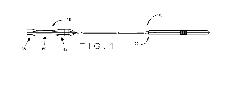
[0011]
Figure 1 is schematic of an embolic protection system, in
accordance with various embodiments of the present disclosure.
[0012] Figure 2 is
a schematic of a heart having a collapsible blood
filtering aortic arch bridge of the of embolic protection system shown in
Figure 1
disposed within the aortic arch, in accordance with various embodiments of the
present disclosure.
[0013]
Figure 3 is an isometric view of the collapsible blood filtering
aortic arch bridge of the embolic protection system shown in Figures 1 and 2,
the
bridge shown in an expanded state, in accordance with various embodiments of
the present disclosure.
[0014]
Figure 4 is an isometric view of the collapsible blood filtering
aortic arch bridge shown in Figure 3, the bridge shown in a collapsed state,
in
accordance with various embodiments of the present disclosure.
[0015]
Figure 5A is side view of a shape memory material chassis
of the collapsible blood filtering aortic arch bridge shown in Figures 3 and
4, the
chassis shown in the expanded and collapsed states, in accordance with various
embodiments of the present disclosure.
[0016] Figure 5B is
a side view of the shape memory material
chassis shown in Figures 5A having a blood filtering sleeve disposed over an
interior of the chassis, the chassis with the blood filtering sleeve shown in
the
expanded and collapsed states, in accordance with various embodiments of the
present disclosure.
[0017] Figure 5C is
side view of the shape memory material chassis
and blood filtering sleeve shown in Figures 5B having a retrieval sleeve
disposed
over an exterior of the chassis providing the aortic arch bridge shown in
Figures
CA 02873047 2014-11-07
WO 2013/169596
PCT/US2013/039523
-5-
3 and 4, the aortic arch bridge shown in the expanded and collapsed states, in
accordance with various embodiments of the present disclosure.
[0018]
Figure 6 is a cross-sectional view of the blood filtering aortic
arch bridge shown in Figure 3, in accordance with various embodiments of the
present disclosure.
[0019]
Figure 7 is an isometric view of a bridge retrieval tool of the
embolic protection system shown in Figure 1, in accordance with various
embodiments of the present disclosure.
[0020]
Figure 8 is a side view of a bridge coupling mechanism of
the bridge retrieval tool shown in Figure 7, in accordance with various
embodiments of the present disclosure.
[0021]
Figure 9 is a cross-sectional view of the bridge coupling
mechanism shown in Figure 8, in accordance with various embodiments of the
present disclosure.
[0022] Figure 10 is
a cross-sectional view of the bridge coupling
mechanism shown in Figures 8 and 9 having a magnetic button of the blood
filtering aortic arch bridge, shown in Figure 3, magnetically coupled to a
magnetic
bridge connector of the bridge coupling mechanism, in accordance with various
embodiments of the present disclosure.
[0023] Figure 11 is
a cross-sectional view of the bridge coupling
mechanism having the magnetic button magnetically coupled with the magnetic
bridge connector, as shown in Figure 10, and pulled into a locking claw of the
bridge coupling mechanism, in accordance with various embodiments of the
present disclosure.
[0024] Figure 12 is
a cross-sectional view of the magnetic button
magnetically coupled with the magnetic bridge connector and pulled into the
locking claw of the bridge coupling mechanism, as shown in Figure 11, having
an
CA 02873047 2014-11-07
WO 2013/169596
PCT/US2013/039523
- 6 -
outer sleeve of a multi-layer catheter of the bridge retrieval tool extended
over
the bridge coupling mechanism, in accordance with various embodiments of the
present disclosure.
[0025]
Figure 13 is a cross-sectional view of a portion of a control
handle of the bridge retrieval tool shown in Figure 7, in accordance with
various
embodiments of the present disclosure.
[0026]
Figure 14A is a side-view of the control handle shown in
Figure 13 having a thumb control pad of the control handle in a bridge
connection
position, in accordance with various embodiments of the present description.
[0027] Figure 14B
is a side-view of the control handle shown in
Figure 13 having the thumb control pad in a bridge securing position, in
accordance with various embodiments of the present description.
[0028]
Figure 14C is a side-view of the control handle shown in
Figure 13 having the thumb control pad in a bridge collapsing position, in
accordance with various embodiments of the present description.
[0029]
Figure 15 is a schematic of an aorta having the collapsible
blood filtering aortic arch bridge, shown in Figure 3, disposed and in an
expanded state therein, in accordance with various embodiments of the present
disclosure.
[0030] Figure 16 is
a schematic illustrating the collapsible blood
filtering aortic arch bridge disposed within the aorta and being progressively
collapsed as an outer sheath of the multi-layer catheter of the bridge
retrieval tool
is advanced over the collapsing bridge, in accordance with various embodiments
of the present disclosure.
[0031] Figure 17 is
a schematic illustrating the outer sheath of the
multi-layer catheter advanced over the entire collapsed blood filtering aortic
arch
bridge, in accordance with various embodiments of the present disclosure.
CA 02873047 2014-11-07
WO 2013/169596
PCT/US2013/039523
- 7 -
[0032]
Figure 18 is an isometric view of a bridge retrieval tool
shown in Figure 7, including an expandable outer sheath tip, in accordance
with
various embodiments of the present disclosure.
[0033]
Corresponding reference numerals indicate corresponding
parts throughout the several views of drawings.
DETAILED DESCRIPTION
[0034]
The following description is merely exemplary in nature and
is in no way intended to limit the present teachings, application, or uses.
Throughout this specification, like reference numerals will be used to refer
to like
elements.
[0035]
Referring to Figures 1 and 2, the present disclosure provides
an embolic protection system 10 that is structured and operable to prevent
embolic particles (emboli) 12 generated during aortic valve replacement from
traveling into the aortic arch arteries 14 potentially causing a
cerebrovascular
stroke. Generally, the system 10 includes a collapsible blood filtering aortic
arch
bridge 18 and a bridge retrieval tool 22. The bridge 18 is structured and
operable
to be disposed within the aortic arch 26 and span the juncture of the aortic
arch
arteries 14 with the aortic arch 26 such that substantially all the blood
flowing
from the heart 28 through the aorta 30 and into the aortic arch arteries 14
will
pass through, and be filtered by, the bridge 18, as described further below.
Importantly, the bridge 18 is further structured and operable to be very
flexible
such that the bridge will bend or contour to comply with the anatomy, e.g.,
curvature, of the aortic arch 26 and not distort the anatomy of the aortic
arch 26,
all the while being structured and operable to establish and maintain a tight
seal
between the aortic intima 34 and the ends 38 and 42 of the bridge 18 such that
emboli 12 cannot pass between the intima 34 and ends 38 and 42, but will be
forced to travel through the bridge 18 and thereby prevented from traveling
into
CA 02873047 2014-11-07
WO 2013/169596
PCT/US2013/039523
- 8 -
the arch arteries 14. Also, importantly, the bridge 18 is formed or structured
to
have a substantially dumbbell-like shape having a tubular waist 50 with a
first, or
upstream, conical end 38 formed at one end of the waist 50 and a second, or
downstream, conical end 42 formed at the opposing end of the waist such that
only a periphery of the upstream and downstream ends 38 and 42 contact the
intima 34 when the bridge 18 is disposed and expanded within the aortic arch
26.
[0036]
Referring now to Figures 3 through 6, as described in detail
below, the bridge 18 is structured and operable to have the dumbbell-like
shape
when in an expanded state, as illustrated in Figure 3, and is collapsible to a
hollow cylindrical form when in a collapsed state, as illustrated in Figure 4.
More
specifically, the bridge 18 comprises a chassis 46 (Figure 5A) that is
naturally
biased to the expanded state but easily transformable to the collapsed state,
an
elastic blood filtering sleeve 54 that covers and is attached to either an
interior or
exterior of the chassis 46 (Figure 5B), and an elastic retrieval sleeve 58
disposed
over the exterior of the chassis 46 (Figure 5C). In the embodiments wherein
the
blood filtering sleeve 54 is disposed over the exterior of the chassis 46, the
retrieval sleeve 58 is disposed over the exterior of the chassis 46 and the
blood
filtering sleeve 54.
[0037] As
described above, the chassis 46 is structured or formed
to have the dumbbell-like shape when in the expanded state. Therefore, it
should be understood that the chassis 46 provides and defines the waist 50,
the
upstream conical end 38 and the downstream conical end 42 of the bridge 18
when the bridge 18 is in the expanded state, and provides and defines the
hollow
cylindrical shape of the bridge 18 when the bridge 18 is in the collapsed
state.
[0038] In various
embodiments, the chassis 46 is fabricated of a
shape memory material, e.g., nitinol, to have the dumbbell-like shape, but is
collapsible to the cylindrical shape, as illustrated in Figure 5A. Hence, the
CA 02873047 2014-11-07
WO 2013/169596
PCT/US2013/039523
- 9 -
chassis 46 will naturally, i.e., without any external or environmental
influences,
assume the dumbbell-like shape, but can be easily compressed to have the
hollow cylindrical shape. For example, in various embodiments, the chassis 46
can be fabricated by laser-cutting and shape-setting a small tube of shape
memory alloy, e.g., nitinol, that forms a dumbbell shaped cage that can be
easily
compressed from the expanded state to the collapsed state, as exemplarily
illustrated in Figure 5A. Particularly, in various implementations, the
chassis 46
can be fabricated by laser-cutting small (e.g., 4mm) shape memory alloy (e.g.,
nitinol) tube and shape-setting the tube to acquire the expanded dumbbell
shape.
Radial sinusoidal rings can be formed at the conical ends 38 and 42, and
periodically within the smaller waist 50, (i.e., the mid-section) to provide
radial
stability. Additionally, longitudinal sinusoidal struts can be formed along
the
length of the chassis 46 to provide longitudinal stability/flexibility.
Furthermore,
the strut pattern of the chassis 46 is structured and operable to prevent the
outer
sheath 98 of the retrieval tool catheter 74 (described below with regard to
Figures
7-17) from binding with, snagging on, or catching on the bridge 18 during
retrieval, as described below.
[0039]
Additionally, in various embodiments, the chassis 46 is
structured or formed such that the conical upstream end 38 of the bridge 18
has
an outside diameter D that is greater than an outside diameter d of the
conical
downstream end 42 such that the bridge 18 conforms or accommodates the
anatomy of the aorta arch 26 (illustrated in Figure 6). That is, the
difference in
outside diameters D and d of the upstream and downstream ends 38 and 42 of
the bridge 18 are structure and operable to accommodate the change of the
inside diameter of the aorta 30 upstream of the aortic arch arteries (i.e.,
the
portion of the aorta 30 extending between the heart 28 and the arch arteries
14)
and the inside diameter of the aorta 30 downstream of the aortic arch arteries
14
CA 02873047 2014-11-07
WO 2013/169596
PCT/US2013/039523
- 10 -
(i.e., the portion of the aorta 30 extending between the arch arteries 14 and
the
abdomen). Thus, the upstream and downstream ends 38 and 42 are structured
or formed to have outside diameters D and d, respectively, designed to fit the
range of human aorta diameters without rupturing smaller aorta yet keeping the
bridge 18 in place within larger aorta. For example, in various embodiments,
the
outside diameter D of the upstream end 38 is 20% to 40% larger than the
outside
diameter d of the downstream end 42.
[0040]
Furthermore, the chassis 46 is structured or formed to
provide and define the waist 50 of the bridge 18 to have an outside diameter M
(shown in Figure 6) that is smaller than the end outside diameters D and d.
Therefore, importantly, when the bridge 18 is dispose within the aortic arch
26,
wherein the bridge 18 will bend to accommodate the contour of the aortic arch
26, the exterior of the waist 50 will not come into contact with the aortic
intima 34,
thereby preventing the development of micro clots along the length of the
waist
50. More particularly, the chassis 46 is structured or formed such that when
the
bridge 18 is disposed within the aortic arch 26, the waist 50 will generally
be
positioned or disposed in the mid-lumen or generally centered within the aorta
30. Therefore, blood will flow through the bridge 18 and pass through the
sides
of the waist 50 and the conical portion of the upstream end 38 into the arch
arteries 14 without the occurrence of blood stagnation between the intima 34
and
the bridge 18, thereby preventing the formation of micro-clots that could
hazardously enter the arch arteries 14. Still further, the chassis 46 is
structured
or formed to provide the waist 50 outside diameter M that is large enough to
provide an inside diameter of the waist 50 that is large enough to allow
catheters
and artificial aortic valves to pass through the bridge 18. Furthermore, the
reduced diameter waist acts as a barrier between instrumentation that
subsequently passes through the bridge 18 during medical/surgical procedures,
CA 02873047 2014-11-07
WO 2013/169596
PCT/US2013/039523
- 11 -
e.g., aortic valve replacement procedures, and the intima, reducing the
likelihood
that the bridge 18 or instrumentation will irritate or damage the intima 34.
[0041]
Additionally, as illustrated in Figure 3, the conical upstream
end 38 of the bridge 18 is structured to have a funnel portion 38A and a
substantially cylindrical end rim portion 38B extending from the funnel
portion
38A. Similarly, the conical downstream end 42 of the bridge 18 is structured
to
have a funnel portion 42A and a substantially cylindrical end rim portion 42B
extending from the funnel portion 42A. Importantly, the exterior portion of
the
end rim portions 38B and 42B are the only part of the bridge 18 that contact
the
aortic intima 34 when the bridge 18 is disposed in the aortic arch 26.
[0042]
Referring now to Figures 5B and 6, as described above, the
bridge 28 comprises the elastic blood filtering sleeve 54 that is attached to
and
covers either the interior or the exterior of the chassis 46. Although the
blood
filtering sleeve 54 can be disposed over and attached to the exterior of the
chassis 46 without departing from the scope of the present disclosure, for
clarity
and simplicity, the bridge 18 will be described herein as having the filtering
sleeve 54 disposed within and attached to the interior of the chassis 46.
[0043]
The blood filtering sleeve 54 is fabricated of a biocompatible
material, e.g., polyethylene terephthalate (PET), and is fabricated to allow
blood
flowing into and through the bridge 18 to pass through the blood filtering
sleeve
54, i.e., through the pores or openings of the sleeve 54, along the entire
length of
the bridge 18 between the upstream and downstream conical end rim portions
38B and 42B. Importantly, blood filtering sleeve 54 is fabricated such that
the
blood will flow through the blood filtering sleeve 54 into the aortic arch
vessels 14
without a reduction in blood pressure nor a reduction in flow volume, while
filtering the blood to prevent any emboli 12 from flowing into the arch
vessels 14.
CA 02873047 2014-11-07
WO 2013/169596
PCT/US2013/039523
- 12 -
[0044]
For example, in various embodiments, the blood filtering
sleeve 54 is fabricated of a knitted (as opposed to woven or braided)
biocompatible material, e.g., PET, to provide a knitted mesh. Utilizing a
knitted
material provides that the blood filtering sleeve 54 can expand and contract
generally only in the longitudinal direction (i.e., along a longitudinal axis
of the
bridge 18). Hence, expansion of the bridge 18 from the collapsed state to the
expanded state will not increase the porosity of the blood filtering sleeve
54.
That is, the knitted mesh blood filtering sleeve 54 will easily stretch only
in the
longitudinal direction such that when the bridge 18 is expanded to the
expanded
state, the size and area of the openings or pores of the knitted mesh will not
change. Rather, the openings or pores in the mesh will only elongate in a
longitudinal direction, i.e., along a longitudinal axis of the bridge 18, but
the size
of the openings or pores lateral direction, i.e., orthogonal to the
longitudinal axis
of the bridge 18, will not change. Therefore, the blood filtering sleeve 54
will
maintain its filtering capabilities and not allow larger size emboli 12 to
flow
through the blood filtering sleeve 54. In various embodiments, the blood
filtering
sleeve 54 is fabricated of knitted PET to have a porosity of between 50 to 300
microns, e.g., 100 micron, when the bridge 18 is deployed and in the expanded
state. Additionally, utilizing a knitted material allows the blood filtering
sleeve 54
to stretch as the chassis 46 bends during disposition within the aortic bridge
26.
Furthermore, in various implementations, the blood filter sleeve 54 will be
disposed within and attached to the chassis 46 such that the blood filter
sleeve
54 will be a relaxed state when the chassis 46/bridge 18 is in the expanded
state
and will be "bunched" within the chassis 46 with the chassis 46/bridge 18 is
in the
collapsed state.
[0045]
Additionally, the conical structure of the upstream end 38 is
designed such that the luminal blood flow, i.e., the blood flowing from the
heart,
CA 02873047 2014-11-07
WO 2013/169596
PCT/US2013/039523
- 13 -
into upstream end 38, will contact the blood filtering sleeve 54 covering
either the
interior or exterior of the funnel portion 38A. Moreover, the contact of the
blood
flow with the blood filtering sleeve 54 covering the funnel portion 38A of the
chassis 46 will apply a longitudinal force (i.e., a force parallel to the
direction of
the blood flow) to the funnel portion 38A. Subsequently, due to the conical
structure of the funnel portion 38A, the longitudinal force of the blood flow
against
blood filtering sleeve 54 will result in lateral, or radially outward, forces
exerted on
the funnel portion 38A, which will in turn exert a lateral, or radially
outward, force
on the cylindrical end rim portion 38B.
Importantly, this lateral, or radially
outward, force exerted on the end rim portion 38 by the blood flowing into the
bridge 18 will push, or press, the end rim portion 38 firmly against the
aortic
intima 34 such that the bridge 18 will be securely retained, or anchored,
within
the aortic arch 26, thereby preventing migration of the bridge 18 within the
aortic
arch 26, until the bridge 18 is removed using the retrieval tool 22, as
described
below. Furthermore, the conical ends 38 and 42 function to decrease the
parallelism between the direction of the luminal blood flow and the walls of
the
bridge 18. Therefore, the blood can flow through the blood filtering sleeve 54
anywhere between the upstream and downstream conical end rim portions 38B
and 42B, thereby significantly minimizing emboli causing stagnation along the
interior and/or exterior surface of the bridge 18.
[0046]
Referring now to Figures 5C and 6, as described above, the
bridge 18 comprises the retrieval sleeve 58 disposed over the exterior of the
chassis 46, or over the blood filtering sleeve 54 in the embodiments wherein
the
blood filtering sleeve 54 is disposed over the exterior of the chassis 46. The
retrieval sleeve 58 is attached (e.g. sutured) to the upstream end 38 of
chassis
46 such that the chassis 46 and blood filtering sleeve 54 are free to move or
slide
within the remainder of the retrieval sleeve 58. The retrieval sleeve 58 is
CA 02873047 2014-11-07
WO 2013/169596
PCT/US2013/039523
- 14 -
structured and operable to be connectable to the bridge retrieval tool 22 and
to
collapse the bridge 18 from the expanded state to the collapsed state such
that
the bridge 18 can be retrieved, or removed, when desired.
[0047]
The retrieval sleeve 58 is fabricated of a biocompatible
material and is fabricated to allow blood flowing through the blood filtering
sleeve
54, as described above, to flow into the aortic arch vessels 14 without a
reduction
in blood pressure nor a reduction in flow volume. For example, in various
embodiments, the retrieval sleeve 58 is fabricated to have a porosity of
between
200 to 500 microns when the bridge 18 is deployed and in the expanded state.
The retrieval sleeve 58 is fabricated of a braided (as opposed to knitted or
woven) biocompatible material to provide a braided mesh. For example, in
various implementations, the retrieval sleeve 58 comprises a braided strong
polymer monofilament such as polypropylene.
Utilizing a braided material
provides that a longitudinal force applied to the retrieval sleeve 58 will be
converted by the braided fabrication to a radially contracting force. Hence,
application of a longitudinal force to the retrieval sleeve 58 will radially
contract
the retrieval sleeve 58, and more importantly, radially contract the chassis
46 and
blood filtering sleeve 54 to transition the bridge 18 from the expanded state
to the
collapsed state.
[0048] The
retrieval sleeve 58 is secured to the chassis 46 at least
at the upstream end 38 and extends past, or overhangs, the downstream end 42
of the chassis 46. For example the retrieval sleeve 58 can overhang the
chassis
46 at the downstream end 42 of the bridge 18 by approximately 10-30 mm. In
various implementations, the retrieval sleeve 58 can additionally be heat-set
to
match the profile, or shape, of the chassis 46 when in the expanded state.
[0049]
The retrieval sleeve 58 includes a plurality of retrieval strings
62 that are connected to or integrally formed with the retrieval sleeve 58 at
their
CA 02873047 2014-11-07
WO 2013/169596
PCT/US2013/039523
- 15 -
distal, or upstream, ends and joined together at their proximal, or
downstream,
ends. For example, in various embodiments, the retrieval strings 62 are woven
into the braided mesh retrieval sleeve 58 at the upstream end 38 of the bridge
18.
The retrieval strings 62 are joined at the proximal, or downstream, ends
such that the retrieval strings 62 can be hooked, grasped, magnetically
attached
or otherwise connected to a bridge connector 66 (shown in Figure 8) of the
retrieval tool 22, as described further below. Once connected to the bridge
connector 66, the retrieval tool 22 will apply a longitudinal force to the
retrieval
sleeve 58, whereby the braided mesh of the retrieval sleeve 58 will convert
the
longitudinal force into a radial force that assists in collapsing the bridge
18 to the
cylindrical collapsed state such that the bridge 18 can be removed, or
retrieved,
from disposition within the aortic arch 26. In various embodiments, the
proximal,
or downstream, ends of the retrieval strings 62 are connected to, attached to,
or
joined together by, a magnetic button 70 that contains a small magnet 72,
e.g., a
small neodymium magnet disc (shown in Figure 10). As described below, in
such embodiments, the magnetic button 70 is magnetically connectable to the
bridge connector 66 of the retrieval tool 22 such that the bridge 18 is easily
connectable to the retrieval tool 22 for retrieval or removal of the bridge
when
desired.
[0050] Referring
now to Figure 7, as described above, the embolic
protection system 10 further includes the bridge retrieval tool 22. It should
be
understood that although the bridge retrieval tool 22 is exemplarily described
herein as part of the embolic protection system 10, and as being structured
and
operable to remove, or retrieve, the aortic arch bridge 18 from disposition
within
the aortic arch 26, the bridge retrieval tool 22 can be a stand-alone
retrieval tool
that is structured and operable to remove, or retrieve, other intra-luminal
devices,
or inter-tubular organ devices, e.g., other inter-arterial or inter-intestinal
stents or
CA 02873047 2014-11-07
WO 2013/169596
PCT/US2013/039523
- 16 -
devices, and remain within the scope of the present disclosure.
More
specifically, although the bridge retrieval tool 22 can be a stand-alone
retrieval
tool that is structured and operable to remove, or retrieve, other intra-
luminal
devices, or inter-tubular organ devices, e.g., other inter-arterial or inter-
intestinal
stents or devices, and remain within the scope of the present disclosure, for
simplicity and clarity the retrieval tool 22 will be exemplarily described and
illustrated herein as structured and operable to remove, or retrieve, the
aortic
arch bridge 18 described above.
[0051] In
various embodiments, the retrieval tool 22 includes a
multi-layer catheter, or tentacle, 74, a bridge coupling mechanism 78 disposed
at
a distal end of the multi-layer catheter 74, and a control handle 82 connected
to a
proximal end of the multi-layer catheter 74. The bridge coupling mechanism 78
is generally structured and operable to connect with the retrieval sleeve 58
of the
blood filtering aortic arch bridge 18, described above, to retrieve the bridge
18
from disposition within the aortic arch 26. And, the control handle 82 is
generally
structured and operable to control the operation of the bridge coupling
mechanism 78 and multi-layer catheter 74 to connect the bridge coupling
mechanism 78 to the bridge 18, collapse the bridge 18 and retrieve or remove
the bridge 18 from the aortic arch 26.
[0052] Referring
now to Figures 9 and 13, in various embodiments,
the multi-layer catheter 74 includes a flexible retention wire 86 slidably
concentrically disposed within a flexible core 90 that is concentrically
disposed
within a flexible fixed tube 94. The flexible core 90 is fabricated of any
flexible
material suitable for slidably housing the retention wire 86 and providing
support
for the fixed tube 94 such that the retention wire 86 and the fixed tube 94
can
flexibly bend but will not crimp or fold. The multi-layer catheter 74
additionally
includes a movable flexible outer sheath 98 that is slidably concentrically
CA 02873047 2014-11-07
WO 2013/169596
PCT/US2013/039523
- 17 -
disposed about the flexible fixed tube 94. The flexible core 90 is also
provides
support for the outer sheath 98 such that the outer sheath 98 can flexibly
bend
but will not crimp or fold.
[0053]
Referring now to Figures 8 through 12, the bridge coupling
mechanism 78 comprises the bridge connector 66, described above. The bridge
connector 66 is affixed to a distal end of the retention wire 86 such that the
bridge connector 66 extends from a distal end of the bridge coupling mechanism
78, which extends from a distal end of the catheter 74. As described above,
the
bridge connector 66 is structured and operable to hook, grasp, magnetically
attach to or otherwise connect to the retrieval strings 62. Hence, the bridge
connector 66 can be a hook, a clamp or clip, a magnetic, or any other device
or
mechanism suitable for securing the retrieval strings 62 of the bridge 18 to
distal
end of the retrieval tool catheter 74. Although the bridge connector 66 can be
a
hook, a clamp or clip, a magnetic, or any other device or mechanism suitable
for
securing the retrieval strings 62 of the bridge 18 to distal end of the
retrieval tool
catheter 74, the bridge connector 66 will be exemplarily described and
illustrated
herein a magnetic connector.
[0054] In
such embodiments, the bridge connector 66 comprises a
receptacle 102 and a magnet 106, e.g., a small neodymium magnet disc,
disposed in or near a bottom of the receptacle 102. Therefore, the magnetic
button 70 attached to the joined retrieval strings 62 of the aortic arch
bridge 18,
as exemplarily described above, is magnetically connectable to the bridge
connector 66 of the retrieval tool 22. Particularly, when aortic arch bridge
18 is
disposed within the aortic arch 26 and the retrieval tool catheter 74 is
inserted
into the aorta 30 such that the bridge connector 66 is in close proximity to
the
magnetic button 70, the magnetic button 70 is automatically magnetically drawn
into the receptacle 102 via the attractive forces between the button magnet 72
CA 02873047 2014-11-07
WO 2013/169596
PCT/US2013/039523
- 18 -
and the connector magnet 106, as shown in Figure 10. In
various
implementations, the shape of the button 70 and the shape of the receptacle
102
are complimentary such that the button 70 smoothly seats itself into the
receptacle 102 without binding. For example, the button 70 can have a curved
outer surface the seats smoothly into curved inner surface of the receptacle
102.
Additionally, in various implementations, small radiopaque markers can be
located at the contacting surfaces of the button 70 and the receptacle 102
that
are used to verify, via fluoroscopy, a successful connection of the button 70
with
the receptacle 102. Hence, the retrieval tool 22, particularly the catheter
74, is
readily, automatically, and easily connected to the aortic arch bridge 18,
particularly the retrieval strings 62 of the retrieval sleeve 58, when it is
desired to
remove, or retrieve, the bridge 18 from the aortic arch 26.
[0055] In
various embodiments, the bridge coupling mechanism 78
includes a locking claw 110 affixed to a distal end of the fixed tube 94. The
locking claw 110 is structured and operable to secure the connection of the
bridge connector 66 with the retrieval strings 62 of retrieval sleeve 58. The
locking claw 110 is formed to have a cylindrical shape wherein an outside
diameter of the locking claw 110 is smaller than in inside diameter of the
outer
sheath 98 such that the outer sheath 98 can be extended over the locking claw
110, as described further below. In various embodiments, the locking claw 110
comprises a plurality of fingers 110A that extend from a base 110B and have
wedge-shaped retaining teeth 110C formed at distal ends.
[0056]
The locking claw 110 is structured such that the fingers 110A
are biased to a normal position, wherein the locking claw 110 has the
cylindrical
shape, as shown in Figures 8 through 12. However, due to the wedge shape of
the retaining teeth 110C, the fingers 110A can temporarily spread apart by
pulling the bridge connector 66 into an interior chamber 126 of the locking
claw
CA 02873047 2014-11-07
WO 2013/169596
PCT/US2013/039523
- 19 -
110, whereafter the biasing of the fingers 110A will return the fingers 110A
to the
normal position. More specifically, once the bridge connector 66 has secured
the
retrieval strings 62 of the bridge 18, as described above, the retention wire
86 is
pulled in the X- direction, via operation of the control handle 82, as
described
below. This will consequently withdraw the bridge connector 66 and the
attached
retrieval strings 62 in the X- direction forcing the fingers 110A to spread
until the
bridge connector 66 and the attached retrieval strings 62 are disposed within
the
interior chamber 126, whereafter the fingers 110A will return to their normal
position. Once the bridge connector 66 and the attached retrieval strings 62
have been withdrawn into the interior chamber 126 and the fingers 110A have
returned to the normal position, the wedge shape of the retaining teeth 110C
will
prevent that bridge connector 66 and the attached retrieval strings 62 from
being
pulled back out of the interior chamber 126. Accordingly, the aortic arch
bridge
18 will be fixedly connected to the retrieval tool catheter 74.
[0057] For example,
in the embodiments wherein the aortic arch
bridge 18 includes the magnetic button 70 and the bridge connector 66 includes
the magnet 106, once the magnetic button 70 is magnetically connected to the
magnetic bridge connector 66 and seated within the receptacle 102, the
retention
wire 86 is pulled in the X- direction, via operation of the control handle 82.
This
will consequently pull the magnetically connected button 70 and bridge
connector
66 in the X- direction forcing the fingers 110A to spread. Continued pulling
of the
retention wire 86 in the X- direction will withdraw the magnetically connected
button 70 and bridge connector 66 into the interior chamber 126, as
illustrated in
Figures 11 and 12. Subsequently, the biased fingers 110A will return to their
normal position, whereby the wedge-shaped retaining teeth 110C will prevent
the
magnetically connected button 70, having the retrieval strings 62 of the
bridge
retrieval sleeve 58 attached thereto, from being pulled back out of the
interior
CA 02873047 2014-11-07
WO 2013/169596
PCT/US2013/039523
- 20 -
chamber 126. Accordingly, the aortic arch bridge 18 will be fixedly connected
to
the retrieval tool catheter 74.
[0058]
Once the bridge connector 66 and the attached retrieval
strings 62 have been pulled into the interior chamber 126 such that the aortic
arch bridge 18 is fixedly connected to the retrieval tool catheter 74, the
outer
sheath 98 can be advanced, via operation of the control handle 82, in the X+
direction over the locking claw 110, as shown in Figure 12. Furthermore, the
outer sheath 98 can be further advanced in the X+ direction over the aortic
arch
bridge 18, as described further below. Importantly, as the outer sheath 98 is
advanced in the X+ direction, due to the retention of the retrieval strings 62
by the
coupling mechanism 78, a longitudinal force will be applied by the outer
sheath
98 to the retrieval strings 62, and more importantly to the retrieval sleeve
58.
Consequently, as described above, the braided mesh of the retrieval sleeve 58
will convert the longitudinal force into a radial force that collapses the
bridge 18
to the cylindrical collapsed state such that outer sheath 98 can be advanced
over
the bridge 18, whereafter the bridge 18 can be removed, or retrieved, from
disposition within the aortic arch 26. It
is envisioned that in various
embodiments, to aid in the advancement of the outer sheath 98 over the bridge
18, the distal end of outer sheath 98 can include a plurality slits that allow
the
distal end to slight expand or widen as the outer sheath 98 contacts the
retrieval
strings and sleeve 62 and 58, thereby assisting in smooth advancement of the
outer sheath 98 over the bridge 18.
[0059]
Referring now to Figures 13 through 14C, the control handle
82 generally includes a housing 130 and catheter control module 134 slideably
disposed within the housing 130. The control module 134 is structured and
operable by an operator, e.g., a physician, surgeon or other medical
personnel,
to control movement of the retention wire 86 in the X- direction and the
CA 02873047 2014-11-07
WO 2013/169596
PCT/US2013/039523
- 21 -
movement of the outer sheath 98 in the X+ direction to connect the catheter 74
to
the aortic arch bridge 18 and collapse the bridge 18 for removal, as described
above. It should be noted that the control module 134 is further structured
and
operable by the operator to control movement of the retention wire 86 in the
X+
direction and the movement of the outer sheath 98 in the X- direction.
[0060] In
various embodiments, the control module 134 includes a
thumb controller 138, a retention wire fixture 142 and a core and fixed tube
fixture 146. The thumb controller 138 includes an outer sheath fixture 138A
that
is structured and operable to fixedly retain a proximal end of the outer
sheath 98
such that the outer sheath 98 will be advance and retracted in the X+ and X-
directions as the thumb controller 138 is moved in the X+ and X- directions.
The
thumb controller additionally includes a neck 138B extending from the outer
sheath fixture 138A through a J-shaped guide slot 150 in the housing 130. The
thumb controller 138 further includes a thumb pad 138C connected to a distal
end of the neck 138B such that the thumb pad 138C is disposed on the exterior
of the housing and is accessible to the operator holding the control handle
82.
The thumb controller 138 is slideably disposed within an interior cavity 154
of the
housing 130. Particularly, via manipulation of the thumb pad 138C by the
operator, the thumb controller 138 can be moved in the X+ direction and the X-
direction. More specifically, the operator can move the thumb pad 138C in the
X+
and X- directions causing the neck 138B to correspondingly slide within the J-
shaped guide slot 150 in the X+ and X- directions, which in turn causes the
outer
sheath fixture 138A, and importantly the outer sheath 98, to correspondingly
move in the X+ and X- directions. The J-shaped guide slot 150 is structured
and
operable to guide the movement of the thumb controller 138.
[0061]
The retention wire fixture 142 is slideably disposed within the
interior cavity 154 of the housing 130 and is structured and operable to
fixedly
CA 02873047 2014-11-07
WO 2013/169596
PCT/US2013/039523
- 22 -
retain a proximal end of the retention wire 86 such that the retention wire 86
will
be moved in the X+ and X- directions as the retention wire fixture 142 is
moved in
the X+ and X- directions, as described below. In various embodiments, the
retention wire fixture 142 includes a snap-lock tail 158 that is structured
and
operable to selectably retain, or lock, the retention wire 86 and the
retention wire
fixture 142 in a 'Withdrawn' position, wherein the bridge connector 66
connected
to the distal end of the retention wire 86 and retrieval strings 62 attached
to the
bridge connector 66 are withdrawn into the interior chamber 126 of the locking
claw 110, as described above. In various embodiments, the snap-lock tail 158
comprises a pair of opposing tines 158A that extend from a base 142A of the
retention wire fixture 142 and have wedge-shaped locking teeth 158B formed at
distal ends. As illustrated in Figure 13, when the thumb controller 138 and
the
retention wire fixture are in a 'Home' position, the locking teeth 158B
protrude
into, but do not extend through, a lock orifice 162 formed in a rear end of
the
housing 130.
[0062] As described
further below, to lock the retention wire and
fixture 86 and 142 in the Withdrawn position, the operator moves the thumb
controller 138 in the X- direction such that the outer sheath fixture 138A
pushes
the retention wire fixture 142 in the X- direction. As the retention wire
fixture 142
moves in the X- direction, the tines and locking teeth 158A and 158B of the
snap-
lock tail 158 are pushed through the lock orifice 162. Subsequently, the
locking
teeth 158B will extend out of the lock orifice 162, whereafter the resiliency
of the
tines 158A will push the locking teeth 158B radially outward such that the
wedge
shape of the locking teeth 158B engage the rear end of the housing 130, as
shown in Figures 14B and 14C, thereby locking the retention wire and fixture
86
and 142 in the Withdrawn position.
CA 02873047 2014-11-07
WO 2013/169596
PCT/US2013/039523
- 23 -
[0063] In
various embodiments, the control handle 82 includes a
biasing spring 166 disposed around the snap-lock tail 158 within the interior
cavity 154 of the housing 130 such that the biasing spring 166 will bias the
retention wire fixture 142 to the Home position. Moreover, the biasing spring
166
is structured and operable to maintain the retention wire fixture 142 in the
Home
position until the operator selectively moves the retention wire fixture 142
to the
Withdrawn position, as described above.
[0064]
The core and fixed tube fixture 146 is fixedly disposed within
the housing interior cavity 154 such that it is not movable in the X+ and X-
directions. Particularly, the core and fixed tube fixture 146 is structured
and
operable to fixedly retain the flexible fixed tube 94 and the flexible core 90
of the
multi-layer catheter 74 such that the flexible fixed tube and core 94 and 90
cannot move in the X+ and X- directions. Moreover, the core and fixed tube
fixture 146 is structured and operable to maintain the flexible fixed tube and
core
94 and 90 stationary as the outer sheath 98 and the retention wire 86 are
controllably moved over and within the fixed tube 94 and core 90 in the X+
and/or
X- directions, via operator manipulation of the thumb pad 138C as described
above.
[0065]
With further reference Figures 13 and 14A through 14C, the
J-shaped guide slot 150 comprises a short Home channel 150A that is connected
to a long sheath extension channel 150B via a switching channel 150C. Figure
14A illustrates the thumb pad 138C in the Home position wherein the neck 138B
is positioned within the Home channel 150A and is separated from the sheath
extension channel 150B by interstitial tab 170 formed in the housing 130
between the Home channel 150A and the sheath extension channel 150B.
Particularly, when the thumb pad 138C is in the Home position, the outer
sheath
CA 02873047 2014-11-07
WO 2013/169596
PCT/US2013/039523
- 24 -
fixture 138A is also in the Home position within the interior cavity 154 of
the
housing 130, as shown in Figure 13.
[0066]
Figure 14B shows the thumb pad 138C, and consequently,
the outer sheath fixture 138A moved from the Home position to the Withdrawn
position. As shown in Figure 13, when the thumb controller 138 is in the Home
position, the outer sheath fixture 138A is in contact with the retention wire
fixture
142. Hence, when the thumb controller 138 is moved from the Home position in
the X- direction, the neck 138B is moved along the Home channel 150A and the
retention wire fixture 142 is pushed by the outer sheath fixture 138A in the X-
direction, thereby moving the retention wire 86 in the X- direction. As
described
above, movement of the retention wire 86 in the X- direction withdraws the
connected retrieval strings 62 and bridge connector 66, e.g., the magnetically
connected magnetic bridge connector 66 and magnetic button 70, into the
interior
chamber 126 of the bridge coupling mechanism locking claw 110, as illustrated
in
Figure 11. Additionally, as movement of thumb controller 138 in the X-
direction
pushes the retention wire fixture 142 in the X- direction, the snap-lock tail
158 is
pushed through the lock orifice 162 in the rear end of the control handle
housing
130 until the retention wire fixture 142 and retention wire 86 are locked in
the
Withdrawn position, as illustrated in Figures 14B and 14C.
[0067] Once the
retention wire fixture 142 and retention wire 86
have been moved to the Withdrawn position, whereby the connected bridge
connector 66 and retrieval strings have been withdraw into, and secured
within,
the interior chamber 126 of the locking claw 110, the thumb pad 138C can be
moved in the Y+ direction to move the neck 138B of the thumb controller 138
from the Home channel 150A to the sheath extension channel 150B, via the
switching channel 150C. Subsequently, the thumb pad 138C can be pushed in
the X+ direction by the operator, thereby moving the outer sheath fixture 138A
in
CA 02873047 2014-11-07
WO 2013/169596
PCT/US2013/039523
- 25 -
the X+ direction and advancing the outer sheath 98 along the stationary fixed
tube 94 and core 90 in the X+ direction, as illustrated in Figure 12. As
described
above, movement of the outer sheath in the X+ direction with the retrieval
strings
62 securely retained by the bridge coupling mechanism 78 will exert a
longitudinal force on the braided bridge retrieval sleeve 58. As further
described
above, the braided mesh of the retrieval sleeve 58 will convert the
longitudinal
force to a radially contracting force such that the bridge 18 is progressively
collapsed from the expanded state to the collapsed state as the outer sheath
98
is advanced in the X+ direction such that the outer sheath 98 can be over the
collapsed bridge 18 until the entire bridge 18 is disposed and retained within
the
interior lumen of the outer sheath 98. Thereafter, the multi-layer catheter
74,
having the collapsed bridge 18 retained within the outer sheath 98, can be
withdrawn from the aorta 30, thereby removing, or retrieving, the bridge 18
from
the aortic arch 26.
[0068] Referring
now to Figure 18, in various embodiments, the
distal end of the outer sheath 98 can be structured and operable to expand and
contract, or open and close, to and from a sub conical shape to aid in the
retrieval of the bridge 18. For example, in various embodiments, the outer
sheath 98 can include an expandable mouth 100 formed, or disposed, at the
distal end. In such embodiments, the mouth 100 is structured and operable such
that when the outer sheath 98 is moved in the X+ direction to advance the
outer
sheath 98 over the collapsing bridge 18, as described above, the mouth 100
will
open, i.e., the distal end of the outer sheath 98 will expand, to aid in the
advancement of the outer sheath 98 over the collapsing bridge 18.
Additionally,
the mouth 100 is structured and operable to remain, or be maintained, in a
closed state, where the outside diameter of the mouth 100 is substantially the
same as the outside diameter of the remainder of the outer sheath 98, prior to
CA 02873047 2014-11-07
WO 2013/169596
PCT/US2013/039523
- 26 -
the outer sheath 98 being advanced over the bridge 18 and after the outer
sheath 98 has been advanced over the entire bridge 18. Hence, in such
embodiments, a larger insertion port incision in the patient will not be
needed to
accommodate the multi-layer catheter 74.
[0069] As described
above, the mouth 100 is structured and
operable to aid in the retrieval of the bridge 18. That is, it will
selectively
configure the distal end of the outer sheath 98 to more easily accommodate the
retrieval strings and sleeve 62 and 58 such that the outer sheath 98 can be
easily
advanced over the collapsing bridge 18 without catching or snagging on the
retrieval strings or sleeve 62 and 58.
[0070] In
various implementations, the mouth 100 can comprise a
plurality of radially equidistant longitudinal slits 104 cut down the distal
end, or tip,
of the outer sheath 98 that are structured and operable to allow the mouth 100
open and close as desired. In various implementations, the mouth 100 can
additionally comprise a thin elastomer, e.g., silicone, membrane or sleeve 108
disposed over the slits 104 to retain the mouth in the closed state prior to
advancement of the outer sheath 98 over the bridge 18 and return the mouth 100
to the closed state once the outer sheath 98 has been advanced entirely over
the
bridge 18. In various other implementations, to further aid in the ease of
advancing the outer sheath 98 over the bridge 18, the mouth 100 can further
comprise a flexible, smooth, and expandable woven mesh (not shown) that lines
the interior of the of the mouth 100, i.e., the interior of the distal end of
the outer
sheath 98 where the mouth 100 is disposed. Disposition of the mesh on the
interior of the mouth 100 will further reduce catching or snagging of the
outer
sheath 98 on the retrieval strings or sleeve 62 and 58 as the outer sheath 98
is
advanced over the bridge 18.
CA 02873047 2014-11-07
WO 2013/169596
PCT/US2013/039523
- 27 -
[0071] In
operation, to remove, or retrieve, the aortic arch bridge 18
from within the aortic arch 26, the multi-layer catheter 74 is inserted into
the aorta
30 via known procedures for inserting known catheters into the aorta, e.g.,
through an iliac artery via an incision near the patient's groin.
Subsequently, the
operator positions the multi-layer catheter 74 to connect the bridge connector
66
with the retrieval strings 62 of the bridge 18, as shown in Figure 15. For
example, in the embodiments wherein bridge connector 66 comprises the
magnet 106 and the retrieval strings 62 are joined together by the magnetic
button 70, the magnetic bridge connector 66 is placed in close proximity to
the
magnetic button 70, whereby the attractive magnetic forces between the
magnets 72 and 106 automatically connect the retrieval strings 62 of the
bridge
18 to the bridge connector coupling device 78.
[0072]
Next, the operator moves the thumb controller 138 from the
Home position to the Withdrawn position, via the thumb pad 138A, thereby
moving the retention wire fixture 142 in the X- direction. As described above
movement of the retention wire fixture 142 in in the X- direction, moves the
retention wire 86 within the flexible core 90 in the X- direction. This, in
turn,
withdraws the connected bridge connector 66 and retrieval strings 62, e.g.,
the
magnetically connected bridge connector 66 and magnetic button 70, into the
interior chamber 126 of the locking claw 110, whereby the retrieval strings 62
are
securely connected to the catheter 74. Once the retrieval strings 62 have been
secured within the locking claw 110, the operator moves the neck 138B of the
thumb controller 138 from the Home channel 150A, through the switching
channel 150C, into the extension channel 150B, via the thumb pad 138C. Next,
the operator slowly pushes the thumb pad 138 and outer sheath fixture 138A in
the X+ direction along the extension channel 150B, thereby slowly advancing
the
CA 02873047 2014-11-07
WO 2013/169596
PCT/US2013/039523
- 28 -
outer sheath 98 over the retrieving strings 62 and the portion of the
retrieval
sleeve 58 that overhangs the downstream end of the bridge chassis 46.
[0073] As
described above, advancement of the outer sheath 98
over the retrieving strings 62 and the overhanging portion of the retrieval
sleeve
58 causes the braided retrieval sleeve to exert radially collapsing forces on
the
chassis 46 and blood filtering sleeve 54. Consequently, the radially
collapsing
forces progressively collapse the bridge 18 to the collapsed state as the
outer
sheath 98 is advanced over the progressively collapsing bridge 18, as shown in
Figure 16. Finally, via further movement of the thumb pad 138C in the X+
direction along the extension channel 150B, the outer sheath 98 is advanced
over the entire collapsed bridge 18, as shown in Figure 17. Thereafter, the
multi-
layer catheter 74 and the collapsed bridge 18 retained within the outer sheath
98
of the catheter 74 are removed from the patient.
[0074]
Alternatively, to remove, or retrieve, other intra-luminal
devices from within the respective tubular organ, the multi-layer catheter 74
is
inserted into respective tubular organ via known procedures for inserting
known
catheters. Subsequently, the operator positions the multi-layer catheter 74 to
connect the bridge connector 66 with retrieval strings of the respective intra-
luminal device, whereafter the operator connects the bridge connector 66 with
the retrieval strings of the respective intra-luminal device.
[0075]
Next, the operator moves the thumb controller 138 from the
Home position to the Withdrawn position, via the thumb pad 138A, thereby
moving the retention wire fixture 142 in the X- direction. As described above
movement of the retention wire fixture 142 in in the X- direction, moves the
retention wire 86 within the flexible core 90 in the X- direction. This, in
turn,
withdraws the connected bridge connector 66 and retrieval strings into the
interior chamber 126 of the locking claw 110, whereby the retrieval strings
are
CA 02873047 2014-11-07
WO 2013/169596
PCT/US2013/039523
- 29 -
securely connected to the catheter 74. Once the retrieval strings have been
secured within the locking claw 110, the operator moves the neck 138B of the
thumb controller 138 from the Home channel 150A, through the switching
channel 150C, into the extension channel 150B, via the thumb pad 138C. Next,
the operator slowly pushes the thumb pad 138C and outer sheath fixture 138A in
the X+ direction along the extension channel 150B, thereby slowly advancing
the
outer sheath 98 over the retrieving strings and the respective intra-luminal
device
until the entire intra-luminal device is disposed within the outer sheath 98.
Thereafter, the multi-layer catheter 74 and the respective intra-luminal
device
retained within the outer sheath 98 are removed from the patient.
[0076] It
is envisioned that in various embodiments, the control
handle 82 can further comprise a retention wire withdrawal device (e.g., a
slider,
lever, wheel, etc.) structured and operable to continuously move the retention
wire 86 in the X- direction as the outer sheath 98 is advanced in the X+
direction.
Hence, in such embodiments, as the outer sheath 98 is being advance in the X+
direction by movement of the thumb pad 138C along the extension channel
150B, the retention wire withdrawal device simultaneously moves the retention
wire 86 in the X- at substantially the same rate of movement. Accordingly, in
such embodiments, the natural elongation of the bridge 18 as the bridge 18
collapses is compensated for by withdrawal of the retention wire 86, and more
importantly withdrawal of the bridge connector 66 and retrieval strings 62,
into
the outer sheath 98. That is, as the outer sheath 98 is advanced in the X+
direction over the bridge 18, the elongation of collapsing bridge 18 is
compensated for by withdrawing the downstream end 42 of the bridge in the X-
direction into the outer sheath 98 at the same rate as the outer sheath 98 is
advanced in the X+ direction. It is envisioned that the control handle 82 can
comprise and combination of gears, levers, pulleys, etc that are cooperatively
CA 02873047 2014-11-07
WO 2013/169596
PCT/US2013/039523
- 30 -
operable to ensure an optimum ratio between the advancement of the outer
sheath 98 in the X+ direction and the opposing withdrawal of bridge downstream
end 42 in the X- direction. Alternatively, it is envisioned that the
elongation of the
collapsing bridge 18 can be compensated for by the operator pulling the entire
control handle 82 and attached multi-layer catheter 74 in the X- direction as
the
outer sheath 98 is advanced in the X+ direction.
[0077]
The description herein is merely exemplary in nature and,
thus, variations that do not depart from the gist of that which is described
are
intended to be within the scope of the teachings. Such variations are not to
be
regarded as a departure from the spirit and scope of the teachings.