Note: Descriptions are shown in the official language in which they were submitted.
1
Description
Method for production of CO. H2 and methanol-synthesis gas from a synthesis
gas, in particular from acetylene off-gas
The invention relates to a method for production of a methanol-synthesis gas,
an
H2 product and a CO product from an H2- and CO-containing synthesis gas, in
particular an acetylene off-gas.
Methods for production of the abovementioned products from a synthesis gas are
known from the prior art. In this case, however, it proves to be a challenge
to
produce the three said products in greatly fluctuating amounts in the context
of a
method as economical as possible from a possibly highly contaminated, H2-and
CO-containing synthesis gas.
This problem is solved by a method described as follows.
Accordingly, in the method according to the invention, a synthesis gas stream
is
provided which is divided into a first and a second synthesis gas substream,
wherein only CO contained in the first synthesis gas substream is converted to
CO2 and H2 (watergas-shift reaction) using steam admixed to the first
synthesis
gas substream, wherein the first converted synthesis gas substream and a part
of
the second unconverted synthesis gas substream are respectively fed to two
separate scrubbing columns for scrubbing out CO2 with an amine-containing
scrubbing medium (e.g. MDEA), wherein, in particular, the scrubbing medium is
regenerated in a shared column, wherein the methanol-synthesis gas product
stream is mixed from one part of the scrubbed (converted) first synthesis gas
substream and/or the other part (where present) of the (non-converted) second
synthesis gas stream and also optionally two further streams (PSA residual gas
and crude H2 from a cold box, see below), in such a manner that a ratio of
(H2-0O2)/(CO+CO2) that is required for the methanol synthesis is established,
namely preferably in the range from 2.0 to 2.1, wherein, in addition, the
(scrubbed)
one part of the second synthesis gas substream is used for production of the
CO
product stream and the H2 product stream, and wherein the other part (where
CA 2873083 2019-09-23
CA 02873083 2014-11-10
P12C063-DEWO = IC0577 2
07.10.2014 ¨ Werner Fischer / Schulz
present) of the scrubbed (converted) first synthesis gas substream is used for
production of the H2 product stream.
Preferably, the synthesis gas stream (feed gas) is compressed in a first
process
step in order to be able to achieve, in particular, the desired product
pressures (H2
and methanol syngas) without further compression. In addition, the effective
gas
volume, and therewith the dimensions of the plant components used can be
reduced thereby. In addition, as a result, the steam used for the CO
conversion
need not be expanded excessively. In addition, a better absorption behaviour
is
achieved in the CO2 scrubber, and subsequent cryogenic gas separation
succeeds with a lower CO circulation rate, which reduces throughput and
consumption at the CO compressor (compression of the CO product stream and
of the CO circuit stream). Finally, owing to the compression provided at the
outset
of the feed in a pressure-swing adsorption (PSA), the H2 yield is increased,
and
the residual gas amount that is to be compressed is thereby reduced.
Particularly preferably, as synthesis gas stream (feed stream), use is made of
an
acetylene off-gas that has been scarcely utilized to date for further
production of
valuable material, which acetylene off-gas usually occurs in large amounts as
an
inexpensive by-product during acetylene production.
A typical specification of such an off-gas (AOG) in mol /0 appears as follows:
Constituent mol%
H2 59 to 64
CO 29 to 34
CO2 3.3 to 4.1
CH4 1.5 to 3.5
N2+Ar+He 0.3 to 1.0
02 0.1 tO 0.6
C2H6 0.001 to 0.1
C2H4 0.2 to 0.6
C3H4 0.003 to 0.03
Total S <0.1 mg/(S.T.P.)m3
NMP Traces
Temperature 15 C to 40 C
Pressure 9 bar to 12 bar
CA 02873083 2014-11-10
P12C063-DEWO = IC0577 3
07.10.2014 ¨ Werner Fischer / Schulz
The method according to the invention is distinguished, in particular, by the
possibility of effecting both the setting of the respectively required CO and
H2
product amounts and also ¨ in relation thereto ¨ the setting of the (H2-
0O2)/(CO+CO2) ratio in the methanol-synthesis gas product stream which, for
the
methanol synthesis (C0+2H2 CH3OH) is preferably in a range from 2.0 to 2.1.
The abovementioned setting can be performed, in particular, by appropriate
portioning of the synthesis gas stream into the two synthesis gas substreams,
and
also apportioning thereof to the methanol-synthesis gas product stream that is
to
be produced and the hydrogen- and/or CO product stream that is to be produced.
For this purpose, e.g., for setting the CO product amount, the second (non-
converted) synthesis gas substream can be fed to the said amine scrubber via a
first valve in such a manner that, in the case of appropriate setting of the
first
valve, a part of the second synthesis gas substream passes through the said
first
valve into the amine scrubber, and is available for production of the CO
product
stream and/or H2 product stream, and the other part is branched off upstream
of
the first valve and added to the methanol-synthesis gas product stream.
In addition, the converted (scrubbed) first synthesis gas substream, to set
the H2
product amount, can be added via a second valve to the pressure-swing
adsorption unit (PSA) (see below) wherein, in the case of an appropriate
position
of the second valve, one part of the scrubbed first (converted) synthesis gas
substream is branched off upstream of the second valve, and added to the
methanol-synthesis gas product stream, and wherein the other part of the
scrubbed first synthesis gas substream passes via the said second valve into
the
pressure-swing adsorption unit and is available for production of the H2
product
stream.
The (H2-0O2)/(CO+CO2) ratio being set in this case in the methanol-synthesis
gas
product stream is preferably measured (actual value), wherein the first
synthesis
gas substream is added via a third valve into the abovedescribed CO
conversion,
and the third valve is controlled in such a manner that the corresponding
conversion of CO and H20 to H2 and CO2 controls the said ratio to the
predefined
reference value in the range from 2.010 2.1. If, e.g., the H2 fraction is too
low, the
first synthesis gas substream is increased by corresponding adjustment of the
CA 02873083 2014-11-10
P12C063-DEWO = IC0577 4
07.10.2014 ¨ Werner Fischer / Schulz
third valve, in such a manner that per unit time more CO and H20 is converted
to
H2 and CO2. If the H2 fraction is too large, the first synthesis gas substream
is
decreased by appropriate adjustment of the third valve.
In summary, the conversion, in the case of a preset CO product amount (first
valve) is carried out in such a manner that, firstly, the desired H2 product
amount
(second valve) results, and secondly the said ratio in the mixed methanol-
synthesis gas product stream adopts a value in the range from 2.0 to 2.1 that
is
suitable for methanol synthesis.
In the event, that as feed, an acetylene off-gas stream is used, preferably,
unsaturated hydrocarbons present therein, before the portioning of the
synthesis
gas stream, are hydrogenated in a catalytic purification unit to give
saturated
hydrocarbons, wherein, in particular, C2H2 and/or C2H4 is hydrogenated to form
C2F16, or C3H4 and/or C3H6 is hydrogenated to form C3F18. In addition,
preferably
oxygen present in the acetylene off-gas stream is reacted with H2 and CO that
are
likewise present therein to form H20 and CO2. In addition, preferably, traces
of
sulphur and NMP (N-methylpyrrolidone) are retained from the acetylene off-gas
stream in the abovementioned catalytic purification unit.
Preferably, the said one part of the second synthesis gas substream which
serves, in particular, for production of the CO product or of the H2 product,
after
scrubbing out of CO2, is subjected to a temperature-swing adsorption in a
corresponding temperature-swing adsorption unit (adsorber station) for drying
(removal of water) and for removing residual CO2, wherein, preferably, at
least
one adsorber adsorbs, at low temperatures, H20 and CO2 present in the said
part
of the second synthesis gas substream, and then the at least one adsorber
loaded
with the components is regenerated at comparatively high temperatures by
purging with a crude hydrogen stream, wherein, as required, in particular in
the
partial-load case, a part of the part of the unconverted second synthesis gas
substream that is dried by the said temperature-swing adsorption and is freed
from CO2 is admixed to the crude hydrogen stream.
The part of the unconverted second synthesis gas substream that is dried and
freed from CO2 in this manner is thereafter cryogenically separated (partial
condensation or methane scrubbing) in a cold box at least into the CO product
CA 02873083 2014-11-10
P12C063-DEWO = IC0577 5
07.10.2014 ¨ Werner Fischer! Schulz
stream and a crude hydrogen stream, and also in particular a residual gas
stream,
wherein the CO product stream is compressed, and wherein at least one
compressed substream of the CO product stream is used for generating the cold
and/or heat (CO circuit streams) required for the said separation. For the
production of cold, in this case, in particular a CO substream is expanded in
a CO
expander. The residual gas stream formed in the separation is preferably
delivered at a battery limit and/or burnt.
In addition, the abovementioned crude hydrogen stream for the
regenerating/purging the at least one adsorber of the temperature-swing
adsorption unit is preferably split off from the crude hydrogen stream
produced in
the cold box and, after the regenerating/purging, is returned back to the
crude
hydrogen stream.
For generation of the H2 product stream, then, preferably, the crude hydrogen
stream and the other part of the scrubbed (converted) first synthesis gas
substream are mixed to form a hydrogen-rich PSA feed stream which is subjected
to a pressure-swing adsorption (PSA) for further purification. In this case,
the PSA
feed stream is passed under high pressure through at least one adsorber,
wherein
hydrogen present therein passes through the at least one adsorber and forms
the
H2 product stream. The heavier components such as, e.g., CO, present in the
PSA feed stream are adsorbed on the at least one adsorber. If the at least one
adsorber is fully loaded, the adsorbed components are desorbed at lower
pressure and the at least one adsorber is purged in particular with a purge
gas
formed from a substream of the H2 product stream produced. A residual gas
stream formed in this case containing the desorbed components and also the
purge gas is then compressed and can be fed as a further component to the
methanol-synthesis gas product stream.
As required, in particular with a predefinably small CO product stream and a
comparatively large H2 product stream, a part of the scrubbed part of the
unconverted second synthesis gas substream can be admixed to the PSA feed
stream. In addition, as required, in particular with a predefinably small H2
product
stream and a comparatively large CO product stream, a part of the crude
hydrogen stream can be added to the methanol-synthesis gas product stream.
= CA 02873083 2014-11-10
P12C063-DEWO = IC0577 6
07.10.2014 ¨ Werner Fischer / Schulz
In addition, the problem according to the invention is solved by a plant for
producing an H2 product stream, a CO product stream and a methanol-synthesis
gas product stream from an H2- and CO-containing synthesis gas stream (e.g.
acetylene off-gas).
The plant according to the invention preferably has a compressor which is
designed to compress (see above) the synthesis gas stream (feed stream),
wherein the compressor is preferably connected to a purification unit provided
downstream of the compressor, which purification unit is designed for the
catalytic
hydrogenation of unsaturated hydrocarbons present in the (compressed)
synthesis gas stream, and also for oxygen removal.
The said purification unit is preferably connected via a third valve to a
watergas-
shift reactor, in such a manner that a first synthesis gas substream is
feedable via
the third valve into the watergas-shift reactor which is designed for
converting CO
present in the first synthesis gas substream with H20 (steam) to H2 and CO2,
wherein any conversion unit (watergas-shift reactor) in addition is connected
to an
amine scrubber unit which in turn is connected via a second valve to a crude
hydrogen feed line for a pressure-swing absorption unit (PSA) and is also
connected to an outlet line for the methanol-synthesis gas product stream, in
such
a manner that the first synthesis gas substream is feedable from the watergas-
shift reactor into the amine scrubber unit and a part of the first synthesis
gas
substream is feedable into the crude hydrogen feed line of the PSA as a
constituent of the methanol-synthesis gas product stream that is to be
produced to
the said outlet line and ¨ according to setting of the second valve ¨ the
other part
of the first synthesis gas substream via the second valve.
In addition, the purification unit is preferably connected via a first valve
to the
amine scrubber unit, in such a manner that a part of the second synthesis gas
substream is feedable via the first valve into the amine scrubber unit,
wherein,
upstream of the first valve, the said outlet line branches off, in such a
manner that
¨ according to the setting of the first valve ¨ the other part of the second
synthesis
gas stream is feedable into any outlet line as a further constituent of the
methanol-
synthesis gas product stream.
CA 02873083 2014-11-10
P12C063-DEWO = IC0577 7
07.10.2014 ¨ Werner Fischer / Schulz
On the outlet line (Me0H syngas line) ¨ after admixture of all substreams ¨
preferably a sensor is provided for detecting the (H2-0O2)/(CO+CO2) ratio of
the
methanol-synthesis gas product stream mixed from the one part of the
(converted)
first synthesis gas substream, the other part of the (non-converted) second
synthesis gas substream, and also optionally of the PSA residual gas and a
part
of the crude hydrogen from the cold box, wherein, for controlling the third
valve, a
control unit is provided which is designed to control any ratio (actual value)
by
corresponding adjustment of the third valve to a preset reference value (set
value)
in the range from 2.0 to 2.1 (see above).
The amine scrubber unit is preferably designed for the separate scrubbing of
the
converted first synthesis gas substream and also of the one part of the
unconverted second synthesis gas substream, in order to remove or reduce CO2
present therein, wherein the amine scrubber unit preferably has a shared
column
for regenerating the respectively used CO2¨loaded scrubbing medium, which
shared column is designed for regenerating both scrubbing media. The amine
scrubber unit is, in addition, connected via a first line to a temperature-
swing
adsorption unit for drying the scrubbed one part of the unconverted second
synthesis gas substream and for removing CO2 still situated therein, wherein,
in
particular, the temperature-swing adsorption unit is designed to adsorb on at
least
one adsorber at low temperatures H20 and CO2 present in the said part of the
second synthesis gas substream and then to regenerate the at least one
adsorber
loaded with the said components by purging with a crude hydrogen stream at
comparatively high temperatures.
The temperature-swing adsorption unit is preferably connected via a second
line
to a cryogenic separation unit (cold box), in such a manner that the one part
of the
unconverted second synthesis gas substream that has been dried and freed from
CO2 is feedable via any second line into the cold box which is designed to
separate (see above) the part of the unconverted second synthesis gas
substream that has been dried and freed from CO2 into the CO product stream
that is to be produced, a crude hydrogen stream, and also, in particular, a
residual
gas stream. For compression of the CO product stream to the desired product
pressure, the cold box is connected to a CO compressor, which is additionally
.. designed to compress at least one CO substream for production of cold
and/or
heat to the desired CO circuit pressure (to approximately 30 bar to 40 bar)
and to
CA 02873083 2014-11-10
P12C063-DEWO = IC0577 8
07.10.2014 ¨ Werner Fischer / Schulz
recirculate it to the cold box. In addition, the plant for production of the
cold
required for the cryogenic separation is equipped, in particular, to expand at
least
one of the abovementioned CO substreams of the CO circuit stream in a CO
expander (to approximately 15 bar to 20 bar).
The cold box, in addition, is preferably connected via a regeneration/purge
gas
feed line to the temperature-swing adsorption unit which is designed for
feeding in
the crude hydrogen stream from the cold box which is used for the
regeneration/purge into the temperature-swing adsorption unit. In addition, a
first
bridging line (bypass) that is equipped with a valve is provided which
connects the
second line to the regeneration/purge gas feed line upstream of the
temperature-
swing adsorption unit, in such a manner that, as required, in particular in
the
partial-load case, a part of the part of the second (non-converted) synthesis
gas
substream that is dried and freed from CO2 by the said temperature-swing
adsorption can be admixed via the first bridging line to the crude hydrogen
stream
used for the regeneration/purge. In addition, a regeneration/purge gas return
line
is provided which connects the temperature-swing adsorption unit to the
hydrogen
feed line of the pressure-swing adsorption unit, in such a manner that loaded
regeneration/purge gas (crude hydrogen stream) can be fed into the crude
hydrogen feed line to the pressure-swing adsorption unit.
In addition, preferably, a second valve-equipped bridging line (bypass b) is
provided which connects the first line (between the amine scrubber unit and
the
temperature-swing adsorption unit) to the crude hydrogen feed line of the
pressure-swing adsorption unit, in such a manner that, as required, a part of
the
scrubbed part of the unconverted second synthesis gas substream is feedable
into the pressure-swing adsorption unit. In addition, a third valve-equipped
bridging line (bypass) is provided which connects the crude hydrogen feed line
of
the pressure-swing adsorption unit to the said outlet line for the Me0H
syngas, in
such a manner that, as required, a PSA feed stream (crude hydrogen from the
cold box, optionally converted and non-converted synthesis gas and also
regeneration/purge gas from the TSA) that is conducted in the crude hydrogen
feed line of the pressure-swing adsorption unit can be fed into the outlet
line and
thereby can be added to the methanol-synthesis gas product stream.
CA 02873083 2014-11-10
P12C063-DEWO = IC0577 9
07.10.2014 ¨Werner Fischer/Schulz
The pressure-swing adsorption unit is in detail preferably designed to deliver
the
(hydrogen-rich) PSA feed stream conducted in the crude hydrogen feed line at
high pressure via at least one adsorber, wherein hydrogen passes through the
at
least one adsorber and forms the said H2 product stream, and to adsorb on the
at
least one adsorber heavier components, in particular CO, present in this case
in
the PSA feed stream, wherein the pressure-swing adsorption unit is, in
addition,
designed to desorb at lower pressure the components that are adsorbed on at
least one adsorber and, in particular, to purge them with a purge gas formed
from
a substream of the H2 product stream generated. The pressure-swing adsorption
unit is connected, in particular, to a residual gas compressor which, in turn,
is
connected to the said outlet line, in such a manner that a residual gas stream
generated in the pressure-swing adsorption and containing the desorbed
components and also the purge gas can be compressed in the residual gas
compressor and then added to the methanol-synthesis gas stream.
Further details and advantages of the invention are to be illustrated by the
following figure description of an exemplary embodiment based on the figure.
In the drawing:
Fig. 1 shows a method according to the invention for producing an H2-,
CO- and methanol-synthesis gas product stream.
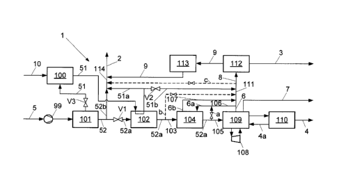
Figure 1 shows a schematic diagram of a method and of a plant 1 for the
production of an H2 product stream 3, a CO product stream 4 and also of a
methanol-synthesis gas product stream 2, which has a composition suitable for
methanol synthesis. As synthesis gas 5 used, preferably what is termed an
acetylene off-gas (ROG) 5 is used, which is a by-product of acetylene
production
which is available in comparatively large amounts.
The method according to the invention, however, is not restricted to AOG as
feedstock, but can also be applied to other synthesis gases 5 of similar
composition (especially similar H2/C0 ratio) with oxygen and/or unsaturated
hydrocarbons for production of the three described products 2, 3, 4. The
described process is also not restricted to the cited feed pressure according
to the
above table.
CA 02873083 2014-11-10
P12C063-DEWO = IC0577 10
07.10.2014 ¨ Werner Fischer / Schulz
In a first process step, the synthesis gas stream (acetylene off-gas stream or
AOG) 5 is first compressed 99 and then subjected in a purification unit 101 to
a
catalytic purification in which, in particular, in a 2-stage catalysis, the
unsaturated
hydrocarbons present in the synthesis gas stream 5 are hydrogenated (C2H2 and
C2H4 to C2H6, or C3I-14 and C3I-16 to C3I-18) and the oxygen present is
reacted with
H2 or CO to form H20 or CO2, respectively.
This prevents not only unsaturated hydrocarbons from freezing out in a
subsequent cryogenic separation (cold box 109), but also the accumulation of
explosive components such as 02 and acetylene (C2H2) in all subsequent plant
parts. In addition, preferably, traces of sulphur and NMP (N-
methylpyrrolidone) are
removed from the AOG 5.
After the above-described initial purification of the synthesis gas stream
(AOG) 5,
.. it is portioned into a first and a second synthesis gas substream 51, 52,
wherein
the first (still warm) synthesis gas substream 51, together with high-pressure
steam 10 is fed to a water-gas shift reactor 100 in order to produce, by
conversion
of CO+H20 to form CO2+H2 at a predetermined amount of CO product (first valve
V1) the required amount of H2 product (second valve V2) and in order to set
the
(H2-0O2)/(CO+CO2) ratio necessary for the methanol synthesis in the range
preferably 2.0 to 2.1 in the mixed methanol-synthesis gas product stream 2
(third
valve V3).
In this case, in detail, the second synthesis gas substream 52 is fed via the
first
valve Vito the CO2 scrubber unit (e.g. amine scrubber) 102, in such a manner
that at an appropriate position of the first valve V1, one part 52a of the
second
(non-converted) synthesis gas substream 52 is fed via the said first valve V1
into
the amine scrubber unit 102, wherein the other part 52b is added upstream of
the
first valve Vito an outlet line 114 for the methanol-synthesis gas product
stream
2.
The converted (scrubbed) first synthesis gas substream 51, to set the H2
product
amount, is added via a second valve V2 to a crude hydrogen feed line 111 of a
pressure-swing adsorption unit (PSA) 112, wherein, at an appropriate position
of
.. the second valve V2, one part 51a of the scrubbed first (converted)
synthesis gas
substream 51 is branched off upstream of the second valve V2 into the said
outlet
CA 02873083 2014-11-10
P12C063-DEWO = IC0577 11
07.10.2014 ¨ Werner Fischer / Schulz
line 114 and thereby added to the methanol-synthesis gas product stream 2, and
wherein the other part 51b of the scrubbed, converted first synthesis gas
substream 51 passes via the said second valve V2 into the crude hydrogen feed
line 111 to the pressure-swing adsorption unit 112. The (H2-0O2)/(CO+CO2)
ratio
being established in the outlet line 114 in the methanol-synthesis gas product
stream 2 is preferably continuously or repeatedly measured (actual value),
wherein the said third valve V3, via which the first synthesis gas substream
51 is
added into the watergas-shift reactor 100, is controlled in such a manner, via
the
conversion of CO and H20 to H2 and CO2 taking place in the watergas-shift
reactor 100, the said ratio approaches the predefined reference value in the
range
from 2.0 to 2.1.
In the amine scrubber unit 102, a combined CO2 removal is carried out (aMDEA
scrubbing), wherein both the converted first synthesis gas stream (AOG stream)
51 and the said one part 52a of the unshifted second synthesis gas stream 52
are
each fed to a scrubbing column for CO2 reduction. Whereas the CO2 in the
converted CO2-rich first synthesis gas stream 51 is preferably reduced to
about
3 mol% CO2 desired for the methanol synthesis, the CO2 of the said part 52a of
the unconverted second synthesis gas stream 52 is virtually completely removed
down to a few mol ppm. In addition to the two scrubbing columns connected to
one another energy efficiently on the scrubbing medium side, in particular, a
shared regeneration of the scrubbing media of the two scrubbing columns can be
carried out in only one regeneration column.
For the complete removal of the components water and CO2, the part 52a of the
unconverted second synthesis gas stream 52 is fed from the CO2 scrubber 102
via
a first feed line 103 into a temperature-swing adsorption unit (TSA) 104,
before it
passes via a second feed line 105 from the TSA 104 into a cryogenic gas
separator which is carried out in a cold box 109. This prevents both these
components from freezing out in the cold box 109 and also prevents any
blockages of plate heat exchanger passages, product reduction and also product
outage.
The loaded adsorber of the temperature-swing adsorption unit 104 is
regenerated
according to a defined step sequence (adsorber sequence) with a crude hydrogen
stream 6a from the said cold box 109 at higher temperatures, before said
CA 02873083 2014-11-10
P12C063-DEWO = IC0577 12
07.10.2014 ¨ Werner Fischer / Schulz
adsorber is again available for adsorption. As required, e.g. in the partial-
load
case, one part of the dried part 52a of the unconverted second synthesis gas
substream 52 which comes from the temperature-swing adsorption unit 104 is
admixed to the crude hydrogen stream 6a used for the regeneration/purging, in
order to provide the necessary regeneration gas amount, especially via a
bypass
or a first bridging line a which branches off from the second feed line 105.
For the synthesis gas stream (acetylene off-gas according to the table) 5 used
that is defined at the outset, preferably a methane scrubbing 109 is carried
out as
a cryogenic gas separation process. At a lower H2/C0 ratio and higher pressure
in
the synthesis gas stream (AOG) 5 used, however, a condensation process can
also be used. The synthesis gas 52a in both processes is fractionated by
rectification into the pure CO product stream 4, the crude hydrogen stream 6,
and
a residual gas stream 7.
/5
In detail, in the methane scrubbing 109, first the part 52a of the second (non-
converted) synthesis gas substream 52 (in particular in the form of a two-
phase
mixture) which is dried and freed from CO2 is impinged in a methane scrubbing
column with liquid methane, in such a manner that CO is scrubbed out of the
ascending gaseous H2-rich phase, wherein the crude hydrogen stream 6 is taken
off at the top of the methane scrubbing column, which crude hydrogen stream 6
is
passed (via the crude hydrogen feed line 111) into the pressure-swing
adsorption
plant 112. The condensate and the CO-loaded scrubbing methane, nitrogen, and
still-dissolved hydrogen are taken off from the sump of the methane scrubbing
column and passed to a second column, where H2 with small amounts of CO that
has been stripped off and also N2 are taken off overhead as residual gas
stream
7, and wherein the liquid phase occurring in the sump of the second column is
passed into a third column from which methane is obtained as sump product
which can be passed back into the methane scrubbing column and into the H2
stripping column, wherein excess methane can be added to the residual gas
stream 7. From the top of the third column, a fraction containing CO and N2 is
taken off, which fraction is added to a fourth column, from the top of which
substantially N2 which is added to the residual gas stream 7 is taken off and
from
the sump of which the CO product stream is taken off. Methane scrubbing
methods which are designed differently are of course equally conceivable.
CA 02873083 2014-11-10
P12C063-DEWO = IC0577 13
07.10.2014 ¨ Werner Fischer / Schulz
The CO thus produced is then compressed in a CO compressor 110 firstly to the
product pressure or product pressures, secondly to the required CO circuit
pressures. The CO circuit streams 4a are recirculated to the abovementioned
low
temperature process 109 and serve, e.g., as column heating, but they also
deliver
cold via expansion (Joule-Thomson effect) e.g. for overhead condensers. The
majority of the cold requirement is generated by a CO expander 108 which
expands a CO substream of the CO circuit stream 4a.
The crude hydrogen 6 generated in the cold box 109 is first mostly used as
regeneration/purge gas (crude hydrogen stream 6a via purge gas feed line 106)
in
the temperature-swing adsorption unit (TSA) 104 and is then passed (via the
regeneration/purge gas return line 107 and the crude hydrogen feed line 111)
to
the pressure-swing adsorption unit (PSA) 112 for fine purification.
The residual gas 7 from the cold box 109 is preferably delivered under low
/5 pressure at the battery limit and can, e.g., be underfired.
In order to produce the desired amount of hydrogen product, the crude hydrogen
stream 6 from the cold box 109 and the other part 51b of the converted first
synthesis gas stream 51 passed via the second valve V2 are passed to the PSA
112, where a high-purity H2 product stream (H2 > 99.9 mol%) is produced. As
required, also a part of the scrubbed part 52a of the unconverted second
synthesis gas substream 52 can also be fed to the PSA feed gas 8 (crude
hydrogen feed line 111) via a second bridging line (bypass) b (in particular
in the
event of low CO and high H2 amount of product) which bypass branches off from
the first feed line 103 downstream of the amine scrubber unit 102 and upstream
of
the temperature-swing adsorption unit 104 and opens out into the crude
hydrogen
feed line 111.
Conversely, in particular in the case of low amount of H2 product and high
amount
of CO product, a part of the crude hydrogen stream 6 from the cold box 109 can
be run via a third bridging line (bypass) c directly into the methanol-
synthesis gas
product stream 2 (discharge line 114).
Accordingly, there are a minimum of one and a maximum of three sources for the
H2 production, namely crude hydrogen 6 from the cold box 109, converted
CA 02873083 2014-11-10
P12C063-DEWO = IC0577 14
07.10.2014 ¨ Werner Fischer / Schulz
synthesis gas 51b (via the second valve V2) and also non-converted synthesis
gas 52a (via bypass b).
Since the residual gas 9 from the pressure-swing adsorption unit 112
principally
contains H2 and also CO, it is compressed in a residual gas compressor 113 to
the desired pressure and forms one of a maximum of four components of the
methanol-synthesis gas product stream 2. The further constituents are
unconverted 52b and converted synthesis gas 51a and optionally crude hydrogen
6 (via bypass c). With the aid of the conversion, for various predetermined
amounts of CO and H2 product, in each case the required (H2-0O2)/(CO+CO2)
ratio from 2.0 to 2.1 in the methanol-synthesis gas product stream 2 can be
set
(third valve V3).
The method according to the invention, as a result, permits, in particular,
the use
of a feedstock gas (AOG) which has scarcely been utilized to date for further
production of valuable material, is inexpensive and is available in large
amounts
as a by-product, for production of the high-quality grade products CO, H2 and
methanol syngas.
In this case, in particular via a suitable combination and control of the
process
groups (overall connection) both the amounts of CO and H2 product and also the
(1-12-0O2)/(C04-0O2) ratio necessary for the methanol synthesis from 2.0 to
2.1 can
be set. Thereby, maximum flexibility for the three products can be achieved,
in
dependence on the amount of AOG available, and maximum utilization of the
AOG for these products is achieved, while only a small residual gas stream 7
is
formed.
Finally, in particular, via a suitable interconnection of the process streams
in only
one CO2 scrubber unit 102, both the unconverted 52a and also the converted
AOG 51 can be treated, and the scrubbing medium can be regenerated in a single
column.
CA 02873083 2014-11-10
P12C063-DEWO = IC0577 15
07.10.2014 ¨ Werner Fischer / Schulz
List of reference signs
1 Plant
2 Methanol-synthesis gas product stream
3 H2 product stream
4 CO product stream
4a CO substream (circuit)
Feed (synthesis gas stream or AOG stream)
6 Crude hydrogen stream
6a, 6b Crude hydrogen stream (to/from TSA regeneration)
7 Residual gas stream from cold box
8 PSA feed stream
9 Residual gas stream (PSA)
51 First synthesis gas substream, converted
51a Part of the first synthesis gas substream
51b Other part of the synthesis gas substream
52 Second synthesis gas substream, unconverted
52a Part of the second synthesis gas substream (to/from CO2 scrubber)
52b Other part of the second synthesis gas substream (for the Me0H
Syngas)
99 Feed compressor
100 Water-gas shift reactor
101 Purification unit for purifying the feed gas (e.g. catalytic
hydrogenation)
102 CO2 scrubber (e.g. amine scrubber)
103 First feed line
104 Temperature-swing adsorption unit (TSA)
105 Second feed line
106 Regeneration/purge gas feed line
107 Regeneration/purge gas return line
108 CO expander
109 Methane scrubber unit (cold box)
110 CO compressor
111 Crude hydrogen feed line to PSA
112 Pressure-swing adsorption unit (PSA)
113 PSA residual gas compressor
CA 02873083 2014-11-10
=
P12C063-DEWO = IC0577 16
07.10.2014 ¨ Werner Fischer / Schulz
114 Outlet line for methanol-synthesis gas product
V1, V2, V3 Valves
a, b, c Bridging lines (bypasses)