Note: Descriptions are shown in the official language in which they were submitted.
CA 02873116 2014-09-11
WO 2013/138292 PCT/1JS2013/030419
ELECTRICAL ENERGY MANAGEMENT AND
MONITORING SYSTEM, AND METHOD
FIELD OF THE INVENTION
[0001] The present invention relates generally to electrical wiring and
distribution systems
and, more particularly, to systems for reducing unnecessary electrical energy
consumption.
BACKGROUND OF THE INVENTION
[0002] Many work areas and buildings are only occupied during a portion
of each day,
during which time the consumption of electricity or other forms of energy
(e.g. natural gas,
etc.) are typically at their highest. However, significant energy may still be
consumed during
periods of little or no use of the building or work area. For example, even
when computers,
monitors, radios, and similar devices are switched off, they still consume
power in "standby"
mode. Also, lights, space heaters, fans, and other devices that are left on
during periods of
non-use can consume significant amounts of energy, thus driving up utility
costs.
SUMMARY OF THE INVENTION
[0003] The present invention provides an electrical power management
system and method
that allows circuit-level control of power consumption in work areas or the
like, based on
occupancy detection and/or a predefined program that de-energizes individual
circuits
according to anticipated periods of non-use. This permits individual circuits,
or even
individual electrical outlets or power consumers, to be selectively de-powered
during periods
of actual or anticipated non-use of an area associated with those circuits, to
limit or prevent
unnecessary energy consumption by energy consumers (e.g., lights, appliances,
and the like)
on specific circuits.
[0004] According to one aspect of the invention, an electrical power
management system
includes a power control device in electrical communication with a multi-
circuit powered
infeed and a multi-circuit powered output. The power control device is
operable to
selectively control which circuits, of those that pass through the control
device, are energized
at a given time. The multi-circuit power infeed includes at least first and
second electrical
conductors on separate circuits, while the multi-circuit power output also
includes first and
second electrical conductors that are associated with the separate circuits of
the power infeed.
The power control device includes first and second electrical switches
associated with the
first and second conductors, an electronic communications module, and a
computer processor
in communication with the switches and the communications module. Each of the
switches
-1-
CA 02873116 2014-09-11
WO 2013/138292 PCT/US2013/030419
is operable, in response to the computer processor, between a closed
configuration and an
open configuration and to selectively connect and disconnect the conductors of
the power
infeed relative to the corresponding conductors of the power output. The
computer processor
is operable to open and close each of the electrical switches, independently
of one another, in
response to either or both of (i) an occupancy signal received via the
electronic
communications module, and (ii) a trigger or programmed event detected by the
computer
processor. An electrical power outlet is in electrical communication with one
of the electrical
conductors of the power output, and is configured to receive an electrical
plug of an electrical
consumer or device. The power control device can selectively provide
electricity to the
power outlet and the electrical consumer when the corresponding electrical
switch is closed.
[0005] Optionally, the power control device further includes a memory
module that is in
communication with the computer processor. The memory module can store a
program
and/or a trigger event. The computer processor is operable to open and close
the first and
second electrical switches in response to the trigger event or program stored
in the memory
module. For example, the trigger event may be a particular time of day and/or
date at which
one or more switches should be opened or closed according to the expected
occupancy or
non-occupancy of an area in which the device is operated.
[0006] Optionally, the signal received via the electronic communications
module of the
power control device is an occupancy signal indicative of whether a
corresponding area is
occupied by a person. The occupancy signal is generated by an occupancy
detector, such as a
motion sensor, heat detector, or the like, which transmits the occupancy
signal to the
electronic communications module of the power control device.
[0007] The electronic communications module may be in communication with
a computer
having a display, and the electronic communications module is configured to
receive program
instructions from the computer. The program instructions typically include one
or more
trigger events, such as the time of day, and day of the week, that each switch
should be closed
or opened to selectively energize or de-energize a given circuit.
[0008] According to another aspect of the invention, an electrical power
management system
includes a power infeed with at least first and second electrical infeed
conductors disposed in
a flexible armored infeed conduit, a multi-circuit power output, a power
control device, an
electrical junction box, and an electrical power outlet. The multi-circuit
power output
includes first and second electrical output conductors associated with
electrically separate
circuits and disposed in a flexible armored output conduit. The power control
device is in
electrical communication with the multi-circuit power infeed and the multi-
circuit power
-2-
CA 02873116 2014-09-11
WO 2013/138292 PCT/US2013/030419
output, the power control device including first and second electrical
switches associated with
the first and second electrical output conductors and operable between an open
configuration
and a closed configuration to permit selective electrical coupling of the
first and second
electrical output conductors to at least one of the first and second
electrical infeed conductors.
The electrical junction box is positioned along the flexible armored output
conduit of the
multi-circuit power output. The electrical power outlet is positionable at the
electrical
junction box and configured to receive an electrical plug of an electrical
consumer. The
electrical power outlet is in electrical communication with the first
electrical output conductor
when the electrical power outlet is coupled to the electrical junction box to
selectively
provide electricity to the power outlet and the electrical consumer when the
first electrical
switch is closed.
[0009] According to another aspect of the invention, an electrical power
management system
includes an electrical receptacle in electrical communication with at least
one circuit of a
multi-circuit power infeed having at least two electrical infeed conductors on
separate
circuits. The electrical receptacle includes a computer processor, a real-time
clock associated
with the computer processor, at least one hot electrical contact and at least
one neutral
electrical contact, an electrical relay, and electronic communications module.
The hot and
neutral electrical contacts are configured to receive respective contacts of
an electrical plug
associated with an electrical consumer. The electrical relay is operable to
selectively
energize the hot electrical contact in response to a signal received from the
computer
processor in response to at least one of (i) an occupancy signal received via
the electronic
communications module and (ii) a trigger event detected by the computer
processor. The
electronic communications module is in communication with a remote computer
having a
display, and is configured to receive program instructions from the remote
computer, where
the program instructions include one or more of the trigger events.
[ONO] According to another aspect of the invention, a method is provided
for controlling the
distribution of electrical power among a plurality of circuits in an
electrical system. The
method includes electrically coupling a multi-circuit power infeed to a power
control device,
the power control device including first and second electrical switches
associated with first
and second electrical conductors of the multi-circuit power infeed. The
electrical switches
are controlled by a computer processor of the power control device. A multi-
circuit power
output is electrically coupled to the power control device, wherein the multi-
circuit power
output includes first and second electrical conductors that are in selective
electrical
communication with the first and second electrical conductors of the multi-
circuit power
-3-
CA 02873116 2014-09-11
WO 2013/138292 PCT/1JS2013/030419
infeed according to the positions of the first and second electrical switches.
An electrical
power outlet is electrically coupled to one of the first and second electrical
conductors of the
multi-circuit power output. An occupancy signal is received via an electronic
communications module, or a trigger event is detected by the computer
processor. In
response to receiving an occupancy signal or detecting a trigger event, either
or both switches
are closed or opened to thereby electrically energize or de-energize the first
and second
electrical conductors of the multi-circuit power output.
[00111 Optionally, a power monitor is incorporated into the power control
device for
measuring and logging and/or transmitting power consumption data for each
circuit to
another computer, such as for historical power consumption data analysis.
[0012] Therefore, the present invention provides an electrical power
management system and
method that allows for individual control of electrical circuits in a work
area or the like, so
that one or more of the circuits that service the given area may be de-
energized during
periods of non-use. This permits conservation of energy, substantially without
affecting
productivity, while also allowing for power consumption data analysis for use
in optimizing
power consumption within a building or work area.
[0013] These and other objects, advantages, purposes, and features of the
present invention
will become apparent upon review of the following specification in conjunction
with the
drawings.
BRIEF DESCRIPTION OF THE DRAWINGS
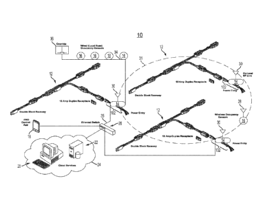
[0014] FIG. 1 is a diagram of a wired and wireless network-enabled
electrical power
management system in accordance with the present invention;
[0015] FIG. 2 is a diagram of a basic stand-alone electrical power
management system in
accordance with the present invention;
[0016] FIG. 3 is an enlarged perspective view of a portion of a multi-
circuit power
distribution assembly, including a power control device, shown partially
disposed in a
raceway of a work station divider or wall;
[0017] FIG. 4 is a wire diagram of a four-circuit version of the power
control device of FIG.
[0018] FIG. 5 is a wire diagram of the power output end portion
associated with the power
control device of FIG. 4;
[0019] FIG. 6 is a wire diagram of a pair of wired occupancy sensors that
are operable in
communication with the power control device via a local bus;
[0020] FIG. 7A is a wire diagram of a two-circuit version of the power
control device;
-4-
CA 02873116 2014-09-11
WO 2013/138292 PCT/US2013/030419
[0021] FIG. 7B is a wire diagram of a two-circuit power output associated
with the two-
circuit power control device of FIG. 7A;
[0022] FIG. 8A is a wire diagram of a three-circuit version of the power
control device;
[0023] FIG. 8B is a wire diagram of a three-circuit power output
associated with the three-
circuit power control device of FIG. 8A;
[0024] FIG. 9 is a wire diagram of another three-circuit power output
that can be associated
with a power control device;
[0025] FIG. 10 is a wire diagram of another four-circuit power output
that can be associated
with a power control device;
[0026] FIG. 11 is a wire diagram of another four-circuit power output
that can be associated
with a power control device;
[0027] FIGS. 12A-12F are perspective views of different exemplary wiring
arrangements
that are useful for electrically connecting a power control device to a new or
pre-existing
wiring arrangement;
[0028] FIG. 13 is a wire diagram of a receptacle-level power control
device in accordance
with the present invention;
[0029] FIG. 14 is a screen image of a computer display used for time-
based programming of
the power control device;
[0030] FIG. 15 is a screen image of a computer display showing historical
energy
consumption in a single circuit on an hourly basis;
[0031] FIG. 16 is a screen image of an occupancy display and control used
for selecting
which circuits will be energized when a given occupancy sensor detects that an
area is
occupied;
[0032] FIG. 17 is a screen image of a chart on a computer display,
depicting historical
detected occupancy of an area, as reported by an occupancy sensor to a power
control device;
[0033] FIG. 18 is a screen image of a chart on a computer display,
depicting historical day-
by-day of energy consumption in different circuits, as reported by a power
control device;
and
[0034] FIG. 19 is a screen image of a chart on a computer display,
depicting historical
minute-by-minute power consumption in an individual circuit, as reported by a
power control
device.
DESCRIPTION OF THE PREFERRED EMBODIMENTS
[0035] Referring now to the drawings of the illustrative embodiments
depicted therein, an
electrical power management system 10 (FIG. 1) allows a building or work area
-5-
CA 02873116 2014-09-11
WO 2013/138292 PCT/US2013/030419
administrator, or other authorized person, to set, control, and monitor
circuit-by-circuit power
consumption within the system. Power management system 10 includes a plurality
of multi-
circuit power distribution assemblies 12, each including a respective power
control device 14
in communication with a plurality of occupancy sensors 16, at least some of
which are on
different electrical circuits within a given assembly 12. Each power
distribution assembly 12
may service a different portion of a work area, for example, and is in
communication with
occupancy sensors 16 and/or with a local computer 18 (typically a computer
located at the
same premises as power distribution assembly 12), which communicates with each
power
control device 14, such as to program the device in a manner that will be
described in more
detail below.
[0036] Each power control device 14 is operable to selectively de-
energize one or more of
the circuits of its respective power distribution assembly 12 in response to
an occupancy
signal received from occupancy sensor 16, and/or in accordance with a power
control
program that is uploaded to the power control device 14 from local computer
18. This allows
for a selective de-energizing of particular circuits in a work area or the
like, to limit or
prevent unnecessary electrical consumption when a given area that is serviced
by a power
distribution assembly 12 is unoccupied, or when a given area is typically
unoccupied, or in a
period of limited use. Optionally, an occupancy signal received from occupancy
sensor 16
may override a programmed instruction to open a even circuit, so that
electrical power is
made available for persons in a work area at non-standard times, for example.
[0037] In the illustrated embodiment of FIG. 1, electrical power
management system 10
includes a remote computer 20 and/or a computer server 22. which may be
operated by a
third party service provider, an administrator, or the like. Remote computer
20 and server 22
can communicate with local computer 18 via Internet 24 or other computer
network. For
example, remote computer 20 and computer server 22 may communicate with local
computer
18 and/or power control device 14 via Internet 24 and an Ethernet switch 26
and/or other
network devices located on the premises of multi-circuit power distribution
assemblies 12.
[0038] It will be appreciated that substantially all electronic
communications within electrical
power management system 10 may be conducted wirelessly, or through wired
connections, or
through a combination of wired and wireless communications, without departing
from the
spirit and scope of the present invention. For example, some occupancy sensors
16 may
include wireless transmitters 28 for sending occupancy signals to a wireless
receiver or
communications module 30 located at power control device 14, thus forming a
wireless
network 31 (FIG. 1). Other occupancy sensors 16 may communicate with a wired
receiver or
-6-
CA 02873116 2014-09-11
WO 2013/138292 PCT/1JS2013/030419
communications module 32 of power control device 14 via dedicated wiring 34
(FIG. 1).
Other wiring 35 may be provided for communications between power control
device 14 and
Ethernet switch 26 or other communications hardware. It will be appreciated
that a given
power control device 14 may include a communications module that is capable of
both wired
and wireless electronic communications.
[0039] Optionally, a multi-circuit power distribution assembly 12 may be
operated in a
substantially autonomous manner in which the power control device 14
selectively energizes
and de-energizes individual circuits within power distribution assembly 12
according to
signals received from occupancy sensors 16 or the like, such as shown in FIG.
2. In this
arrangement, power control device 14 may not be programmable by an outside
device, such
as local computer 18, but would generally operate in response to occupancy
sensors only. In
addition, an override switch 36 (FIGS. 1 and 2) may be provided, which is in
communication
with wiring 34 (or in wireless communication with power control device 14), so
that one or
more circuits within power distribution assembly 12 may be energized
regardless of whether
the presence of a person is detected in the area of occupancy sensors 16.
[0040] Optionally, when power control device 14 is signaled to energize
one or more circuits
based on signals received from occupancy sensors 16 or override switch 36,
power control
device 14 may be configured to de-energize the circuit or circuits after a
predetermined
amount of time has passed since the switch was activated, or since the last
time an occupancy
signal was sent by an occupancy sensor 16. Optionally, a real-time clock 38
may be
associated with occupancy sensors 16 or override switch 36, so that activation
of the switch
or sensors can be set to "time out" after a predetermined amount of time, thus
sending a
signal to power control device 14 to de-energize its circuit or circuits.
Power control device
14 may also incorporate a real-time clock 38 for substantially the same
purpose, or for use in
running the power control device 14 according to a programmed schedule, as
will be
described below.
[0041] Power control device 14 is typically installed between a power
infeed 40 and one or
more junction blocks 42 having electrical power outlet receptacles 44
associated therewith
(FIG. 3). Power control device 14 is electrically coupled to power infeed 40
via a plurality of
bundled power infeed electrical conductors 46, and is further in electrical
communication
with junction blocks 42 via a plurality of bundled power output electrical
conductors 48.
Optionally, power infeed electrical conductors 46 are electrically coupled to
power infeed 40
via an infeed connector 50, while power output electrical conductors 48 are
electrically
coupled to junction blocks 42 or other downstream conductors via an output
connector 52. In
-7-
the illustrated embodiment, power infeed electrical conductors 46 and power
output
conductors 48 are shielded or protected by respective flexible metal or
armored conduits 53
(FIGS. 2 and 3). Junction blocks 42 define cavities 55 on their opposite sides
(FIG. 2) for
receiving power outlet receptacles 44. Junction blocks 42 are configured in a
manner that
allows a given receptacle 44 to electrically couple to one circuit when the
receptacle is in a
first orientation relative to junction block 42 when the receptacle is
received at cavity 55, and
that allows the receptacle 44 to electrically couple to a different circuit
when the receptacle is
in a second orientation (typically oriented 180 degrees to the first
orientation) relative to the
junction block 42. This is electrically illustrated in FIG. 5, for example, in
which different
junction blocks 42 are diagrammatically shown to permit electrical connections
(by different
circuits or outlet receptacles 44a-d) to different combinations of electrical
conductors 48 that
pass through each junction block 42. Such systems are readily available from
Byrne
Electrical Specialists, Inc. of Rockford, Michigan, and are described in more
detail in
commonly-owned U.S. Patent Nos. 5,259,787; 6,036,516; and 7,534,122.
100421 In the illustrated embodiment of FIG. 3, power control device
14, junction block 42
and power outlet receptacle 44, bundled electrical conductors 46 and 48, and
connectors 50
and 52 cooperate to form a portion of a given multi-circuit power distribution
assembly 12
(also shown in FIGS. 1 and 2), which is configured to be at least partially
disposed in a
raceway 54 defined in a wall or divider 56 or the like (FIG. 3). Although
raceway 54 is
shown at a lower end portion of a furniture divider or partition 56 in FIG. 3,
it will be
appreciated that raceway 54 may be disposed at substantially any position
along the divider
or wall 56, to provide power along substantially any divider or wall location.
For example,
the BYRNE 8-TRAC or BYRNE 4-TRAC electrical distribution assemblies,
available
from Byrne Electrical Specialists, Inc. of Rockford, Michigan, are configured
for such
= applications, and these may incorporate power control 'device 14 to serve
as suitable multi-
circuit power distribution assemblies 12. The above-referenced BYRNE 8-TRAC
and
BYRNE 4-TRAC systems are described in commonly-Owned U.S. Pat. No. 7,410,379
and
in commonly-owned U.S. patent application, Publication No. 2012/0064747,
respectively.
Optionally, a multi-circuit power distribution assembly may be positioned in a
raised floor, or
in raceways provided above a ceiling, without departing from the spirit and
scope of the
present invention.
100431 Power control device 14 includes an electronic communications
module 58 which, in
the illustrated embodiment of FIG. 4, includes a wired receiver or "local bus"
32, an Ethernet
-8-
CA 2873116 2018-02-09
CA 02873116 2014-09-11
WO 2013/138292 PCT/US2013/030419
transceiver 60, and wireless transceiver 30 for performing electronics
communications to
and/or from power control device 14. Wired receiver 32 includes a standard
RJ45 connector
62 or the like, for coupling to wiring 34 of occupancy sensors 16 and/or
override switch 36.
Ethernet transceiver 60 may similarly include a 10/100 Ethernet port (RJ45
connector) 64 or
the like, for wired communications with Ethernet switch 26 via wiring 35.
Wireless receiver
30 includes a transceiver antenna 66 to facilitate wireless communications
between power
control device 14 and wireless occupancy sensors 16, local computer 18, remote
computer 20
and server 22, or the like. For example, wireless receiver 30 may be a
transceiver operating
under 2.4 GHz ZIGBEE protocol, BLUETOOTH protocol, or substantially any
other
wireless communications protocol.
[0044] In the illustrated embodiment of FIG. 4, electronic communications
module 58
includes wired receiver 32, wireless receiver 30, and Ethernet transceiver 60,
all of which are
in electronic communication with a computer processor 68 in power control
device 14.
However, it will be appreciated that, depending on the need for a particular
application, one
or two of wireless receiver 30, wired receiver 32, and Ethernet transceiver 60
may be omitted,
thus providing reduced communications capability, but still providing limited
functionality.
For example, in the illustrated embodiment of FIG. 2, power control device 14
may include
only wired receiver 32 for communication with occupancy sensors 16 and
override switch 36,
in which case the power control device may lack the ability to communicate
with another
computer, for example.
[0045] Control device 14 further includes a plurality of electrical
switches 70, such as
electrical relays or the like, each of which corresponds to a respective "hot"
conductor among
the power infeed electrical conductors 46 (FIG. 4). For example, in the
illustrative
embodiment of FIG. 4, there are four electrically hot conductors (L1-L4), each
part of a
distinct electrical circuit that enters power control device 14 from power
infeed conductors
46. Each electrically hot conductor L1-L4 feeds into a respective one of
electrical switches
70, which are independently operable between an open configuration (as shown
in FIG. 4)
and a closed configuration in response to a signal received from computer
processor 68. In
addition to the electrically hot conductors L1-L4, power infeed electrical
conductors 46
include two neutral conductors Ni, N2 and two ground conductors G, IG that
pass unbroken
through power control device 14 and continue through to power output
electrical conductors
48.
[0046] A power supply 72 is electrically coupled to hot conductor Li and
neutral conductor
Ni in power control device 14, regardless of whether any of switches 70 are
open, such as
-9-
CA 02873116 2014-09-11
WO 2013/138292 PCT/US2013/030419
shown in FIG. 4. Power supply 72 draws power from power infeed 40 and supplies
the
electrical power needs of power control device 14. Power supply 72 may include
a battery
and/or an AC/DC power inverter. A memory module 74 is in communication with
computer
processor 68, and allows the processor to store triggered events such as a
time-based program
schedule defining times at which the circuits associated with hot conductors
L1-L4 will be
de-energized or re-energized by changing the position of the individual
electrical switches 70.
A real-time clock 38 may be incorporated into power control device 14 for use
in operating
time-based functions. Optionally, a power monitor module 76 is in
communication with
computer processor 68, and is individually electrically coupled using
inductive couplers 78 at
each of the electrically hot conductors Li-L4 of the power output electrical
conductors 48
using known techniques, to individually monitor, track, and report real time
power
consumption and/or historical power consumption data for the individual
circuits associated
with hot conductors Ll -L4.
[0047] Referring now to FIG. 5, the four hot conductors L1-L4 of power
output conductors
48 are (or are configured to be) electrically coupled to electrical consumers
via electrical
connections represented by power outlet receptacles 44a-d, which are also
identified as
"Circuit 1", "Circuit 2", "Circuit 3", and "Circuit 4" in FIG. 5. Each of
power outlet
receptacles 44a-d represents at least one power outlet receptacle for a
potential power
consumer (appliance, computer, lighting, power outlet, or the like), or
represents a potential
power consumer itself, which may draw power from one of the circuits passing
through
power control device 14. For example, first power outlet receptacle 44a may
represent a
plurality of power outlet receptacles at the floor level of a work area, which
are primarily for
powering computers, computer monitors, and peripheral devices; while second
power outlet
receptacle 44b may represent a plurality of power outlet receptacles at a work
surface level of
the work area, which may be primarily intended for powering chargers, fans,
pencil
sharpeners, radios, etc.; while third power outlet receptacle 44c may
represent area lighting
provided at individual workstations; and fourth power outlet receptacle 44d
may represent an
unused circuit that is available for later use, if desired.
[0048] Optionally, and by further example, each of power outlet
receptacles 44a-d may
represent a separate electrical circuit that provides power to a respective
one of four
individual workstations, so that each workstation (including computers,
monitors, area
lighting, peripheral devices, etc.) is powered by a respective one of Circuits
1-4. In this latter
example, it may be beneficial to de-energize one individual circuit for a
prolonged period,
such as during a planned vacation by the person assigned to a corresponding
work station. for
-10-
CA 02873116 2014-09-11
WO 2013/138292 PCT/1JS2013/030419
example, in addition to regular programmed (or occupancy-based) de-energizing
of the
circuit.
[0049] In the illustrated embodiment of FIG. 5, each of Circuits 1-3
(represented by power
outlet receptacles 44a-c) has one neutral conductor socket 80 that is
electrically coupled to a
first neutral conductor Ni of power output conductors 48, one ground conductor
socket 82
that is electrically coupled to a first ground conductor G1 of power output
conductors 48, and
one hot conductor socket 84a-c that is electrically coupled to a respective
one of hot
conductors LI-L3 of power output conductors 48. In this way, each of the
electrically
isolated hot conductors L1-L3 supplies current to a respective one of Circuits
1-3, while these
circuits all share a common neutral conductor Ni and a common ground conductor
G.
[0050] However, Circuit 4 (represented by fourth power outlet receptacle
44d) is a fully-
isolated circuit in which its neutral conductor socket 80 is electrically
coupled to a second
neutral conductor N2 of power output conductors 48, its ground conductor
socket 82 is
electrically coupled to an isolated second ground conductor G2 of power output
conductors
48, and its hot conductor socket 84d is electrically coupled to hot conductor
L4 of power
output conductors 48. With this arrangement, power control device 14 is
operable to
individually de-energize any of Circuits 1-4 by opening a corresponding one of
electrical
switches 70 to disconnect the corresponding one of hot conductors L1-L4, while
the neutral
lines Ni, N2 and ground lines G, IG remain in electrical contact with the
corresponding
neutral lines Ni, N2 and ground lines G, IG of power infeed electrical
conductors 46.
[0051] It will be appreciated that power control device 14 may be adapted
for use with
substantially any power infeed having substantially any number of hot
conductors, neutral
conductors, and ground conductors, depending on the electrical needs of a
given application.
For example, the power control device may be in communication with a single
neutral
conductor, a single ground conductor, and two hot conductors of a power output
48a defining
two circuits, each controlled by a respective switch 70, such as shown in
FIGS. 7A and 7B.
Other variations may include, for example, different three-circuit
arrangements such as one
having a single neutral conductor, a single ground conductor, and three hot
conductors of a
power output 48b, such as shown in FIGS. 8A and 8B; and one having three
neutral
conductors, one common ground conductor, one isolated ground conductor, and
three hot
conductors of a power output 48c, such as shown in FIG. 9. Other exemplary
four-circuit
arrangements may include one having two neutral conductors, one ground
conductor used by
two circuits, one isolated ground conductor used by two other circuits, and
four hot
conductors of a power output 48d, such as shown in FIG. 10; and one having two
neutral
-11-
CA 02873116 2014-09-11
WO 2013/138292 PCT/1JS2013/030419
conductors, one ground conductor used by three circuits, one isolated ground
conductor used
by a fourth circuit, and four hot conductors of a power output 48e, such as
shown in FIG. 11.
[0052] All of the above-described circuit arrangements are commonly
available from Byrne
Electrical Specialists. Inc. of Rockford, Michigan, and currently marketed as
the Byrne 5-
Wire System (FIG. 8), the Byrne "3-3-2" Eight-Wire System (FIG. 9), the Byrne
"2+2"
Eight-Wire System (FIG. 10), and the Byrne "3+D" Eight-Wire System (FIG. 11).
Although
switches are not illustrated in the circuits of FIGS. 9-11, it is envisioned
that any of these
circuits could readily be adapted to incorporate a power control device 14
having respective
switches 70 on each of the hot conductors, such as shown in FIGS. 4, 7, and 8,
or in
substantially any other multi-circuit arrangement. Although the illustrated
circuits all show
one-to-one correlation of power output conductors 48 to power infeed
conductors 46, it
should further be appreciated that such correlation is not required. For
example, a single
high-capacity electrically hot conductor could be provided at the power infeed
(typically in
combination with an electrically neutral conductor and an electrically
grounded conductor),
and then split into two or three or four or more separate infeed conductors
that connect to
respective switches 70 to form separate circuits at the switches and
electrical output
conductors 48, without departing from the spirit and scope of the present
invention.
[0053] Referring now to FIG. 6, an exemplary local bus wire diagram
depicts an exemplary
pair of wired occupancy sensors 16 that communicate with one or more power
control
devices 14 via wiring 34 and connector 62, such as shown in FIG. 7A. Each
sensor 16
includes a plurality of internal switches 86, each of which corresponds to a
respective signal
conductor 88, which in turn corresponds to a respective circuit managed by
power control
device 14. In this way, each occupancy sensor 16 is selectable to activate any
single circuit
or combination of circuits by transmitting an occupancy signal to one or more
power control
devices 14. For example, if only office computers (on one circuit) and area
lighting (on
another circuit) are to be energized when a given occupancy sensor 16 detects
that a
particular area is occupied, then only two of switches 86 are set to close in
order to signal
power control device 14, through corresponding signal conductors 88, to close
corresponding
switches 70 to energize the selected circuits associated with the office
computers and area
lighting. Override switch 36 may be operated in a similar manner as wired
occupancy
sensors 16, but with a manual button or other type of user-actuatable switch
or signaler that
closes the electrical contacts associated with one or more signal conductors
88 of electrical
wiring 34, and may be configured to activate any single circuit or
substantially any
combination of circuits within power management system 10, as desired.
-12-
CA 02873116 2014-09-11
WO 2013/138292 PCT/US2013/030419
[0054] In the illustrated embodiment of FIG. 6, occupancy sensors 16 may
include two
connectors, such as RJ45 connectors, to allow multiple sensors to be arranged
in series.
Sensors 16 may be a passive infrared (PIR) type, for example, of substantially
any desired
sensitivity and detection angle and/or distance, as is known in the art. It
will be appreciated
that wireless occupancy sensors can be operated in substantially the same way
as wired
sensors, but with wireless transmitters 28 used in place of signal conductors
88. Wireless
occupancy sensors may be battery-powered, and may communicate with wireless
transceiver
30 of power control device 14 via wireless transmitter 28 (FIG. 1).
Optionally, the sensors 16
may include on-board real-time clocks (like clock 38) that enable the sensors
to send an
occupancy signal for a predetermined or selected period of time after
occupancy has been
detected, so that power control device will maintain the selected switch or
switches 70 in a
closed configuration until the occupancy signal from sensor 16 times out.
[0055] It is envisioned that electrical power management system 10 may be
adapted for use
in different operating environments, such as to provide fewer features where
extra features or
functionality are not needed, or where system cost should be reduced. For
example, a full-
function power management system may include power monitor 76 and inductive
couplings
78, time-based circuit on/off controls, software implemented at local computer
18 for
programming power control device 14, manual override switch 36, local wired
bus 34. 62 for
occupancy sensors 16 and override switches 36, Ethernet port 64 for wired
control access to
power control device 14, and wireless transceiver 30 at communications module
58. A
medium-function power management system may include most features of a full-
function
system, but exclude circuit power monitoring (e.g. power monitor 76 and
inductive couplings
78) capability, for example. A lower-function power management system may
include only
time-based circuit on/off controls, and a local wired bus 34, 62 for occupancy
sensors 16 and
override switches 36, while omitting power monitoring, and wireless
communication
capabilities.
[0056] Accordingly, power control device 14 is capable of individually
actuating electrical
switches 70 to selectively energize and de-energize individual circuits
associated with hot
conductors L1-L4 of power infeed electrical conductors 46. Each of the
electrically hot
conductors L1-L4 may be associated with a specific type of electrical
consumer, such as
appliances 71 having wired plugs 73 (FIG. 3) that may be plugged in to power
outlet
receptacles 34, or for lighting. HVAC equipment, or other types of electrical
consumers
serviced by power infeed 40. Power control device 14 is operable in a
substantially
autonomous mode in which, once a program is received in memory 74 (such as via
local
-13-
CA 02873116 2014-09-11
WO 2013/138292 PCT/US2013/030419
computer 18 and Ethernet transceiver 60), processor 68 will control the
position of each
electrical switch 70 based on time of day, day of week, or other parameters as
defined by the
program stored in memory 74. Computer processor 68 may also individually
operate
switches 70 in response to occupancy signals received from occupancy sensors
16 via
electrical wiring 34, or via wireless transceiver 30, for example. Power
control device 14
may optionally monitor power consumption of individual circuits associated
with each hot
conductor L1-L4, and constantly transmit the collected power consumption data
via
electronic communications module 58 and/or may log such data in memory module
74.
[0057] Power consumption data may be collected by processor 68 and
forwarded from power
control device 14 to remote computer 20 and/or server 22 for analysis and
reporting purposes,
for example, and can be made accessible to local computer 18, which is more
closely
associated with the premises at which electrical power management system 10 is
installed or
implemented. Remote computer 20 and server 22 (FIG. 1) represent substantially
any
computing system with access to memory storage, such as to facilitate "cloud
computing"
functions for data storage and analysis, and it should be understood that
system 10 does not
require a separate computer and server as shown in FIG. 1. Local computer 18
may be a
desktop or laptop computer, or a hand-held portable computer that exchanges
data wirelessly
or through wired connections on the premises of power distribution assemblies
12, such as
via Ethernet and/or WiFi implemented network(s), for example. However, it will
be
appreciated that local computer 18 may access the network remotely, without
departing from
the spirit and scope of the present invention.
100581 In the illustrated embodiment of FIG. 1, local computer 18 is used
to program power
control devices 14 as desired, and can be used to monitor or control the
current status of each
power control device 14. It is envisioned that local computer 18 can obtain
and display
power consumption data received directly from each power control device 14, in
addition to
(or as an alternative to) obtaining power consumption data from remote
computer 20.
Electronic communications between local computer 18 and power control devices
14 may be
implemented via open-source or proprietary communications protocols. For
example, the
communications modules 58 of power control devices 14 may be configured to
communicate
via BACnet protocol, which is a standard protocol used for building automation
and control
networks. Optionally, communications may be integrated into BACnet via another
communications protocol, such as SIIVIMSnet protocol, which is available from
SIMMS
Electronics of Grand Rapids, Michigan. SIMMSnet is configured or adapted to
facilitate
communications between local computer 18, Ethernet switch 26, power control
devices 14,
-14-
CA 02873116 2014-09-11
WO 2013/138292 PCT/1JS2013/030419
motion sensors 16, and an existing BACnet system by utilizing both wired and
wireless
communications to ensure that information is exchanged efficiently between
components.
[0059] Information displays, such as power consumption graphs (FIGS. 15,
18, and 19) and
the like, may be generated by analysis and display software such as the "e6
System" by
SIMMS Energy of Grand Rapids, Michigan. Data displays themselves, based on
data
received from power control devices 14, may be integrated into existing BACnet
displays, so
that a person using local computer 18 can observe and control power
consumption along
multi-circuit power distribution assemblies 12 along with other energy
consumers in the
building or premises. It will be appreciated that such displays or user
interfaces may be
readily customized or adapted according to a particular user's preferences.
[0060] Referring to FIG. 14, an exemplary user display interface 90 is
presented or
displayable at local computer 18 (or at a display associated with computer 18)
for use in
programming power control devices 14. In FIG. 14, display interface 90 is
illustrated as
showing a power-on time of 8:30am, Monday through Friday, for an electrical
circuit that is
associated with computers in a work area that is serviced by one power control
device 14,
while three other electrical circuits associated with "desk 1", "desk 2", and
"desk 3", which
are serviced by the power control device 14 in that work area, are currently
set to "off" at
those days and times. In the illustrated embodiment, once the program input is
saved, the
power output electrical conductor(s) of the circuit associated with
"computers" in the work
area will be energized at 8:30am, Monday through Friday, by closing the
associated electrical
switch 70 at power control device 14. Another program input would likely be
used to de-
energize the circuit later in the day.
[0061] An hour-by-hour power consumption history display 92 (FIG. 15) may
be presented
at local computer 18 for use in monitoring electrical power consumption at a
given power
control device 14, down to a circuit-by-circuit level. Display 92 can be used
to readily
determine the typical work hours or periods of active energy use during any
given day (with
hour-by-hour energy consumption shown at display 92 of FIG. 15), and can also
display the
energy cost over a given period of time. For example, on the display 92 of
FIG. 15, the
energy consumption from 8am to 9am cost about $0.15 for the area monitored,
while energy
consumption in the same area between 9am and 10am cost $0.44. Energy
consumption in the
area can be observed to taper off quickly between the hours of 6pm and 7pm,
and also
between the hours of 7pm and 8pm. Thus, the information presented at display
92 could be
used to determine that an appropriate time to de-energize one or more circuits
in the
monitored work area would be about 7:30pm, and an appropriate time to re-
energize the
-15-
CA 02873116 2014-09-11
WO 2013/138292 PCT/1JS2013/030419
circuit(s) would be about 8:30am. Because the energy consumption of the work
area
monitored by display 92 is about $4.50 to $5.00 during work hours, and about
$2.00 to $2.25
during non-work hours, in this example the overall 24-hour energy consumption
in the work
area can be reduced by about 30% without affecting the availability of
electricity during
typical work hours.
[0062] In the case of a power control device 14 that is at least
partially controlled via
occupancy sensors 16. an occupancy display 94 (FIG. 16) may be used to control
and display
which circuits are to be energized when a given occupancy sensor or sensors 16
detect
occupancy of a work area. A historical occupancy screen or display 96 (FIG.
17) may be
used to show the times at which a work area is occupied, as detected by
occupancy sensors
16, similar to how power consumption display 92 can be used to show typical
times of active
energy usage, to aid a user in determining which circuits should be activated
when occupancy
is detected by a particular sensor or sensors 16. Optionally, room
temperature, light levels,
and other metrics may also be measured, recorded, and shown at display 96
(FIG. 17).
[0063] For higher-level energy analysis, power consumption displays may
include, for
example, a historical day-by-day analysis display 98 of energy consumption in
each circuit,
in terms of kilowatt hours (kWh) and corresponding cost (FIG. 18), or a minute-
by-minute
power consumption display 100 for an individual circuit (FIG. 19). It is
envisioned that
historical data may be collected and displayed for substantially any power
consumption
metric or occupancy metric, and displayed at substantially any resolution such
as minute-by-
minute, hour-by-hour, day-by-day, week-by-week, month-by-month, season-by-
season, year-
by-year, etc. This information may be used to optimize the programming of
power control
devices 14 for energy savings.
[0064] Electrical power management system 10 may be used to implement a
method of
energy control. The wiring installation procedure includes electrically
coupling a multi-
circuit power infeed to a power control device, which can be accomplished in
several
different ways that will be described below. The power control device includes
multiple
electrical switches that are associated with a plurality of electrical infeed
conductors of the
multi-circuit power infeed. A multi-circuit power output is electrically
coupled to the power
control device. At least some of the power output conductors are in selective
electrical
communication with electrical infeed conductors according to the positions of
the electrical
switches in the power control device. One or more electrical power outlets or
other electrical
consumers (lighting, for example) are coupled to at least one of the
electrical output
-16-
CA 02873116 2014-09-11
WO 2013/138292 PCT/US2013/030419
conductors. Wired or wireless occupancy sensors may be installed in the area
served by the
power management system, if desired.
[0065] Electronic communications are established between local computer
18 and power
control device 14, and/or between power control device 14 and occupancy
sensors 16. Once
communications are established, an occupancy signal may be received by power
control
device 14 (via an electronic communications module 58) from one or more
occupancy
sensors 16, or processor 68 may determine that a trigger event (e.g. a
programmed time at
which a particular circuit should be energized or de-energized). In response
to receiving an
occupancy signal or detecting a trigger event, the processor 68 closes or
opens one or more
switches 70 at power control device 14 to thereby electrically energize or de-
energize the
electrical output conductor(s) associated with the circuit(s).
[0066] It is envisioned that power control devices 14 may be incorporated
or wired into
numerous different wiring arrangements for use in office or work areas, homes,
or the like, to
enable circuit-level control and monitoring of energy consumption in different
areas of a
building or structure. Options for wiring power control device may include,
for example, a
hardwired power-infeed arrangement 102 like that of FIG. 12A (also in FIGS. 1
and 2): a
connector-based power-infeed arrangement 104 like that of FIG. 12B (also in
FIG. 3); a
connector-based retrofit arrangement 106 like that of FIG. 12C, in which a
power-infeed 108
(FIG. 2) may be removed from an existing installation and replaced by
connector-based
retrofit 106 simply by plugging electrical connectors; another connector-based
retrofit
arrangement 110 (FIG. 12D) utilizing different connectors and including
exposed conductors
for wiring to substantially any other wiring system; a hardwired power-infeed
arrangement
112 (FIG. 12E); and a universal installation arrangement 114 (FIG. 12F) that
can be used in
conjunction with substantially any wiring system by direct-connection of
wiring 116 to screw
terminals 118 or the like.
100671 Optionally, and with reference to FIG. 13, a receptacle-level
power control device 114
may be implemented in a similar manner as the circuit-level power control
device 14,
described above, but used for outlet-by-outlet (or consumer-by-consumer)
control of
electrical consumption in a building or work area, such that multiple
receptacle-level power
control devices 114 may be used along a single electrical circuit. Receptacle-
level power
control device 114 is a substantially self-contained unit that includes
conventional electrical
receptacle contacts 116, which include electrically hot (or "line") contacts
116a, electrically
neutral contacts 116b, and electrically grounded contacts 116c. Hot contacts
116a are
selectively energized by coupling to (in the illustrated embodiment) one of
four hot
-17-
conductors L1-1,4 via a relay switch 118. Relay 118 is activated by a computer
processor 120
in response to any one or more of (i) a program stored in memory at processor
120, (ii) a
signal received from an optional occupancy sensor 122, and (iii) a signal
received from a
wireless receiver or communications module 124 having an associated
transceiver or receiver
antenna 126. Processor 120 may be in communication with a real-time clock 128
for use in
running time-based and/or date-based programs for energizing and de-energizing
hot contacts
116a at programmed times, for example. A power supply 130 is electrically
coupled to any
one of the available hot conductors L1-L4 via a hot power conductor 132, and
is also coupled
to either of two available neutral conductors Ni or N2, so that power supply
130 is supplied.
with substantially constant electrical power for operating processor 120 and
relay 118.
[0068) In the illustrated embodiment of FIG. 13, receptacle-level power
control device 114 is
associated with a four-circuit power supply having four hot conductors 14-1,4,
two neutral
conductors Ni and N2, and two ground conductors G and IG (the latter being an
isolated
ground), such as may be implemented via the 8-TRACI) electrical distribution
assembly
available from Byrne Electrical Specialists, Inc. of Rockford, Michigan, which
is disclosed in
commonly-owned U.S. Pat. No. 7,410,379. However, it will be appreciated that
different
= numbers of hot, neutral, and ground conductors are equally possible.
During the
manufacturing and/or the installation of receptacle-level power control device
114, power
supply 130 may be coupled to any of the available neutral conductors Ni and N2
and to any of
the available hot conductors 1,1-L4, while the electrically neutral contacts
116b may be
electrically coupled to any of the available neutral conductors Ni and N2, and
electrically
grounded contacts 116c may be electrically coupled to any of the available
ground
conductors G and IG. The selection of which conductors to electrically couple
to power
supply 130, hot power conductor 132, electrically neutral contacts 116b, and
electrically
grounded contacts 116c, may be made according to local electrical codes and
the number of
other electrical receptacles or electrical loads present along the circuit(s).
100691 Receptacle-level power control device 114 may operate in a similar
manner as a
lower-functioning power management system, described above. For example,
receptacle-
level power control device 114 may be configured to actuate relay 118 based on
a program
received in memory of computer processor 120 (e.g., via a programming signal
delivered
from a remote computer to processor 120 via communications module 124) and
based on a
time signal received from real-time clock 128. Optionally, receptacle-level
power control .
device 114 may not be capable of receiving a signal from an occupancy sensor
122, for
-18-
CA 2873116 2018-02-09
CA 02873116 2014-09-11
WO 2013/138292 PCT/1JS2013/030419
example, and/or may not be equipped to monitor power consumption at the
receptacle. Thus,
as with the circuit-level power control device 14, receptacle-level power
control device 114
may be configured with various levels of functionality according to cost
constraints and
functional needs in a building or work area. For example, it is envisioned
that the receptacle-
level power control device could be equipped with substantially the same
communications
and data logging hardware and capabilities as the circuit-level power control
device 14.
Optionally, receptacle-level power control device 114 may be paired with
(i.e., controlled
via) one of circuit-level power control devices 14 described above, which may
communicate
via their respective communications modules 30 and 124, so that receptacle-
level power
control device 114 may be controlled via a wired or wireless network, the
Internet, or
wireless communications.
[0070] Thus, the electrical power management systems and methods of the
present invention
permit control and monitoring of electrical power consumption on a circuit-by-
circuit basis in
a building or work area. The power control device is in electrical
communication with a
multi-circuit power infeed and a multi-circuit power output, each including a
plurality of
electrical conductors on separate circuits. The power control device can
receive and store
program instructions from another computer, and can operation substantially
autonomously
to energize and de-energize circuits based on the program instructions without
further input
from the other computer. Optionally, the power control device can energize and
de-energize
individual circuits based on occupancy signals from one or more occupancy
sensors, for
example. Thus, when a period of non-use is detected or anticipated for a
particular area
services by the system, the power control device will de-energize one or more
of the circuits
to limit or prevent unnecessary energy consumption within the system.
[0071] Changes and modifications in the specifically-described
embodiments may be carried
out without departing from the principles of the present invention, which is
intended to be
limited only by the scope of the appended claims as interpreted according to
the principles of
patent law including the doctrine of equivalents.
-19-