Note: Descriptions are shown in the official language in which they were submitted.
CA 02873335 2014-11-12
WO 2013/186547 PCT/GB2013/051526
1
HAIR STYLING DEVICE
FIELD OF THE INVENTION
This invention relates to a hair styling device, and in particular to an
improvement
upon the hair styling devices disclosed in our earlier applications
W02009/077747 and
W02012/080751.
For brevity, in the present application reference is made to the styling of a
female's
hair, but the invention is not limited thereby.
BACKGROUND TO THE INVENTION
The hair styling devices described in W02009/077747 and W02012/080751 have a
rotatable element which captures or collects a length of hair to be styled,
and winds
the length of hair around an elongate member. The preferred embodiments
utilise a
chamber surrounding the elongate member, the chamber being heated by way of
heat
applied to the walls of the chamber and/or to the elongate member. The hair
within
the chamber becomes styled by the application of heat whilst it is located
around the
elongate member.
The present invention shares many of the features of the preferred embodiments
of
the hair styling device described in W02009/077747 and W02012/080751, and so
the
disclosure of those documents is incorporated herein in order to avoid
unnecessary
repetition.
In addition, it is believed that the hair styling devices described in
W02009/077747
and W02012/080751 represent the closest prior art to the present invention.
Less
relevant hair styling devices are described in US patents 2,935,070 and
4,177,824.
SUMMARY OF THE INVENTION
Notwithstanding the practical and commercial attractiveness of the hair
styling devices
described in W02009/077747 and W02012/080751, the present inventors have
conceived further improvements and modifications, and the present invention is
directed to those improvements and modifications.
CA 02873335 2014-11-12
WO 2013/186547 PCT/GB2013/051526
2
According to a first aspect of the present invention, there is provided a hair
styling
device having:
a body defining a chamber adapted to accommodate a length of hair, the chamber
having a primary opening through which the length of hair may pass into the
chamber;
a rotatable element adapted to engage the length of hair adjacent to the
primary
opening;
an elongate member around which, in use, the length of hair is wound by the
rotatable
element;
a movable panel having an open position in which the primary opening is open
to
receive the length of hair, and a closed position in which the primary opening
is
covered, the movable panel having heating means.
Movable panels which can cover the primary opening are disclosed in
W02009/077747 and W02012/080751, but those movable panels are not heated.
The inventors have realised that it is advantageous to increase the width of
the
primary opening. In the preferred embodiments of W02009/077747 and
W02012/080751 the primary opening is relatively narrow. The primary
opening
therefore represents a narrow "throat" through which the hair must pass in
order to
enter the chamber. This is advantageous in terms of encouraging the user to
impart
curls to small sections of hair at a time. However, the inventors have
realised that a
wider primary opening can enable the user to place the length of hair closer
to the
elongate member, which in turn allows the rotatable element to have a smaller
diameter, whereby the overall size of the device can be reduced. However, a
wider
primary opening reduces the area of the wall of the chamber which can be
heated.
It is preferable to heat the chamber by way of the outer wall of the chamber
(and
perhaps also the elongate member), the area of the outer wall enabling a rapid
transfer of heat to the hair within the chamber whilst avoiding very high
temperatures
which might damage the user's hair. Heating at least part of the panel which
covers
the primary opening maximises the heat which can be applied, or otherwise
stated
avoids a large proportion of the outer wall of the closed chamber being
unheated.
CA 02873335 2014-11-12
WO 2013/186547 PCT/GB2013/051526
3
Desirably, the movable panel in its closed position covers the rotatable
element as
well as the primary opening.
Preferably, the primary opening is at least as wide as the width of the
elongate
member. Desirably, at least a part of the elongate member lies within the
primary
opening. In the preferred embodiments of W02009/077747 and W02012/080751, the
primary opening is located some distance from the longitudinal axis of the
elongate
member, and in particular much further from the longitudinal axis than the
periphery of
the elongate member. Making the primary opening wider, and locating the
primary
opening closer to the longitudinal axis, allows the user to place the length
of hair
closer to the elongate member, and perhaps into engagement with the elongate
member, before actuating the rotatable element. The circular path which is
swept by
the rotatable element can therefore be reduced in diameter, with the advantage
that
the whole device can be reduced in size.
A wider primary opening has additional benefits. Firstly, the user is required
to be less
accurate in positioning the length of hair adjacent to the primary opening,
which may
be beneficial when the user is unsighted (such as styling the hair at the back
of her
head for example). Secondly, whilst the hair is not clamped or intentionally
placed
under tension during the styling procedure, a force is required to move the
hair
through the primary opening. If the user inadvertently seeks to curl a section
of hair
which is too thick to pass through the primary opening, the force which would
be
required to pass the length of hair through the primary opening can be
significant.
Whilst it can be arranged that the rotatable element will stall rather than
damage the
user's hair, it is preferable to avoid unintentional tension upon the user's
hair. The
provision of a wider primary opening can reduce the force required to move the
hair
into the chamber, even if the user seeks to curl a thick section of hair.
In alternative embodiments of the device the walls of the chamber may not be
heated,
in which case the movable panel does not need to be heated either. These
embodiments may heat the hair by external means such as a hair dryer for
example.
These alternative embodiments may nevertheless benefit from the provision of a
wider
primary opening in terms of a reduced dimension rotatable element.
CA 02873335 2014-11-12
WO 2013/186547 PCT/GB2013/051526
4
In common with the disclosure of W02012/080751, a secondary opening preferably
surrounds the free end of the elongate member. The elongate member may project
beyond the secondary opening, or it may terminate in line with the secondary
opening,
or it may terminate within the chamber. The term "surrounds" is used for all
of these
alternatives because the relevant feature is that the secondary opening
permits a
formed curl to slide off the end of the elongate member without being forced
to uncurl
or deform. The term "surrounds" should therefore be considered from a
viewpoint
looking along the axis of the elongate member. This feature distinguishes the
first
aspect of the invention from the device of Figs. 13 and 14 of W02009/077747
for
example, in which device the secondary opening through which the curled hair
is
removed lies only to one side of the elongate member.
As stated in W02012/080751, the avoidance of a requirement to force a wound
curl to
unwind as it is removed from the hair styling device has significant benefits
in terms of
the hair styling. Thus, since the chamber and therefore the hair is still hot
as it is
pulled out of the chamber, the hair continues to be styled as it is removed
from the
chamber, and a significant proportion (perhaps around 25% for example) of the
curvature of a wound curl can be lost as the length of hair is pulled out of
the chamber,
despite the hair being subjected to only a small force during such removal.
According to a second aspect of the present invention, there is provided a
hair styling
device having:
a body defining a chamber adapted to accommodate a length of hair, the chamber
having a primary opening through which the length of hair may enter the
chamber;
a rotatable element adapted to engage the length of hair adjacent to the
primary
opening;
an elongate member around which, in use, the length of hair is wound by the
rotatable
element;
a guide part adapted to guide the length of hair towards the primary opening,
the
rotatable element being rotatable relative to the guide part, the guide part
being
movable relative to the body.
Guide means for guiding the length of hair towards the primary opening are
described
in W02009/077747 and W02012/080751.
In embodiments shown in those
documents the guide means comprise inclined surfaces which converge towards
the
CA 02873335 2014-11-12
WO 2013/186547 PCT/GB2013/051526
primary opening. The provision of a movable guide part enables a reduction in
size of
the hair styling device, particularly in those embodiments having a movable
panel
which covers the guide part.
5 Preferably, the guide part also acts to press the length of hair towards
the primary
opening in use. Desirably, the hair styling aid has a panel which is movable
relative to
the primary opening, the guide part being movable relative to the panel.
A pressing part which acts to press a portion of the length of hair towards
the primary
opening is described in W02012/080751, the pressing part being integral with a
movable panel. Having the pressing part integral with the movable panel
results in a
simple construction with few moving parts. However, having the pressing part
movable relative to the panel allows the pressing part to act also as the
guide means.
Preferably, the guide part blocks the gap between the body and the movable
panel
when the panel is in its open position.
Desirably, the movable panel can cover the rotatable element. Even in those
embodiments in which the guide part is not carried by the movable panel it is
desirable
to provide a movable panel to cover the rotatable element in use so as to
avoid the
rotatable element capturing stray hair (on its second or third rotation, for
example),
which would likely result in entanglement of the user's hair.
Preferably, the movable panel covers the guide part as well as the rotatable
element.
Desirably, the device has two guide parts, the guide parts being spaced apart
along
the length of the primary opening. Desirably also, the device includes at
least one
inclined surface located adjacent to the primary opening, the respective guide
parts
passing to opposed sides of the inclined surface(s). In this way, the guide
parts can
also act as pressing parts and drive the length of hair across the inclined
surface(s)
towards the primary opening, to better ensure that all of the hair is engaged
and
collected by the rotatable element. There may be two inclined surfaces, for
example,
the inclined surfaces converging towards the primary opening.
CA 02873335 2014-11-12
WO 2013/186547 PCT/GB2013/051526
6
According to a third aspect of the present invention, there is provided a hair
styling
device having:
a body defining a chamber adapted to accommodate a length of hair, the chamber
having a primary opening through which the length of hair may pass;
a rotatable element adapted to engage the length of hair adjacent to the
primary
opening;
an elongate member around which, in use, the length of hair is wound by the
rotatable
element;
two movable cover elements for the rotatable element, the movable cover
elements
having an open position in which the rotatable element is exposed, and a
closed
position in which the rotatable element is covered by the movable cover
elements, the
movable cover elements having respective leading edges which act to press a
length
of hair towards the primary opening as they move from their open position to
their
closed position.
Preferably, the movable cover elements move towards one another as they move
from
their open position to their closed position. Desirably, in the closed
position a part of
one of the movable cover elements lies underneath the other cover element.
In their closed position, the cover elements enclose the rotatable element and
act to
prevent the rotatable element from engaging stray hair. The cover elements can
replicate a "scissor" action, and the location of a part of one of the movable
cover
elements within the other cover element, enables the cover elements to fully
enclose
the rotatable element as it rotates.
Desirably, the movable cover elements are pivotably mounted upon the body.
Preferably, the pivot axes are substantially parallel with the rotational axis
of the
rotatable element.
According to a fourth aspect of the present invention, there is provided a
hair styling
device having:
a body defining a chamber adapted to accommodate a length of hair, the chamber
having a primary opening through which the length of hair may pass;
a rotatable element adapted to engage the length of hair adjacent to the
primary
opening, the rotatable element extending beyond the chamber;
CA 02873335 2014-11-12
WO 2013/186547 PCT/GB2013/051526
7
an elongate member around which, in use, the length of hair is wound by the
rotatable
element;
the body being formed from two body parts which are hinged to one another.
The invention according to this aspect therefore shares the feature of the
preferred
embodiments of W02009/077747, and the embodiments of W02012/080751, in
having a rotatable element which extends (laterally) beyond the chamber (see
for
example the embodiment of Figs. 1-8 of W02009/077747).
Preferably, each body part includes a groove to accommodate the rotatable
element.
Preferably also, each body part has a first wall part which is substantially
semi-
circular, whereby the body parts when moved to their closed position provide
the
chamber having a substantially circular outer wall.
Desirably, each body part has a flange. In the open condition of the body
parts the
space between the flanges provides the primary opening, and the flanges
provide
inclined surfaces to guide a length of hair towards the primary opening. In
the closed
condition of the body parts the flanges engage one another to close the
primary
opening and cover the rotatable element.
Preferably, the body parts are substantial mirror images of each other.
According to a fifth aspect of the present invention, there is provided a hair
styling
device having:
a body defining a chamber adapted to accommodate a length of hair, the chamber
having a primary opening through which the length of hair may pass;
a rotatable element adapted to engage the length of hair adjacent to the
primary
opening;
an elongate member around which, in use, the length of hair is wound by the
rotatable
element;
the rotatable element having a first part and a second part, the first part
and second
part being movable relative to one another, the first and second parts having
an open
condition in which they define an open-ended aperture adapted to capture a
length of
hair, and a closed position in which the aperture is substantially closed.
CA 02873335 2014-11-12
WO 2013/186547 PCT/GB2013/051526
8
It will be understood that when the first and second parts are in their closed
condition
the likelihood of stray hair being captured by the rotatable element is
reduced or
avoided. Such an arrangement may therefore be usable without a cover or panel
for
the rotatable element.
Preferably, the first part and the second part contra-rotate in order to move
from their
open position to their closed position, and also to capture the length of
hair. The first
and second parts then rotate together, in a chosen direction, in order to curl
the length
of hair around the elongate member. Alternatively, only the first part rotates
to capture
the length of hair, the second part being driven to rotate with the first part
once the
length of hair has been captured and the aperture has been closed.
According to a sixth aspect of the present invention, there is provided a hair
styling
device having:
a body defining a chamber adapted to accommodate a length of hair, the chamber
having a primary opening through which the length of hair may pass;
a rotatable element having a leading edge which is adapted to engage the
length of
hair adjacent to the primary opening, the leading edge moving around a
circular path;
an elongate member around which, in use, the length of hair is wound by the
rotatable
element;
a closure element for closing off the primary opening, the closure element
being
located at the diameter of the circular path.
The inventors have recognised that it is important for the rotatable element
to capture
all of the length of hair which is to be styled, and for the length of hair to
be captured
as the rotatable element passes the primary opening during its initial
rotation.
Entanglement is likely if some of the length of hair is not captured during
the initial
rotation of the rotatable element, or if stray hair is captured by the leading
edge of the
rotatable element during subsequent passes of the primary opening.
Entanglement is
likely in particular if the user actuates the device whilst the length of hair
is located
adjacent to the primary opening, with some of the hair within the circular
path of the
rotatable element and some of the hair outside the circular path. With
embodiments of
the hair styling device utilising smaller rotatable elements, the likelihood
of the user
failing to ensure that all of the length of hair lies within the circular path
of the leading
edge of the rotatable element is likely to increase.
CA 02873335 2014-11-12
WO 2013/186547 PCT/GB2013/051526
9
Rather than use one or more combined guide and pressing parts as in certain
aspects
of the invention, the present aspect uses a closure element which is
coincident with
the circular path of the leading edge of the rotatable element, and which can
therefore
separate hair which lies adjacent to the primary opening into a first portion
within the
circular path (which first portion will be captured and moved into the
chamber), and a
second portion which is outside the circular path, and which second portion is
therefore held away from the rotatable element.
Desirably, the closure element presses the respective portions of the length
of hair
away from the diameter of the circular path of the leading edge of the
rotatable
element, so that no hair lies precisely upon the diameter of the circular
path. The
respective portions of the length of hair are forced to positions within the
circular path,
or outside the circular path.
Preferably, the closure element is bifurcated and has a part lying to either
side of the
rotatable element.
Many features of each aspect of the invention may be combined with features of
other
aspects of the invention with which they are compatible, as desired. In all
aspects, the
present invention shares the benefits of W02009/077747 in not clamping any
part of
the length of hair in use, and in not applying tension to the length of hair
during the
styling process.
BRIEF DESCRIPTION OF THE PREFERRED EMBODIMENTS
The invention will now be described in more detail, by way of example, with
reference
to the accompanying drawings, in which:
Fig.1 shows a perspective view of a hair styling device according to the
first aspect
of the present invention, with the movable panel in the closed position;
Fig.2 shows the hair styling device of Fig.1, with the movable panel in the
open
position;
CA 02873335 2014-11-12
WO 2013/186547 PCT/GB2013/051526
Fig.3 shows a sectional view of the hair styling device of Fig.1, with the
movable
panel in the open position;
Fig.4 shows a sectional view as Fig.3, but with the movable panel in the
closed
position;
5 Fig.5 shows an end view of part of the device of Fig.1;
Fig.6 shows a perspective view of a hair styling device according to the
second
aspect of the invention, with the guide part and movable panel in the open
position;
Fig.7 shows a perspective view as Fig.6, but in the closed position;
10 Fig.8 shows a side view as Fig.6;
Fig.9 shows a side view as Fig.7;
Fig.10 shows a sectional view of part of the device of Fig.6, in the open
position;
Fig.11 shows a view as Fig.10, in the closed position;
Figs.12-15 show views of an alternative embodiment of hair styling device
according
to the second aspect;
Figs. 16-18 show views of another alternative embodiment of hair styling
device
according to the second aspect;
Figs. 19-20 show views of yet another alternative embodiment of hair styling
device
according to the second aspect;
Figs. 21-28 show views of a further alternative embodiment of hair styling
device
according to the second aspect;
Figs. 29-33 show views of a yet further alternative embodiment of hair styling
device
according to the second aspect;
Figs. 34-36 show views of an embodiment of hair styling device according to
the
third aspect;
Figs. 37 and 38 show views of an embodiment of hair styling device
according to
the fourth aspect;
Figs. 39-43 show views of an embodiment of hair styling device according to
the fifth
aspect;
CA 02873335 2014-11-12
WO 2013/186547 PCT/GB2013/051526
11
Figs. 44-48 show views of an embodiment of hair styling device according to
the
sixth aspect;
Figs.49-53 show other features which may be incorporated into the hair styling
device;
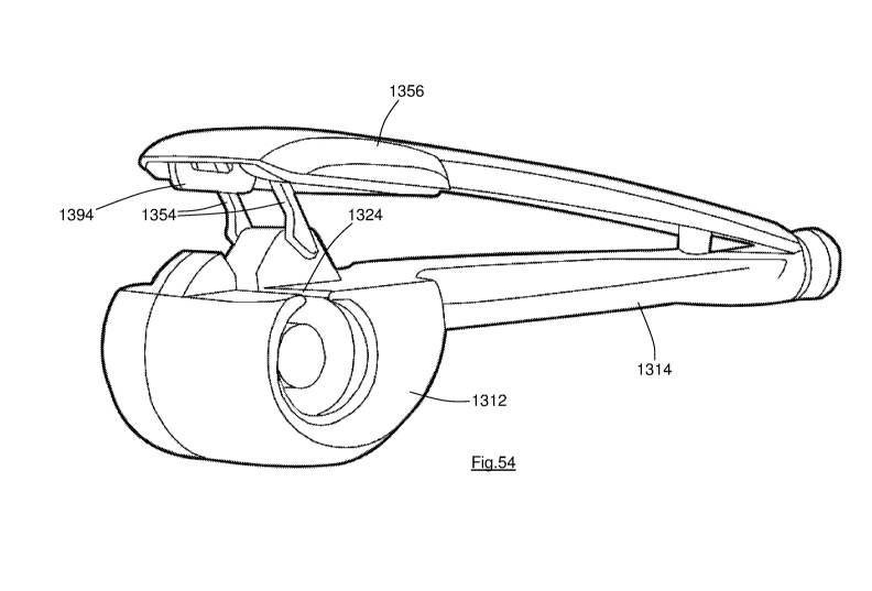
Fig.54 shows a perspective view of another embodiment according to the second
aspect;
Fig.55 shows another perspective view of the embodiment of Fig.54; and
Figs. 56-59 show a sequence of operations of the embodiment of Figs. 54 and
55.
DETAILED DESCRIPTION
Whilst W02009/077747 is included herein by reference, a brief description of
the
operation of the device is provided in relation to the embodiment of Figs.1-5,
so as to
clarify the distinctions over the previous disclosure.
The hair styling device 110 has a body 112 and a handle 114. Within the body
112 is
a chamber 116. An elongate member 120 is located within the chamber 116, the
diameter 2r of the elongate member 120, and the diameter D of the wall 122 of
the
chamber (see Fig.5), being chosen to produce curls of the desired curvature.
(It will
be understood that the elongate member 120, and the chamber 116, need not be
of
circular cross-section, and so the reference to "diameter" refers only to
those circular
embodiments).
The body 112 has a primary opening 124 (Fig.2) through which a length of hair
126
(Figs. 3,4) may be introduced into the chamber 116. In this embodiment, the
introduction of a length of hair 126 into the device is facilitated by a pair
of inclined
surfaces 130 and 132, which lie to opposed sides of the primary opening 124.
It will
be understood that in other embodiments one or both of the inclined surfaces
is
omitted.
CA 02873335 2014-11-12
WO 2013/186547 PCT/GB2013/051526
12
The device 110 has a rotatable element 134 (which may be identical to the
rotatable
element 1134 which is better shown in the embodiment of Fig.47) which can be
driven to rotate about a longitudinal axis A-A. The rotatable element 134
projects
beyond the primary opening 124, and as seen in Fig.2 the inclined surfaces 130
and
132 have cut-outs formed therein to accommodate the rotatable element 134
during
its rotation.
In this embodiment the axis A-A around which the rotatable element 134 rotates
is
parallel to and coincident with the longitudinal axis of the elongate member
120, but
that is not necessarily the case. Also, in this embodiment the elongate member
120 is
fixed relative to the body 112, i.e. it does not rotate with the rotatable
element 134, but
that is also not necessarily the case, and in other embodiments the elongate
member
rotates with the rotatable element.
As the rotatable element 134 rotates (clockwise as drawn in Fig.1), its
leading edge
128 passes over the length of hair 126 which lies adjacent to the primary
opening 124,
and its leading edge 128 captures the length of hair 126. The form of the
rotatable
element 134 is such that it pulls the length of hair 126 through the primary
opening
124 and into the chamber 116 as it rotates.
Considering the length of hair 126 shown in Fig.3, the end 140 is the free end
of the
length of hair, and the part 142 is connected to the user's head (not shown).
The hair
styling device 110 is intended to impart curls to substantially all of the
length of hair
126 lying between the part 142 and the free end 140, so that the numeral 142
represents the "end" of the length of hair 126 which will be styled by the
device. Each
of the individual hairs in the length of hair 126 will be connected to the
user's scalp
(not shown).
As the rotatable element 134 rotates, the distal portion of the length of hair
126 (which
lies between the rotatable element 134 and the free end 140), is pulled
through the
primary opening 124 to the far side of the rotatable element as drawn in
Fig.2. As
shown in Fig.2, the primary opening 124 has a closed end 148 which provides a
relatively fixed surface and it is the relative rotation between the rotatable
element 134
and the primary opening 124 (and in particular its closed end 148) which
causes the
hair to be drawn into the device 110.
CA 02873335 2014-11-12
WO 2013/186547 PCT/GB2013/051526
13
In this embodiment, the primary opening 124 is connected to a secondary
opening
150. When the rotatable element 134 is rotated, the proximal portion of the
length of
hair (which lies between the rotatable element 134 and the part 142), will
also be
pulled through the primary opening 124 and into the chamber 116, to the near
side of
the rotatable element as viewed in Fig.2. In particular, the proximal portion
is pulled
through the primary opening 124 and into the secondary opening 150.
Though not shown in the drawings, the hair styling device 110 can include an
abutment within the secondary opening 150 which provides a relatively fixed
surface,
and it will be understood that it is the rotation of the rotatable element 134
relative to
the fixed abutment which causes the length of hair to be drawn into the
chamber 116.
In other embodiments, the user is instructed to place a finger or thumb across
the
secondary opening 150, the user's finger or thumb providing the abutment. In
yet
other embodiments, the secondary opening carries a number of projections 152
such
as those shown in Fig.52, or a number of indentations 154 as in the embodiment
of
Fig.53, and the user can manipulate the hair styling device so as to
temporarily trap
the length of hair between projections 152 or within indentations 154.
It is understood that the abutment may not need to remain in position for the
whole of
the styling procedure, and in some cases once the length of hair begins to be
wound
around the elongate member 120 the abutment (such as the user's finger or
thumb for
example) can be removed whilst the rotatable element continues to rotate.
In common with the hair styling devices of W02009/077747, the hair is not
clamped
by any part of the device 110. The part 142 of the length of hair 126 is,
however,
substantially fixed in position relative to the device 110. Accordingly, as
the rotatable
element 134 continues to rotate, the distal portion of the length of hair 126
is gradually
pulled from the far side of the rotatable element 134 to the near side, as
drawn in
Fig.2, until eventually all of the length of hair 126 is wound around the
elongate
member 120 to the near side of the rotatable element 134.
The chamber 116 is heated, in this embodiment by way of heating elements (not
shown) within the elongate member 120 and within the wall 122 of the chamber
116.
CA 02873335 2014-11-12
WO 2013/186547 PCT/GB2013/051526
14
The movable panel 156 is pivotably mounted upon the handle 114, the pivot axis
being relatively close to the chamber 116 (and substantially closer to the
chamber 116
than the pivot axis of the movable panel of W02012/080751) and in this
embodiment
is electrically actuated by way of a switch 160. The switch may be located at
any
suitable location upon the handle 114. In the alternative embodiment of Figs.
6-11
the movable panel is manually actuated by way of a trigger 260 and such a
method
may be used as an alternative to electrical actuation.
The movable panel 156 can be moved relative to the body 112 between the open
position shown in Figs. 2 and 3 and the closed position shown in Figs. 1 and
4. In this
embodiment the movable panel 156 is electrically actuated to move between its
open
and closed positions, but in other embodiments the panel may be resiliently
biased to
one of these positions.
The hair styling device 110 is therefore particularly suited for use by a
person styling
her own hair, the user grasping the length of hair 126 with one hand and
grasping
(and operating) the hair styling device 110 with the other hand. The ability
to grasp
and manipulate the hair styling device 110 with one hand will also be
advantageous
for hairdressers and the like when using the device to style another person's
hair.
As is made clear from Fig.5, the width W of the primary opening 124 is
significantly
larger than the primary opening of the comparable embodiment of Figs. 1-8 of
W02009/077747 and of the embodiment of Figs. 1-5 of W02012/080751.
In particular, the width W of the primary opening 124 is substantially wider
than the
diameter 2r of the elongate member 120. In addition, the primary opening lies
adjacent to the edge of the elongate member 120, i.e. the height h of the
primary
opening above the longitudinal axis A-A of the elongate member 120 is in this
embodiment approximately the same as the radius r of the elongate member. The
user is therefore able to place the length of hair 126 much closer to the
elongate
member 120 (and perhaps into engagement with the elongate member 120) prior to
actuation of the rotatable element 134, with the advantage that the rotatable
element
134 can be smaller, allowing a reduction in the overall size of the device
110,
particularly in the cross-sectional dimension of the body 112.
CA 02873335 2014-11-12
WO 2013/186547 PCT/GB2013/051526
It will be understood that the height h of the primary opening 124 above the
longitudinal axis A-A of the rotatable element can in other embodiments be
less than,
or greater than, the radius r of the elongate member. Also, the width W of the
primary
5 opening 124 can be reduced from that shown in Fig.5, to approximately the
same as
the width 2r of the elongate member.
Because the primary opening 124 spans a large proportion of the
circumferential
length of the wall of the chamber 116, the panel 156 is heated by way of a
heater
10 element 158 mounted in engagement with the heat-conductive wall 162 of
the panel
156. In the closed position of the panel heat can therefore be applied to the
length of
hair within the chamber 116 around substantially the full circumference of the
chamber
116 (and along substantially the full length of the chamber 116).
15 In the embodiment of Figs. 1-5 the movable panel 156 provides the dual
function of
covering the rotatable element 134 and closing the primary opening 124. The
movable panel 156 spans the full length of the chamber 116 so that the maximum
quantity of heat can be delivered into the chamber. It will be understood that
in
embodiments according to other aspects of the invention (in which the movable
panel
is not heated for example) it is not necessary that the panel spans the full
length of the
chamber.
When the length of hair 126 has been styled, for example by remaining within
the
heated chamber 116 for a predetermined length of time, the curled length of
hair 126
can be slid off the end of the elongate member 120, through the secondary
opening
150 (the abutment within the secondary opening being moved if necessary).
Little
force is required to separate the hair styling device 110 from the length of
hair which
has been styled, and because the secondary opening 150 surrounds the elongate
member 120 the length of hair is not required to pass any obstruction or
otherwise be
forced to uncurl during its removal from the hair styling device 110, so that
the
curvature of the curls created by the device can be substantially maintained.
It has been recognised that the most significant likelihood of entanglement of
the
length of hair 126 is caused by a portion of the length of hair 126 being
captured by
the rotatable element, and another portion of the length of hair 126 not being
captured
CA 02873335 2014-11-12
WO 2013/186547 PCT/GB2013/051526
16
by the rotatable element. In such circumstances the captured portion becomes
wound
around the elongate member whereas the uncaptured portion does not.
Embodiments
of the present invention which seek to reduce the likelihood of such
entanglement by
increasing the likelihood that all of the length of hair 126 is captured by
the rotatable
element are shown in Figs. 6-11, Figs. 12-15, Figs. 16-18, Figs. 19-20, Figs.
21-28,
Figs. 29-33 and Figs. 54-49.
In addition to the optional inclusion of fixed inclined surfaces which serve
to guide the
length of hair towards the primary opening, these drawings show various
embodiments of a movable guide part 254 (etc.) which serve primarily to block
the gap
beyond the primary opening and guide the length of hair towards the primary
opening.
However, in the embodiments shown the guide parts also serve the secondary
function of pressing the length of hair towards the primary opening. In
particular, the
movable guide part 254 etc. serves to press the length of hair below the
leading edge
of the rotatable element, so as to reduce the likelihood that some of the
length of hair
is not captured by the rotatable element.
In the embodiment of Figs. 6-11, the guide part 254 is generally in the form
of a U-
shaped element which is pivotably mounted upon the body 212. The base of the U-
shaped element is located within a pocket 270 (Fig.10) of a movable panel 256,
the
movable panel being pivotably mounted upon the handle 214. The guide part 254
is
therefore mounted to move with the movable panel 256, but some relative
movement
must be accommodated because of the differing pivot positions.
The movable panel 256 is resiliently biased to its open position (Figs. 6 and
8), and
the user moves the panel 256 to its closed position by pressing a pivoting
trigger 260
towards the handle 214.
In the drawings the handle 214 and the trigger 260 are curved, but they could
be linear
as in other embodiments.
As in the embodiment of Figs. 1-5, the movable panel 256 serves both to cover
the
rotatable element 234 in use, and also carries a heating element (not shown)
to heat
the chamber 216.
CA 02873335 2014-11-12
WO 2013/186547 PCT/GB2013/051526
17
In the embodiment of Figs. 12-15, the guide part 354 is separate from the
movable
panel 356, the guide part 354 being moved to its closed or operational
position as
shown in Fig.14 prior to the panel 356 being moved to its closed position as
shown in
Fig. 15. The step of the guide part 354 pressing the length of hair towards
the primary
opening 324 is therefore separate from the step of covering the rotatable
element 334.
In Fig. 15 the arrows show the circular path 372 of the leading edge 328 of
the
rotatable element. It will be apparent from Figs. 14 and 15 that it is
arranged that
when the guide part 354 is in its closed position it lies close to the primary
opening
324, and importantly within the circular path 372. The guide part 354 (and
similarly
the guide parts of the other embodiments) acts firstly to guide the length of
hair
towards the primary opening, and secondly to press the length of hair below
the
circular path taken by the leading edge 328 of the rotatable element 334 so as
to
ensure that all of the length of hair is captured by the rotatable element.
Also in common with the other embodiments, the movable panel 356 covers and
encloses the rotatable element 334 so as to prevent stray hair being engaged
by the
rotatable element. It is therefore desirably arranged that, in common with
other
embodiments, the rotatable element 334 cannot be rotated until the guide part
354
and the movable panel 356 are in their operative or closed positions shown in
Fig.15.
The primary function of the guide parts 254, 354 (etc.) is most apparent from
Figs. 8
and 12 (and also Fig.54), namely blocking the gap between the body and the
movable
panel beyond the primary opening and thereby guiding the length of hair
towards the
primary opening 224, 324. It will be apparent that when a length of hair is
pushed into
the gap between the body 212, 312 and the movable panel 256, 356 respectively,
it
engages the respective guide part 254, 354 so that the guide part prevents any
hair
being pushed into an area beyond the primary opening where it might become
trapped
between the body and the movable panel as the movable panel is closed. The
angled
orientation of the guide part 254, 354 above the primary opening causes the
length of
hair to be positively guided towards the primary opening. It will be
understood that the
angled arrangement of the guide part is preferable but not essential; provided
the
guide part blocks the gap beyond the primary opening it can be used to guide
the
length of hair towards the primary opening.
CA 02873335 2014-11-12
WO 2013/186547 PCT/GB2013/051526
18
In common with the rear inclined surface disclosed in W02012/080751, it is an
important function of the guide part 254, 354 etc. to reduce the likelihood
that any part
of the length of hair is inadvertently pushed beyond the primary opening where
it may
potentially become trapped between the body and the movable panel.
In
W02012/080751 this is achieved by making the range of movement of the movable
panel smaller than is necessary for the movable panel to clear the top of the
inclined
surface (or alternatively stated by making the inclined surface large enough
to lie
within the movable panel when the movable panel is fully opened). Effectively
therefore the rear inclined surface of W02012/080751 blocks the gap which
exists
between the body and the movable panel beyond the primary opening, and thereby
prevents hair being inadvertently pushed beyond the primary opening. The
advantage
of a movable guide part is that the movable guide part can be used to block
the gap
beyond the primary opening and it is not necessary to provide a fixed surface
to block
the gap. The movable panel may therefore be moved beyond the height of the
fixed
inclined surface, thereby increasing the size of the gap into which the length
of hair
may be introduced (this feature is most clearly shown in the embodiment of
Fig.54).
Alternatively or additionally, the inclined surface may be made smaller
without limiting
the range of movement of the movable panel. Since the movable panel must
accommodate the inclined surface in its closed position, a smaller inclined
surface
facilitates a smaller (and in particular a thinner) movable panel and thereby
a smaller
hair styling device.
The blocking and guiding functions of the guide part are enhanced because the
pivot
axis of the guide part 254, 354 (etc.) is located close to (and in particular
immediately
adjacent to) the primary opening.
In the embodiment of Figs. 12-15 the body 312 has an inclined surface 330 upon
which the guide part 354 is mounted. Depending upon the mounting location of
the
guide part, the inclined surface can cooperate with the guide part in
physically
preventing any of the length of hair being inadvertently pushed by the user
beyond the
primary opening. It is apparent from Fig.10 that in this embodiment the guide
part is
mounted so close to the primary opening that only a small part of the inclined
surface
can be engaged by the length of hair. The inclined surface can therefore be
very
small, as can the recess within the movable panel 256 which is provided to
accommodate the inclined surface.
CA 02873335 2014-11-12
WO 2013/186547 PCT/GB2013/051526
19
The embodiment of Figs. 12-15 includes another fixed inclined surface 332
which
serves to guide the length of hair towards the primary opening 324. The sides
of the
guide part 354 are spaced apart along the longitudinal axis A-A by a distance
only
slightly greater than the width of the inclined surface 332, so that in the
closed position
the guide part closely surrounds the inclined surface 332.
It will therefore be understood that any of the length of hair lying adjacent
to the
inclined surface 332 when the guide part 354 and panel 356 are in their open
position
(Fig. 12), will be pressed by the guide part 354 along the inclined surface
332 towards
the primary opening 324 as the guide part 354 is moved to its closed position.
The
length of hair will therefore be held adjacent to the primary opening 324 as
the
rotatable element begins to rotate, whereby the likelihood of any portion of
the length
of hair not being captured by the rotatable element 334 is much reduced or
eliminated.
The alternative embodiment of Figs. 16-18 has two guide parts 454a and 454b
which
can move from their open position shown in Fig.16, through their intermediate
position
of Fig.17, to their closed position of Fig.18, during which movement the guide
parts
engage the length of hair and press it towards the primary opening.
Once again, the guide parts 454a,b are U-shaped, and it will be understood
that the
base of each U-shaped guide part must lie outside the circular path of the
leading
edge of the rotatable element (so that they do not foul the rotatable
element), whilst
the sides of the guide parts lie within the circular path.
The guide parts 454a,b are electrically actuated in this embodiment, but could
be
made mechanically actuated if desired.
The embodiment of Figs. 19 and 20 is somewhat similar to that of Figs. 16-18,
except
that this device includes a single guide part 554 and a cooperating movable
(and
heated) panel 556.
The embodiment of Figs. 21-28 has a first guide part 654 comprising two
fingers 654a,
654b, which effectively comprise the sides of the U-shaped guide part of the
earlier
CA 02873335 2014-11-12
WO 2013/186547 PCT/GB2013/051526
embodiments, without the base. This embodiment also has one fixed inclined
surface
630 and a second guide part in the form of a movable inclined surface 632.
Figs. 21-24 show side views of the sequence of operations of the device 610,
and
5 Figs. 25-28 show the sequence in perspective view. It will be observed that
the
inclined surface 632 moves from its open or retracted position of Figs. 21 and
25, to its
closed or extended position of Figs. 24 and 28, as the guide parts 654a,b are
moved
to their closed positions.
10 Figs. 29-33 show views of an embodiment using a different form of guide
part 754. In
this embodiment the guiding function of the guide part 754 is less significant
than its
pressing function. The guide part 754 is shown in Fig.31, and comprises a
bifurcated
member which can pivot about an axle 774. The rotatable element 734 (the
circular
path 772 of the leading edge of which is shown in dotted outline in Figs. 29
and 30)
15 can pass between the two side parts 776a and 776b of the guide part 754.
The device 710 is electrically actuated, and includes a drive member 778 which
can
move between a retracted position shown in Fig.30 and an extended position
shown in
Fig.29. In the retracted position the guide part 754 is resiliently biased to
its open
20 position and in the extended position the drive member 778 drives the
guide part 754
to its closed position.
The device 710 also includes a movable abutment 752 which is similarly pivoted
between its open and closed positions by the drive member 778.
It will be understood that the guide part of certain embodiments is generally
interchangeable with the guide part of other embodiments, and similarly for
the means
of moving the guide part. It will also be understood that the guide part
provides its
guiding function primarily during the initial stage of operation in which the
length of hair
is introduced into the device by the user (during which stage the guide part
is
substantially stationary). The guide part provides its pressing function in
the
subsequent stage of operation during which the guide part moves towards the
primary
opening.
CA 02873335 2014-11-12
WO 2013/186547 PCT/GB2013/051526
21
The embodiment of Figs. 34-36 has two movable cover elements 880, 882 for the
rotatable element 834. The movable cover elements 880, 882 can move between an
open position as shown in Fig.34, through an intermediate position shown in
Fig.35, to
a closed position as shown in Fig.36. It will be observed that in the open
position the
rotatable element 834 is exposed, whereas in the closed position the rotatable
element 834 is covered by the movable cover elements 880, 882. The cover
element
880 is smaller than the cover element 882, and in the closed position the
cover
element 882 overlies (and covers) a part of the cover element 880.
In addition, as seen in Fig.35, the movable cover elements 880, 882 have
respective
leading edges which act to press a length of hair towards the primary opening
824 as
they move to their closed position. The movable cover elements in this
embodiment
therefore act both as pressing parts to urge the length of hair towards the
primary
opening and as a cover for the rotatable element. In an alternative embodiment
in
which the cover elements move only between the positions show in Figs. 35 and
36
they can provide an initial guiding function also.
In each of the embodiments of Figs. 1-36 the pivot axis of the movable panel
and/ or
the pivot axis of the pressing part(s) is parallel (or substantially parallel)
to the
longitudinal axis A-A of the elongate member. In other embodiments the pivot
axis of
the movable panel, and/or the pivot axis of the pressing part(s) is at an
angle to the
elongate member.
In the preferred embodiments in which the rotatable element is a substantially
planar
disc, it is desirable that the rotatable element rotate about an axis which is
substantially parallel to the longitudinal axis of the elongate member A-A.
Arranging
the pivot axis of the pressing part to be substantially parallel to the
longitudinal axis A-
A, and therefore substantially parallel to the axis of rotation of the
rotatable element,
results in the pressing part moving about an axis which is substantially
perpendicular
to the plane of the disc, whereby the pressing part can move along a path
close to, but
not engaging, the rotatable element.
In the embodiment of Figs. 37 and 38 the body 912 is formed from two body
parts
912a, 912b which are hinged to one another by way of a hinge 984.
CA 02873335 2014-11-12
WO 2013/186547 PCT/GB2013/051526
22
Each of the body parts 912a,b has a respective flange 986 which in the open
position
of Fig.37 are inclined and serve to guide a length of hair towards the primary
opening
924. In the closed position of Fig.38 the flanges 986 engage one another so
that the
primary opening is fully closed before the rotatable element 934 begins to
rotate.
Each of the body parts 912a,b has a groove 986 which accommodates the
rotatable
element 934. Each of the body parts 912a,b can carry a respective heating
element if
desired.
The body parts 912a,b are substantially mirror-images of one another in this
embodiment, but it will be understood that mirror-image body parts are not
required to
form a body such as 912.
Figs. 37 and 38 show the preferred embodiment in which the axis of the hinge
984 is
parallel (or substantially parallel) to the longitudinal axis A-A of the
elongate member,
but in other embodiments the hinge axis is arranged at an angle to the
longitudinal
axis of the elongate member.
The embodiment of Figs. 39-43 has a two-part rotatable element 1034,
comprising a
first part 1034a and a second part 1034b. Prior to operation of the device
1010 the
first part 1034a and the second part 1034b adopt an open position as shown in
Figs.
39 and 41. In that condition the rotatable element 1034 provides an open-ended
aperture 1088 into which a length of hair can be inserted by the user (and/or
pressed
by the pressing part of the device if present).
When the length of hair has been placed or pressed into the open-ended
aperture
1088, the parts 1034a,b contra-rotate, and move through the intermediate
position of
Fig.42 to the closed position of Figs. 40 and 43. In the closed position the
aperture
1088 is fully or substantially closed. Any hair located therein is retained
within the
aperture 1088 and stray hair cannot enter the aperture. The rotatable element
1034 is
then rotated (either clockwise or anti-clockwise as desired), with the parts
1034a,b
rotating together to maintain the closed aperture 1088.
Since the closed aperture 1088 prevents the rotatable element 1034 from
capturing
stray hair the likelihood of entanglement is reduced or avoided, and this
embodiment
CA 02873335 2014-11-12
WO 2013/186547 PCT/GB2013/051526
23
may therefore be used without a cover or panel for the rotatable element.
However, a
cover may nevertheless be desired by certain users.
It will be understood that contra-rotation of the parts 1034a and b is not
required to
close the aperture 1088, and only one of the parts 1034a,b need be rotated to
close
the aperture. Once the aperture 1088 is closed the parts 1034a,b rotate
together to
curl the length of hair around the elongate member 1020.
Figs. 44-48 show an embodiment utilising a closure element according to the
sixth
aspect of the invention. According to this aspect, a pressing part to press
the length of
hair towards the primary opening 1124 is not provided. Instead, the closure
element
1190 is provided coincident with the circular path 1172 of the leading edges
1128 of
the rotatable element 1134. By arranging the closure element 1190 at this
location,
and providing a tapered leading end 1192, the closure element 1190 can move
hair
both towards and away from the elongate member 1120, as required.
Specifically,
hair which is located within the circular path 1172 of the leading edge 1128
of the
rotatable element 1134 is driven towards the elongate member 1120 (i.e.
towards or
further into the primary opening 1124), whereas hair which is located outside
the
circular path 1172 is pushed away from the elongate member 1120. In this way,
the
length of hair is divided into a first portion which will be captured by the
rotatable
element 1134 and a second portion which will not be captured. The first
portion is
pushed into the chamber 1116 as the rotatable element rotates. The second
portion is
held away from the rotatable element by the closure element 1190 for the
duration of
the styling operation.
It will be observed that the rotatable element 1134 has two leading edges
1128, and
this is common to all of the embodiments described. The rotatable element can
therefore capture the length of hair whether it is rotated clockwise or anti-
clockwise.
Figs. 49-51 show optional "doors" 1292 to span the primary opening 1224. In
Fig.49
the length of hair 1226 is located adjacent to the doors, which in this
embodiment are
flexible and resilient. The length of hair 1226 may therefore be pressed
through the
doors 1292 and into the chamber 1216 as shown in Fig.50. Alternatively, the
doors
may be inflexible, but resiliently mounted to pivot between their open and
closed
positions. It can if desired be arranged that the doors retain the length of
hair within
CA 02873335 2014-11-12
WO 2013/186547 PCT/GB2013/051526
24
the chamber 1216, i.e. they allow hair to pass into the chamber 1216 but not
out of the
chamber.
In the embodiments of Figs. 6-36 the guide part performs the function of
pressing the
length of hair towards the primary opening. In the alternative embodiment of
Figs. 54-
59 there is a separate pressing part 1394 in addition to the guide parts 1354.
The
pressing part 1394 is carried by the movable panel 1356 and this arrangement
is
particularly beneficial because the path of movement of the pressing part 1394
is
almost directly towards the primary opening.
Thus, it will be understood that the movable panel 1356 pivots relative to the
body
about a pivot axis located at the opposite end of the handle 1314 to the body
1312.
The guide parts 1354 also pivot relative to the body 1312, the pivot axis P-P
(Fig.55)
of the guide parts 1354 being almost immediately adjacent to the primary
opening
1324. The pressing part 1394 therefore moves through a much smaller angle than
the
guide parts 1354 during the closing movement of the movable panel 1356. This
minimises any tendency to push the length of hair away from the primary
opening.
It will be understood from the sequence of operations shown in Figs.56-59 that
during
the initial closing movement of the movable panel 1356 the length of hair will
likely be
engaged by the guide parts 1354 and pressed towards the primary opening. By
the
time the movable panel 1356 has moved to the position of Fig.58, however, the
length
of hair is being pressed towards the primary opening substantially entirely by
the
pressing part 1394.
Fig.55 shows the underside of the movable panel 1356, and in particular the
connection between the guide parts 1354 and the movable panel. In this
embodiment
both guide parts 1354 are formed as parts of an integral construction in a
general U-
shape, with the base of the U lying along the pivot axis P-P. The end of one
guide
part 1354 is located in a pocket or channel 1370 in the movable panel 1356, so
that
the guide parts 1354 are lifted up and pressed down by movement of the movable
panel 1356. In another embodiment the guide parts 1354 are resiliently biased
towards the position of Figs.54-56, and in yet other embodiments they also act
to drive
the movable panel 1356 to the open position.
CA 02873335 2014-11-12
WO 2013/186547 PCT/GB2013/051526
Figs.54 and 56 in particular show that the movable panel 1356 can be opened
well
beyond the height of the inclined surface 1330, so that the thickness of the
movable
panel 1356 (i.e. the dimension in the vertical direction as drawn) can be much
reduced
over the embodiment of W02012/080751 which utilises fixed guide parts.
5
It will be understood that in other embodiments the guide part(s) can be
movable
without pivoting, i.e. the guide part(s) may be adapted to slide within a
channel, or be
made sufficiently flexible to move by bending, for example.
In addition, in
embodiments similar to that of Figs. 21-28 the second guide part (i.e. the
inclined
10 surface ahead of the primary opening) could be made flexible to move by
bending.
The flexible guide part(s) are preferably deformed as they are engaged by the
movable panel.
In a modification of the embodiment of Figs. 1-5, the device could be adapted
to
15 dispense a hair treatment product onto the length of hair. The
dispensing of a hair
treatment product, for example a heat protective product, is discussed in
W02009/077747. In the present invention, the product could be dispensed from
the
movable panel 156. In a particularly advantageous embodiment, the hair
treatment
product could be held within a tank within the movable panel 156, the tank
being
20 sufficiently close to the heater 158 so that the treatment product is
heated (and ideally
vaporised) within the tank before passing out of the movable panel and
engaging the
length of hair.
The hair treatment product could be dispensed directly into the chamber
surrounding
25 the elongate member, or it could if desired be arranged that the
treatment product
engages the hair before it enters the chamber, so that the hair is pre-heated
before
entering the chamber. The length of hair would then likely need to remain
within the
chamber for a shorter period of time than would otherwise be necessary whilst
the curl
is set. If desired, a heater (in addition to the heater 158) could be provided
to heat the
length of hair before it enters the chamber, so that the (vaporised) treatment
product
and the additional heater act together to pre-heat the hair before it enters
the chamber
where the curl is set.
In common with the device disclosed in W02009/077747, the rotatable element
may
be connected to a cylindrical hub which rotates with the rotatable element.
The
CA 02873335 2014-11-12
WO 2013/186547 PCT/GB2013/051526
26
rotatable element lies between the hub and the chamber, and a section of the
length
of hair will be wound around the hub during the initial rotations of the
rotatable element
(see for example Fig.5B of W02009/077747). If desired, a sleeve which does not
rotate with the hub may be provided around the rotating hub so as to avoid the
force
which would otherwise be applied to the length of hair as the hub rotates. The
sleeve
could be freely mounted so that it is able to rotate in either direction,
which could be
advantageous in permitting forced removal of the hair if necessary.
Alternatively a
non-rotatable sleeve could be mounted to the body of the device, such a sleeve
being
readily adaptable to incorporate a heater to pre-heat the length of hair
before it enters
the chamber.