Note: Descriptions are shown in the official language in which they were submitted.
CA 02873691 2016-04-20
ELECTRO PLATING DEVICE
[Technical Field]
[0001]
The present invention relates to an electro plating device which forms an
electro plating layer on a surface of a female screw carved on an inner
circumferential
surface of a pipe end of a steel pipe.
[Background Art]
[0002]
In order to collect natural gas or crude oil from underground, a pit is dug
toward a natural gas field or an oil field existing at several thousand meters
from the
ground surface to underground, and it is necessary to install a large
transport pipe to
the pit. In the transport pipe, a plurality of long steel pipes (so-called oil-
well pipes)
are connected to each other in a line. In recent years, in the viewpoint of
productivity
improvement, a need for a screw joint (so-called integral joint) for a steel
pipe capable
of directly connecting the oil-well pipes without using a coupling is
increasing. The
oil-well pipe having a male screw formed on an outer circumferential surface
of one
pipe end and a female screw formed on an inner circumferential surface of the
other
pipe end is used as the integral joint. That is, the integral joint includes
the male
screw (pin) which is spirally carved on the outer circumferential surface of
one pipe
end of the oil-well pipe, and the female screw (box) which is spirally carved
on the
inner circumferential surface of one pipe end of the other oil-well pipe
connected to the
oil-well pipe.
- 1 -
CA 02873691 2014-11-13
[0003]
Conventionally, when the oil-well pipes are secured to each other, in order to
prevent seizure of the joint portion, lubricating oil (API dope) including
heavy metals
such as Pb is applied to at least one of the male screw and the female screw
of the oil-
well pipe. On the other hand, in a region in which use of the API dope is
limited
under a severe environmental regulation, environment protective lubricating
oil (green
dope) not including heavy metals may be used. Since lubricity of the green
dope is
worse than that of the API dope, the seizure easily occurs in the joint
portion.
Thereby, when the green dope is used as the lubricating oil, in order to
compensate for
lack of the lubricity of the green dope and prevent occurrence of the seizure,
it is
preferable that an electro plating layer such as copper be formed on at least
one surface
of the male screw and the female screw carved on the pipe end of the oil-well
pipe.
[0004]
For example, in Patent Document 1 below, a device is disclosed which forms
an electro plating layer on a surface of a male screw (pin) carved on one pipe
end of
the oil-well pipe, that is, on an outer circumferential surface of one pipe
end of the oil-
well pipe.
[Prior Art Document]
[Patent Document]
[0005]
[Patent Document 1] Japanese Examined Patent Application, Second
Publication No. S63-6637
[Disclosure of the Invention]
[Problem that the Invention is to solve]
[0006]
- 2 -
CA 02873691 2014-11-13
When a coupling is used as a joint element, an electro plating layer is formed
on a surface of a female screw carved on an inner circumferential surface of
the
coupling, and thus, reliability (seizure resistance) of a joint portion is
improved. Also
in an integral joint, in order to obtain the similar reliability, it is
preferable that an
electro plating layer be formed on a surface of a female screw (box) carved on
an inner
circumferential surface of one pipe end of an oil-well pipe.
[0007]
In general, when the electro plating layer is formed, bubbles of hydrogen or
oxygen are generated concurrently with the electro plating layer. As described
in
Patent Document 1, when the electro plating layer is formed on the surface of
the male
screw carved on the outer circumferential surface of the steel pipe, since
bubbles are
rapidly separated from the surface of the male screw, there is no problem.
However,
when the electro plating layer is formed on the surface of the female screw
carved on
the inner circumferential surface of the steel pipe, since separation of the
bubbles is
impeded due to an inner wall of the steel pipe, particularly, the bubbles
easily remain
in grooves of the female screw. The residual portion of the bubbles becomes an
unplated region and becomes the cause which decreases seizure resistance of
the joint
portion.
[0008]
The present invention is made in consideration of the above-described
circumstance, and an object thereof is to provide an electro plating device
capable of
forming a uniform electro plating layer without an unplated region on the
surface of
the female screw carved on the inner circumferential surface of the pipe end
of the
steel pipe.
[Means for Solving the Problems]
- 3 -
CA 02873691 2014-11-13
=
[0009]
The present invention adopts the following means in order to solve the above-
described problems and achieve the related object. That is,
(1) According to an aspect of the present invention, there is provided an
electro plating device which forms an electro plating layer on a surface of a
female
screw carved on an inner circumferential surface of a pipe end of a steel
pipe,
including: a pipe inside seal mechanism which occludes an inner channel of the
steel
pipe at a position distanced from the female screw in a pipe axial direction
of the steel
pipe; a tubular insoluble electrode which is disposed in the pipe end so as to
be
opposite to the female screw; a plating solution feed mechanism which includes
a
plurality of nozzles which extend radially with a pipe axis of the steel pipe
as a center
and is disposed outside the pipe end; and a pipe end seal mechanism which
accommodates the nozzles thereinside and is mounted to the pipe end in a state
where
the pipe end seal mechanism closely contacts an outer circumferential surface
of the
pipe end, and when viewed in the pipe axial direction, a tip of each of the
nozzles is
positioned between the female screw and the insoluble electrode, and each of
the
nozzles injects the plating solution from an injection port formed on the tip
toward a
direction which intersects an extension direction of the nozzle, the direction
being a
rotational direction of a clockwise direction or a counterclockwise direction
in which
the pipe axis is the center.
[0010]
(2) In the electro plating device according to (1), each of the nozzles may
be
perpendicular to the pipe axial direction or be inclined toward the pipe end
side.
[0011]
(3) In the electro plating device according to (1), each of the nozzles may
be
- 4 -
CA 02873691 2014-11-13
perpendicular to the pipe axial direction, and each of the nozzles may inject
the plating
solution in a reference direction perpendicular to the pipe axial direction
and the
extension direction when viewed in the extension direction of the nozzle or
inject the
plating solution in a direction which is inclined from the reference direction
to the pipe
end side.
[0012]
(4) In the electro plating device according to any one of (1) to (3), the
plating solution feed mechanism may include three nozzles.
[0013]
(5) In the electro plating device according to any one of (1) to (4), the
pipe
end seal mechanism may further include: a discharging port for discharging a
used
plating solution; and a liquid discharge promotion mechanism for promoting
discharging of the used plating solution.
[0014]
(6) In the electro plating device according to (5), the liquid discharge
promotion mechanism may be an atmosphere opening portion which is disposed at
a
position above the steel pipe in the pipe end seal mechanism.
[Effects of the Invention]
[0015]
According to the above-described aspects, a uniform electro plating layer can
be formed without an unplated region on the surface of the female screw carved
on the
inner circumferential surface of the pipe end of the steel pipe.
[Brief Description of the Drawing]
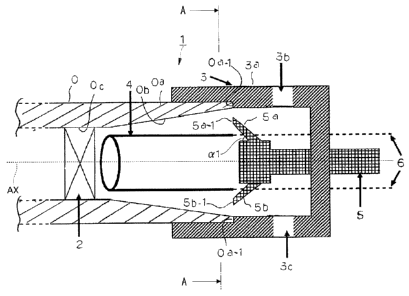
[0016]
FIG. 1 is an explanatory view conceptually showing a configuration of an
- 5 -
CA 02873691 2014-11-13
=
=
electro plating device according to an embodiment of the present invention.
FIG. 2 is a cross-section view taken along line A-A of FIG. 1 (a view when
viewed in a pipe axial direction of a steel pipe 0).
FIG. 3 is a view when a plating solution feed mechanism 7 in modification
example is viewed in a direction perpendicular to the pipe axial direction of
the steel
pipe 0.
FIG. 4 is a cross-section view taken along line B-B of FIG. 3 (a view when
viewed in a pipe axial direction of a steel pipe 0).
FIG. 5 is a view when a plating solution injection nozzle 7a is viewed in an
extension direction R11 thereof
[Best Mode for Carrying Out the Invention]
[0017]
Hereinafter, an embodiment of the present invention will be described in
detail with reference to drawings or the like.
FIG. 1 is an explanatory view conceptually showing a configuration of an
electro plating device 1 according to an embodiment of the present invention.
[0018]
As shown in FIG 1, the electro plating device 1 according to the present
embodiment is a device which forms an electro plating layer on a surface of a
female
screw Ob spirally carved on an inner circumferential surface of one pipe end
Oa of a
cylindrical steel pipe 0. In FIG. 1, a state where the steel pipe 0 is
disposed
approximately horizontally is exemplified. In descriptions below, a case where
the
steel pipe 0 is a long seamless oil-well pipe is exemplified. Moreover, a
reference
numeral AX in the drawing indicates a pipe axis (central axis) of the steel
pipe 0.
[0019]
- 6 -
CA 02873691 2014-11-13
0
=
The electro plating device 1 includes a pipe inside seal mechanism 2, a pipe
end seal mechanism 3, an insoluble electrode 4, and a plating solution feed
mechanism
5. Hereinafter, the details of each component of the electro plating
device 1 will be
described sequentially.
[0020]
[Pipe Inside Seal Mechanism 2]
The pipe inside seal mechanism 2 is disposed at a predetermined position Oc
inside in a pipe axial direction (a direction along the pipe axis AX in FIG.
1) of the
steel pipe 0 from a female screw Ob of the steel pipe 0. The pipe inside seal
mechanism 2 contacts the steel pipe 0 in a sealing state at the predetermined
position
Oc. In other words, the pipe inside seal mechanism 2 occludes an inner
channel of the
steel pipe 0 at the predetermined position Oc.
[0021]
For example, as the pipe inside seal mechanism 2, a hex plug which is used in
piping work may be used. As is well known, the hex plug has a structure which
occludes an inner channel of a tubular member by inserting a rubber ring
between two
plates and expanding the diameter of the rubber ring. Moreover, the pipe
inside seal
mechanism 2 is not limited to the hex plug and may be any device if having a
structure
capable of occluding the inner channel of the steel pipe 0.
[0022]
Since the pipe inside seal mechanism 2 is well known by a person skilled in
the art, further descriptions with respect to the pipe inside seal mechanism 2
are
omitted.
[0023]
[Pipe End Seal Mechanism 3]
- 7 -
CA 02873691 2014-11-13
=
=
The pipe end seal mechanism 3 includes a tubular main body 3a which
accommodates plating solution injection nozzles 5a, 5b, and Sc included in the
plating
solution feed mechanism 5 described below thereinside and includes an inner
surface
shape which can be mounted in a state where the main body 3a closely contacts
an
outer circumferential surface and an end surface of the pipe end Oa of the
steel pipe 0.
[0024]
The pipe end seal mechanism 3 is mounted to the pipe end Oa in the state
where the main body 3a closely contacts the outer circumferential surface and
the end
surface of the pipe end Oa of the steel pipe 0, and thus, the pipe end seal
mechanism 3
seals the inside of the pipe end Oa of the steel pipe 0 along with the pipe
inside seal
mechanism 2.
[0025]
A liquid discharge port 3c and a liquid discharge promotion mechanism 3b are
disposed in the main body 3a of the pipe end seal mechanism 3.
The liquid discharge port 3c discharges plating solution after the plating
solution is used for formation of the electro plating layer, and is disposed
at a position
lower than the steel pipe 0 when the pipe end seal mechanism 3 is mounted to
the steel
pipe 0.
[0026]
The liquid discharge promotion mechanism 3b promotes discharging of used
plating solution. The liquid discharge promotion mechanism 3b is not limited
to a
specific type if it can promote the discharging of the plating solution, and
as shown in
FIG. 1, is preferably an atmosphere opening port 3b which is disposed at a
position
above the steel pipe 0 in the pipe end seal mechanism 3.
[0027]
- 8 -
CA 02873691 2014-11-13
A configuration may be adopted in which an electromagnetic valve (not
shown) is disposed at the atmosphere opening port 3b and the atmosphere
opening port
3b is opened and closed. Alternatively, a hose is mounted to the atmosphere
opening
port 3b, the hose is extended upward, and it may prevent the liquid from being
blown
outside the main body 3a by balancing pressure of liquid inserted by a pump
and the
weight of the liquid itself. Alternatively, the discharging of the used
plating solution
may be promoted by feeding compressed air from the atmosphere opening port 3b
to
the inner portion of the pipe end Oa, or the like.
[0028]
If the used plating solution is not rapidly discharged after the electro
plating
layer is formed, the electro plating layer may corrode and color of the layer
may be
changed. However, as described above, since the atmosphere opening port 3b is
provided in the pipe end seal mechanism 3 and thus, the used plating solution
is rapidly
discharged, the change of color of the surface of the electro plating layer
formed on the
female screw Ob can be suppressed.
[0029]
[Insoluble Electrode 4]
The insoluble electrode 4 is a hollow cylindrical electrode (anode) for
forming
the electro plating layer on the female screw Ob and is disposed in the pipe
end Oa of
the steel pipe 0 so as to be opposite to the female screw Ob. It is preferable
that the
central axis of the insoluble electrode 4 be disposed so as to coincide with
the pipe axis
AX of the steel pipe 0. That is, when viewed in the pipe axial direction of
the steel
pipe 0, it is preferable that the steel pipe 0 and the insoluble electrode 4
have a
concentric relationship. The insoluble electrode 4 is disposed in this way,
and thus,
an electro plating layer having high uniformity can be formed on the surface
of the
- 9 -
CA 02873691 2014-11-13
female screw Ob which is carved on the inner circumferential surface of the
pipe end
Oa.
[0030]
As the insoluble electrode 4, it is preferable that an electrode, in which an
iridium oxide coating titanium plate or stainless steel plate, or the like is
formed in a
cylindrical shape, be used.
[0031]
An energizing bar 6 for energizing the insoluble electrode 4 penetrates the
main body 3a of the pipe end seal mechanism 3 and is connected to the
insoluble
electrode 4. For example, a titanium bar, a stainless steel bar, or the like
may be used
as the energizing bar 6.
[0032]
If a potential difference is applied between the insoluble electrode 4 and the
steel pipe 0 while the plating solution is supplied between the female screw
Ob and the
insoluble electrode 4 by the plating solution feed mechanism 5 described
below, the
electro plating layer is formed on the surface of the female screw Ob.
[0033]
Since the insoluble electrode 4 is well known by a person skilled in the art,
further descriptions with respect to the insoluble electrode 4 are omitted.
[0034]
[Plating Solution Feed Mechanism 5]
The plating solution feed mechanism 5 supplies the plating solution to the
inside of the pipe end Oa of the steel pipe 0 and is supported at a position
outside the
pipe end Oa by a supporting mechanism (not shown) which is provided on the
pipe end
seal mechanism 3.
- 10 -
CA 02873691 2014-11-13
Hereinafter, a configuration of the plating solution feed mechanism 5 will be
described in detail with reference to FIGS. 1 and 2. Moreover, FIG 2 is a
cross-
section view taken along line A-A of FIG. 1 (that is, a view when is viewed
outside of
the steel pipe 0 from inside of the steel pipe 0 in the pipe axial direction
of the steel
pipe 0).
[0035]
As shown in FIGS. 1 and 2, the plating solution feed mechanism 5 includes a
plurality of (three as an example in the present embodiment) plating solution
injection
nozzles 5a, 5b, and Sc which extend radially with the pipe axis AX of the
steel pipe 0
as the center. As shown in FIG. 2, when viewed in the pipe axial direction of
the steel
pipe 0, tips (refer to reference numerals 5a-1, 5b-1, and 5c-1 in FIG 2) of
the
respective plating solution injection nozzles 5a, 5b, and Sc are disposed
between the
female screw Ob and the insoluble electrode 4.
[0036]
In addition, when viewed in the pipe axial direction of the steel pipe 0, the
respective plating solution injection nozzles 5a, 5b, and Sc inject the
plating solution
from injection ports (refer to reference numerals 5d, 5e, and 5f in FIG. 2)
formed on
each tip of the nozzles toward directions which intersect extension directions
(refer to
reference numerals R1, R2, and R3 in FIG. 2) of the plating solution injection
nozzles,
the directions being rotational directions of a clockwise direction or a
counterclockwise direction in which the pipe axis AX is the center.
Hereinafter, the
directions in which the plating solution is injected from the respective
plating solution
injection nozzles 5a, 5b, and Sc are referred to as plating solution injection
directions
(refer to reference numerals Si, S2, and S3 in FIG. 2).
Moreover, as described above, the respective plating solution injection
- 11 -
CA 02873691 2014-11-13
=
=
directions Si, S2, and S3 may be set to the rotational direction of any one of
the
clockwise direction and the counterclockwise direction in which the pipe axis
AX is
the center. However, in order to suppress the occurrence of the unplated
regions
effectively, it is preferable that the respective plating solution injection
directions Si,
S2, and S3 are set to the same rotational direction of the clockwise direction
or the
counterclockwise direction as a screw cutting direction of the female screw
Ob.
[0037]
As shown in FIG. 2, the extension direction R1 of the plating solution
injection nozzle 5a intersects the plating solution injection direction Si.
However,
both (R1 and S1) do not necessarily intersect each other in a state where both
are
perpendicular to each other. In other words, an intersection angle between the
extension direction R1 of the plating solution injection nozzle 5a and the
plating
solution injection direction Si is not limited to 90 , and may be
appropriately set
according to the dimensions of the steel pipe 0 and the insoluble electrode 4
or the like
so that a uniform electro plating layer is formed on the surface of the female
screw Ob.
A relationship between the extension direction R2 of the plating solution
injection nozzle 5b and the plating solution injection direction S2 and a
relationship
between the extension direction R3 of the plating solution injection nozzle 5c
and the
plating solution injection direction S3 are similar to the above.
In addition, for example, when the screw cutting direction of the female screw
Ob is the clockwise direction, it is preferable that all of the plating
solution injection
directions Si, S2, and S3 are set so as to face the rotational direction of
the clocwise
direction in which the pipe axis AX is the center.
Moreover, an angle between adjacent plating solution injection nozzles may
be appropriately set according to the total number of the plating solution
injection
- 12 -
CA 02873691 2014-11-13
=
nozzles. For example, in the present embodiment, when the total number of the
plating solution injection nozzles is 3, the angle between the adjacent
plating solution
injection nozzles may be set to 1200
.
[0038]
In addition, as shown in FIG. 1, when viewed in the direction perpendicular to
the pipe axial direction of the steel pipe 0, the respective plating solution
injection
nozzles 5a, 5b, and Sc are inclined toward the pipe end Oa side. In order
words, the
extension directions R1, R2, and R3 of the respective plating solution
injection nozzles
5a, 5b, and Sc are inclined with respect to the pipe axis AX of the steel pipe
0.
For example, it is preferable that an inclined angle (reference numeral al in
FIG. 1) between the plating solution injection nozzle 5a (extension direction
R1) and
the pipe axis AX be appropriately set according to the dimensions of the steel
pipe 0
and the insoluble electrode 4 or the like so that a uniform electro plating
layer is
formed on the surface of the female screw Ob. According to examination
conducted
by the inventors, it was established that the electro plating layer having
high uniformity
was formed if the inclined angle al was set to a range equal to or more than
45 and
less than 900
.
Moreover, the plating solution injection nozzle 5a (extension direction R1)
may be perpendicular to the pipe axial direction of the steel pipe 0 (that is,
inclined
angle a 1 = 90 ). Also in this case, it was established that the electro
plating layer
having high uniformity was formed.
A relationship between the plating solution injection nozzle 5b and the pipe
axis AX and a relationship between the plating solution injection nozzle 5c
and the
pipe axis AX are similar to the above.
[0039]
- 13 -
CA 02873691 2014-11-13
According to the electro plating device 1 of the present embodiment described
above, the uniform electro plating layer can be formed without an unplated
region on
the surface of the female screw Ob carved on the inner circumferential surface
of the
pipe end Oa of the steel pipe 0. Hereinafter, the reasons will be described.
[0040]
When the electro plating layer is formed on the screw surface of the steel
pipe
0, a method which separates bubbles by applying a jet of the plating solution
is
generally known. For example, in the related art disclosed in Patent Document
1, it is
possible to apply the jet of the plating solution by increasing a supply
amount of the
plating solution.
[0041]
However, the plating surface is a surface of a screw and includes thread
ridges
and thread bottoms. Thereby, the jet is weak at thread bottoms while the jet
is strong
near the surfaces of thread ridges. Since hydrogen gas or oxygen gas generated
when
the electro plating layer is formed are minute bubbles, the bubbles
accumulated in the
thread bottoms are not separated from the thread bottoms until the minute
bubbles are
collected in the thread bottoms (grooves of the screw) and become large
bubbles. The
unplated region which really occurs is a small dot-like region. Moreover, the
screw
which is used for fastening members is formed in a three-dimensional spiral
shape.
[0042]
As the method which separates minute bubbles from thread bottoms, the
inventors found a method which feeds the plating solution by a spiral jet
between the
surface of the female screw Ob and the insoluble electrode 4 by a plurality
of, that is,
two or more plating solution injection nozzles. However, when a single plating
solution injection nozzle is used, sufficient jet effects cannot be obtained.
- 14 -
CA 02873691 2014-11-13
[0043]
Moreover, even when three plating solution injection nozzles are installed on
the tips of the supply port, if the plating solution injection direction of
each plating
solution injection nozzle is not appropriate, a pressure balance between the
plating
solution injection nozzles cannot be appropriately adjusted, and sufficient
jet effects
cannot be obtained.
[0044]
Therefore, the plurality of plating solution injection nozzles are disposed at
the supply port of the center of the pipe end Oa of the steel pipe 0, and a
uniform spiral
jet can be obtained by adjusting the plating solution injection directions of
each of the
plating solution injection nozzles.
[0045]
Specifically, as shown in FIGS. 1 and 2, the tips of the respective plating
solution injection nozzles 5a, 5b, and 5c are inclined to the pipe axis AX of
the steel
pipe 0 to be plated. It is preferable that three or more plating solution
injection
nozzles be provided. Moreover, it is preferable that the plating solution
injection
directions Si, S2, and S3 of the plating solution injection nozzles 5a, 5b,
and 5c be set
so that the spiral jet is formed in the same rotational direction as the screw
cutting
direction of the surface of the female screw Ob to be plated.
[0046]
It is preferable that tips of the respective plating solution injection
nozzles 5a,
5b, and Sc be positioned at the outside of the steel pipe 0 from the tip of
the female
screw Ob, that is, a tip 0a-1 of the pipe end Oa of the steel pipe 0 so that
bubbles are
separated from the entire region of the surface of the female screw Ob.
[0047]
- 15 -
CA 02873691 2014-11-13
=
Moreover, it is preferable that the tip surfaces of respective plating
solution
injection nozzles 5a, 5b, and 5c be positioned between the female screw Ob and
the
insoluble electrode 4 in a radial direction of the steel pipe 0.
[0048]
The tips of the respective plating solution injection nozzles 5a, 5b, and 5c
are
linearly formed toward the female screw Ob. However, for example, a portion of
the
tip including the tip surface of each of the plating solution injection
nozzles 5a, 5b, and
5c may be inclined toward the outside in the radial direction of the steel
pipe 0
according to the diameter of the steel pipe 0, the dimensions of the female
screw Ob, or
the like in order to increase uniformity of the spiral jet which is formed
between the
female screw Ob and the insoluble electrode 4. In addition, even in the case
where a
portion of the tip including the tip surface of each of the plating solution
injection
nozzles 5a, 5b, and 5c is not inclined toward the outside in the radial
direction of the
steel pipe 0, when the steel pipe 0 which is electro-plated is changed, it is
preferable
that orientation directions (plating solution injection directions) of the
respective
plating solution injection nozzles 5a, 5b, and 5c be appropriately corrected
according
to the diameter of the steel pipe 0, the dimensions of the female screw Ob, or
the like.
[0049]
As described above, in the electro plating device 1 of the present embodiment,
since a uniform spiral jet can be formed between the female screw Ob and the
insoluble
electrode 4, the bubbles remaining on the thread bottoms of the female screw
Ob can be
effectively removed.
Therefore, according to the electro plating device 1 of the present
embodiment, the uniform electro plating layer can be formed without an
unplated
region on the surface of the female screw Ob carved on the inner
circumferential
- 16 -
CA 02873691 2014-11-13
surface of the pipe end Oa of the steel pipe 0.
In addition, according to the electro plating device 1 of the present
embodiment, since the atmosphere opening port 3b is provided in the pipe end
seal
mechanism 3 and thus, the used plating solution is rapidly discharged, the
change of
color of the surface of the electro plating layer formed on the female screw
Ob can be
suppressed.
[0050]
Moreover, the present invention is not limited to the above-described
embodiment, and there may be modification example below. For example, instead
of
the plating solution feed mechanism 5 shown in FIGS. 1 and 2, a plating
solution feed
mechanism 7 including a configuration shown in FIGS. 3 and 4 may be used. FIG.
3
is a view when the plating solution feed mechanism 7 in Modification Example
is
viewed in a direction perpendicular to the pipe axial direction of the steel
pipe 0. FIG.
4 is a cross-section view taken along line B-B of FIG. 3 (that is, a view when
is viewed
outside of the steel pipe 0 from inside of the steel pipe 0 in a pipe axial
direction of a
steel pipe 0).
[0051]
As shown in FIGS. 3 and 4, the plating solution feed mechanism 7 of
Modification Example includes a plurality of (three as an example in the
present
embodiment) plating solution injection nozzles 7a, 7b, and 7c which extend
radially
with the pipe axis AX of the steel pipe 0 as the center. As shown in FIG 4,
when
viewed in the pipe axial direction of the steel pipe 0, tips (refer to
reference numerals
7a-1, 7b-1, and 7c-1 in FIG. 4) of the respective plating solution injection
nozzles 7a,
7b, and 7c are disposed between the female screw Ob and the insoluble
electrode 4.
[0052]
- 17 -
CA 02873691 2014-11-13
In addition, when viewed in the pipe axial direction of the steel pipe 0, the
respective plating solution injection nozzles 7a, 7b, and 7c inject the
plating solution
from injection ports (refer to reference numerals 7d, 7e, and 7f in FIG.4)
formed on
each tip of the nozzles toward directions which intersect extension directions
(refer to
reference numerals R11, R12, and R13 in FIG 4) of the plating solution
injection
nozzles, the directions being rotational directions of the clockwise direction
or the
counterclockwise direction in which the pipe axis AX is the center.
Hereinafter, the
directions in which the plating solution is injected from the respective
plating solution
injection nozzles 7a, 7b, and 7c are referred to as plating solution injection
directions
(refer to reference numerals S11, S12, and S13 in FIG.4).
Moreover, as described above, the respective plating solution injection
directions S11, S12, and S13 may be set to the rotational direction of any one
of the
clockwise direction and the counterclockwise direction in which the pipe axis
AX is
the center. However, in order to suppress the occurrence of the unplated
regions
effectively, it is preferable that the respective plating solution injection
directions S11,
S12, and S13 are set to the same rotational direction of the clockwise
direction or the
counterclockwise direction as the screw cutting direction of the female screw
Ob.
[00531
As shown in FIG 4, the extension direction R11 of the plating solution
injection nozzle 7a intersects the plating solution injection direction S11.
However,
both (Rll and S11) do not necessarily intersect each other in a state where
both are
perpendicular to each other. In other words, an intersection angle between the
extension direction R11 of the plating solution injection nozzle 7a and the
plating
solution injection direction Sll is not limited to 90 , and may be
appropriately set
according to the dimensions of the steel pipe 0 and the insoluble electrode 4
or the like
- 18 -
CA 02873691 2014-11-13
I.
so that a uniform electro plating layer is formed on the surface of the female
screw Ob.
A relationship between the extension direction R12 of the plating solution
injection nozzle 7b and the plating solution injection direction S12 and a
relationship
between the extension direction R13 of the plating solution injection nozzle
7c and the
plating solution injection direction S13 are similar to the above.
In addition, for example, when the screw cutting direction of the female screw
Ob is the right-handed rotation, it is preferable that all of the plating
solution injection
directions S11, S12, and S13 are set so as to face the rotational direction of
the
clockwise direction in which the pipe axis AX is the center.
Moreover, an angle between adjacent plating solution injection nozzles may
be appropriately set according to the total number of the plating solution
injection
nozzles. As shown in FIG. 4, when the total number of the plating solution
injection
nozzles is 3, the angle between the adjacent plating solution injection
nozzles may be
set to 1200
.
[0054]
In addition, as shown in FIG. 3, when viewed in the direction perpendicular to
the pipe axial direction of the steel pipe 0, the respective plating solution
injection
nozzles 7a, 7b, and 7c are perpendicular to the pipe axial direction of the
steel pipe 0.
In other words, the extension directions R11, R12, and R13 of the respective
plating
solution injection nozzles 7a, 7b, and 7c are perpendicular to the pipe axial
direction of
the steel pipe 0.
In addition, for example, as shown in FIG 5, when viewed in the extension
direction R11 of the plating solution injection nozzle 7a, the plating
solution injection
nozzle 7a injects the plating solution toward the direction which is inclined
from a
reference direction V perpendicular to the pipe axial direction and the
extension
- 19 -
CA 02873691 2014-11-13
direction R11 to the pipe end Oa side.
That is, when viewed in the extension direction R11 of the plating solution
injection nozzle 7a, the plating solution injection direction Sll of the
plating solution
injection nozzle 7a is inclined from the reference direction V to the pipe end
Oa side.
[0055]
It is preferable that an inclined angle (reference numeral a2 in FIGS) between
the plating solution injection direction Sll of the plating solution injection
nozzle 7a
and the reference direction V be appropriately set according to the dimensions
of the
steel pipe 0 and the insoluble electrode 4 or the like so that a uniform
electro plating
layer is formed on the surface of the female screw Ob. According to
examination
conducted by the inventors, it was established that uniform electro plating
layer was
formed without an unplated region if the inclined angle a2 was set to a range
more
than 0 and less than or equal to 45 (more preferably, a range more than 0
and less
than or equal to 20 ).
In addition, the plating solution injection nozzle 7a may inject the plating
solution in the reference direction V. In this case, the plating solution
injection
direction Sll of the plating solution injection nozzle 7a and the reference
direction V
coincide with each other (that is, the inclined angle a2= 0 ). Also in this
case, it was
established that the electro plating layer having high uniformity was formed.
The
plating solution injection nozzles 7b and 7c are also similar to the above.
[Example]
[0056]
Hereinafter, Examples of the present invention will be described.
A degreasing liquid (sodium hydroxide = 50 g/L), a Ni-strike bath (nickel
chloride = 250 g/L and hydrochloric acid = 80 g/L), and a copper plating bath
(copper
- 20 -
CA 02873691 2014-11-13
=
sulfate = 250 g/L and sulfuric acid = 110 g/L) were prepared, and copper
plating was
performed by processes and conditions shown in Table 1 using the electro
plating
device 1 shown in FIG. 1.
[0057]
[Table 1]
Process Cathode Electrolytic Degreasing Ni-Strike
Copper plating
Treatment Bath Current Treatment Bath Current Treatment
Bath Current Treatment
Condition Temperature Density Time Temperature Density Time Temperature
Density Time
( C) (A/dm2) (second) ( C) (A/dm2) (second) ( C) (A/dm2) (second)
50 6 60 35 6 120 50 8 400
[0058]
By changing the plating solution injection nozzle type, the number of the
plating solution injection nozzles, and the presence or absence of the
atmosphere
opening port, the presence or absence of an unplated region (Good: None,
Normal:
Slight Occurrence, and Bad: Large Occurrence) and the presence or absence of
the
change of the color of the plated surface (Good: Absence and Bad: Presence)
were
examined. Results are shown in Table 2. In addition, in a column of a "nozzle
type"
of Table 2, a separated type outside the pipe means a type (Comparatives 1 and
2) in
which the plating solution injection nozzles are fixed to the main body of
the pipe
end seal mechanism individually and supplied the plating solution from the
outside of
the pipe via hoses individually. Additionally, in a column of a "nozzle type"
of Table 2,
a common type inside the pipe means a type (Examples 1, 2, and 3) which uses
the
disposition of the plating solution injection nozzle shown in FIG. 1.
[0059]
[Table 2]
Classification Nozzle Type Number of Nozzle Upper Portion
Unplating Change of Color
Atmosphere of Surface
Opening Port
- 21 -
CA 02873691 2014-11-13
Comparative Separated Type 1 Absence Bad Bad
Example 1 Outside Pipe
Comparative Separated Type 3 Absence Bad Bad
Example 2 Outside Pipe
Example 1 Common Type 3 Presence Good Good
Inside Pipe
Example 2 Common Type 4 Presence Good Good
Inside Pipe
Example 3 Common Type 2 Presence Normal Good
Inside Pipe
[0060]
As shown in FIG. 2, when the plating solution injection nozzle was
individually provided outside the pipe (Comparative Examples 1 and 2), even
though
the number of the plating solution injection nozzles was 3, a uniform spiral
jet could
not be obtained, and unplated regions occurred.
[0061]
On the other hand, when three or more plating solution injection nozzles were
provided in common inside the pipe (Examples 1 and 2), it was understood that
the
unplated region did not occur. This was considered because bubbles remaining
on the
thread bottoms of the female screw were effectively removed by forming a
uniform
spiral jet between the female screw and the anode of the insoluble electrode.
[0062]
In addition, it was confirmed that the plating solution was rapidly discharged
by providing the atmosphere opening port at the position of the upper portion
of the
pipe and the change of the color of the surface of the electro plating layer
did not
occur.
[0063]
Moreover, it was found that although the unplated regions slightly occurred in
Example 3 (when the number of plating solution injection nozzles were two) of
Table
2, it was level without problems, and removal effects of the bubbles were
sufficient.
[0064]
- 22 -
CA 02873691 2014-11-13
As understood from the results, in order to prevent the unplated regions from
occurring due to the staying of the oxygen gas generated from the anode at the
time of
plating, the method applying the jet is considered. It is effective in a case
of a flat
shape only by providing the plating solution injection nozzle outside the
pipe.
However, in the spiral screw shape, bubbles stay on the thread bottoms and
unplated
regions occur. Even when the number of the plating solution injection nozzles
is
increased, a uniform jet is not obtained, and the unplated regions occur.
[0065]
On the other hand, if the plurality of, that is, two or more plating solution
injection nozzles are provided in common inside the pipe, a uniform spiral jet
can be
formed between the female screw and the insoluble electrode, remaining bubbles
on
the thread bottoms are effectively removed, and occurrence of the unplated
regions can
be prevented. The number of the plating solution injection nozzles is
preferably 3,
and thus, occurrence of the unplated regions can be securely prevented. In
addition,
the plating solution is rapidly discharged by providing the atmosphere opening
port,
and the change of the color of the surface of the plated female screw does not
occur.
[Description of Reference Numerals and Signs]
[0066]
0: steel pipe
Oa: pipe end
0a-1: tip of pipe end
Ob: female screw
Oc: predetermined position
1: electro plating device
2: pipe inside seal mechanism
- 23 -
CA 02873691 2014-11-13
_.
1
3: pipe end seal mechanism
3a: main body
3b: liquid discharge promotion mechanism (atmosphere opening port)
3c: liquid discharge port
4: insoluble electrode
and 7: plating solution feed mechanism
5a, 5b, and 5c: plating solution injection nozzle
7a, 7b, and 7c: plating solution injection nozzle
5a-1, 5b-1, and 5c-1: tip of plating solution ejection nozzle
7a-1, 7b-1, 7c-1: tip of plating solution injection nozzle
6: energizing bar
- 24 -