Note: Descriptions are shown in the official language in which they were submitted.
CA 02874064 2014-11-19
WO 2013/184420 PCT/US2013/042733
CAMERA CRANE TRANSPORT VEHICLE
BACKGROUND OF THE INVENTION
[0001] Camera cranes are used to position and maneuver motion picture
cameras, such as motion picture film or digital cameras, HD cameras, and 2D
and 3D
cameras. Camera cranes typically have a crane arm mounted onto a mobile base
or
vehicle. The arm can be pivoted or tilted up or down, and panned from side to
side, to
obtain a desired camera position, while the mobile base remains stationary.
Some
crane arms can extend and retract with a telescoping movement. To follow a
moving
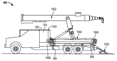
subject during filming, or to move the camera around a subject, move in, back-
up or
move diagonally in any direction, the motion base is pushed over the ground by
the
filming crew, or the motion base may be self-propelled via an on-board motor,
with or
without also using telescoping movement. Dramatic improvements in telescoping
camera crane arms have recently been achieved, for example as described in
U.S.
Patent No. 8,033,742. This type of camera crane arm can provide a reach of
over 70
feet (23 meters) with exceptional stability, all weather, and underwater
capability.
[0002] As filming often takes place on location outside of a studio,
camera cranes
are frequently transported by truck to the filming location. However, the
relatively larger
size and weight of modern camera cranes present special transport challenges.
BRIEF STATEMENT OF THE INVENTION
[0003] A camera crane carrier includes a vehicle having a front elevator
movable
vertically between up and down positions, at a forward position on a deck of
the vehicle.
A back elevator is movable vertically between up and down positions, at a
rearward
position, below the deck. A ramp may be provided on the vehicle, with the ramp
CA 02874064 2014-11-19
WO 2013/184420 PCT/US2013/042733
extendible from the deck at the back end of the vehicle to the ground. The
elevators
allow a camera crane to be more easily loaded onto the vehicle, and also allow
lowering
the center of gravity of the loaded vehicle. The vehicle may optionally be
used as a
camera car when not carrying a camera crane.
BRIEF DESCRIPTION OF THE DRAWINGS
[0004] In the drawings, the same reference number indicates the same
element
in each of the views.
[0005] Fig. 1 is a side view of a camera crane transport vehicle with a
tailgate
ramp deployed.
[0006] Fig. 2 is a side view of the camera crane transport vehicle of
Fig. 1 with
the tailgate ramp folded.
[0007] Fig. 3 is a plan view of the camera crane transport vehicle shown
in Fig. 1.
[0008] Fig. 4 is a rear view of the camera crane transport vehicle shown
in Fig. 1.
[0009] Figs. 5-9 are side views showing a sequence of operation of the
tailgate
ramp shown in Figs. 1 and 2.
[0010] Figs. 10-15 are side views showing a sequence of operation of the
camera
crane transport vehicle shown in Fig. 1.
[0011] Fig. 16 is a side view provided for comparison to Fig. 15.
[0012] Fig. 17 is an enlarged side view of the camera crane loading
sequence
occurring between the positions shown in Figs. 12 and 13.
[0013] Fig. 18 is an enlarged detail view of the rear elevator shown in
Fig. 17.
[0014] Fig. 19 is a side view of operation of the camera crane shown in
Fig. 16
while the camera crane is on the vehicle shown in Fig. 2.
-2-
CA 02874064 2014-11-19
WO 2013/184420 PCT/US2013/042733
DETAILED DESCRIPTION OF THE DRAWINGS
[0015] A camera crane typically includes a crane arm, for example as
described
in European Patent Application No. 1721213, mounted on a mobile base, for
example
as described in International Patent Publication WO 2012/015763. As camera
cranes
may weigh over 4500 kg and have a high center of gravity, loading and
transporting
camera cranes on conventional over-the-road trucks can be difficult. Fig. 1
shows an
improved vehicle for loading and transporting large camera cranes.
[0016] As shown in Fig. 1, a camera crane transport vehicle 40 has a cab
44 on a
front chassis 42. Since the vehicle 40 may also be used as a camera car, a cab
deck
46 may be provided on top of the cab 44, to allow camera crew to more securely
climb
or stand on top of the cab, without damaging the vehicle. A hood deck 48 may
similarly
be provided on the hood of the vehicle 40. Front platform fittings 50 may be
attached to
the chassis 42 to allow a front platform to be attached to the vehicle 40, for
camera car
operations. A standard truck, such as a Ford 550 truck or similar, may be used
to
provide the front section of the vehicle 40, including the cab 44, the engine,
steering and
front drive wheels 52, and the front chassis 42. The rear section of the
vehicle 40 may
be made with a reinforced rear chassis 60 to better handle loads beyond the
specifications of the standard truck. The rear chassis 60 is joined to the
front chassis
42 via welding or bolting. Of course, a single purpose-built chassis may also
be used.
[0017] In the design shown in Fig. 1, the vehicle 40 has two rear axles,
with dual
wheel pairs on each side, for a total of eight rear wheels 76, along with the
two front
wheels 52. All 10 wheels of the vehicle 40 may be linked to the vehicle drive
train, to
allow the vehicle to better move over soft or slippery ground, or handle steep
inclines,
-3-
CA 02874064 2014-11-19
WO 2013/184420 PCT/US2013/042733
as is often required to deliver the camera crane to the filming location. A
standard truck
may be modified for this purpose by adding a second rear axle.
[0018] In this design, the stock drive shaft 64 is connected to a front
transfer case
66, which drives a front axle set 74 through a front differential 72. The
front differential
drives the forward four wheels 76 on the front axle set 74. The front transfer
case also
drives a transfer shaft 68 that connects the front transfer case 66 to a rear
transfer case
70. The rear transfer case 70 drives the rear four wheels 76 on the second
rear axle set
82 via the rear differential 80. Stabilizer bars 78 may be used to reduce
twisting
movements of the drive line components. All of the axles may be attached to
the
chassis via air bags or air springs 92. For added stability, for example in
high winds, the
air springs 92 may be deflated sufficiently to allow the chassis to rest on
the axles via a
direct hard connection (e.g., metal-to-metal).
[0019] The rear axles may be positioned close together, for example with
a tire
clearance TT shown in Fig. 3 of less than 15, 13 or 11 cm. This reduces tire
scrubbing
as the vehicle turns. Under certain conditions, for example when moving over
soft
ground such as sand, the tires may be deflated for improved traction. However,
the
lower air pressure in the deflated tires reduces the friction forces holding
the tire onto
the rim. Under high torque/low tire pressure conditions, the wheel may slip
within the
tire. To prevent this occurrence, the tires may optionally be pinned or bolted
to the
wheels. For example, bolts may be placed through holes in thick sidewall areas
of the
tires, to lock the tire onto the wheel.
[0020] As shown in Figs. 1 and 3, the vehicle 40 includes a front
elevator 86 and
a rear elevator 88. The elevators 86 and 88 may each be provided as separate
left and
-4-
CA 02874064 2014-11-19
WO 2013/184420 PCT/US2013/042733
right lift devices, such as hydraulic cylinders. Alternatively, a single front
and a single
rear elevator may raise and lower a single lateral plate extending across the
vehicle 40.
A deck 90 is supported on top of the chassis 60. The deck 90 includes
laterally spaced
apart rollways 96 generally matching the lateral wheelbase of the camera crane
160, as
shown in Fig. 3. The rollways 96 are flat structural surfaces that can support
the weight
of the camera crane 160 as it is loaded onto the vehicle 40. The areas 98 of
the deck 90
between the rollways 96 may be at the same level as the rollways 96. In this
case, the
deck 90 provides a generally flat open platform to allow use of the vehicle 40
as a
camera car when the vehicle 40 is not carrying a camera crane. Various types
of
fittings and receptacles may be provided on the deck 90 to allow installation
of camera
car accessories, such as support or safety bars, frames, gates, and
extensions.
[0021] Figs. 5-9 show operation of the tailgate ramp 100 show in Fig. 1.
The
terms front and back refer to the tailgate ramp 100 in the unfolded or
deployed position
shown in Fig. 5. Figs. 5-9 show the left side of the vehicle 40, with
corresponding
elements generally on the right side as well, so that the vehicle and
components
described may be provided in a substantially symmetrical arrangement.
Referring to
Fig. 5, the tailgate ramp 100 may include a ground plate 108 on a triangle
frame 110.
The triangle frame 110 may be pivotally attached to the back end of a link
plate 112 at a
link pivot joint 118. The front end of the link plate 112 may be pivotally
attached to a
rear sub-deck 102 via a gate pivot joint 120. The sub-deck 102 is vertically
below the
level of the deck 90. Caster wheels 122 may be provided at the front end of
the ground
plate 108, to allow the triangle frame 110 to roll on the ground GG during
fold/unfold
-5-
CA 02874064 2014-11-19
WO 2013/184420 PCT/US2013/042733
operation of the tailgate ramp 100. Tail lights 114 along with brake lights
and/or other
vehicle components may be attached to the front end of the triangle frame 110.
[0022] From the deployed position shown in Fig. 5, the tailgate ramp 100
is
moved into a folded position as shown in Fig. 9 as follows. A tailgate cable
106 on a
tailgate winch 104 is attached to a cable anchor 124 of the ground plate 108
or other
position on the triangle frame 110. The tailgate winch 104 may be operated
manually
via a handle crank 105, or it may be electrically or hydraulically powered.
However, as
the tailgate ramp folding/unfolding operation is performed with no load on the
tailgate
ramp 100, a powered winch generally should not be needed.
[0023] Turning to Fig. 6, the tailgate winch 104 pulls on the cable 106
causing the
back end of the ground plate 108 to lift off of the ground with the triangle
frame 110
rotating counterclockwise. As shown in Figs. 6 and 7, the caster wheels 122
roll on the
ground as the ground plate 108 continues to rotate through an upright
position. Pulleys
116 may be used to position the winch cables on each side of the tailgate ramp
100.
Referring to Fig. 9, as the winch 104 continues to draw the cables 106 in, the
triangle
frame 110 pivots about link pivot joint 118 and lifts up and off of the ground
GG. At the
same time the link plate 112 pivots about the gate pivot joint 120.
[0024] Fig. 9 shows the tailgate ramp 100 in the completely folded
position. The
back end of the ground plate 108 rests on stops, with the now up-facing bottom
surface
of the ground plate 108 generally flush with the deck 90. The folded tailgate
ramp 100
can then act as an extension of the deck 90 when the vehicle 40 is used as a
camera
car. As shown in Fig. 9, with the tailgate ramp 100 fully folded, the
taillights 114 face
the rear.
-6-
CA 02874064 2014-11-19
WO 2013/184420 PCT/US2013/042733
[0025] The vehicle 40 may optionally be provided without any tailgate
ramp 100.
In this case, a separate ramp may be used instead of the tailgate ramp 100, in
the
loading sequence to the sub-deck 102 as described below, or by rolling the
camera
crane directly up onto the deck. It may also be possible to load a camera
crane onto
the vehicle using a fork lift, construction crane, or other lifting equipment,
without the
use of any ramp.
[0026] Figs. 10-15 illustrate loading a camera crane 160 onto the
transport
vehicle 40. In Fig. 10, the camera crane 160 includes a telescoping arm 162
having a
21 meter reach, with about 18 meters of telescoping travel. The arm 162 weighs
about
1800 kg excluding accessories. The arm is supported on the mobile base 164 at
a
position typically at least 3 meters above the ground GG. The mobile base 164
typically
weighs about 2200 kg. The center of gravity of the combination of the crane
arm 162
and the mobile base 164, which together form the camera crane 160, accordingly
may
be close to 1.4 meters above the ground. Of course, the transport vehicle 40
can be
used to transport various other types of camera cranes as well.
[0027] Referring to Fig. 10, with the tailgate ramp 100 deployed, a crane
cable
142 attached to a crane winch 140 is attached to the camera crane 160. The
tailgate
ramp 100 extends up from the ground GG to the sub-deck 102, which is below (at
a
lower height above the ground) than the deck 90. The winch 140 pulls the
camera
crane 160 up the tailgate ramp 100, until the front wheels 166 of the mobile
base 164
are positioned on the back elevator 88, as shown in Fig. 11. In the design
shown, the
back elevator 88 is provided as two a pair of hydraulic actuators aligned
under the
rollways 96. As shown in Fig. 17, a top plate 170 may be attached onto the
upper end
-7-
CA 02874064 2014-11-19
WO 2013/184420 PCT/US2013/042733
of each actuator, to provide a support surface for the wheels of the mobile
base 164.
The front elevators 86 may have the same design.
[0028] With the front wheels 166 on the rear elevators 88, the winch 140
is
stopped. The rear elevators 88 are then actuated to lift the front wheels 88
up to the
level of the deck 90, as shown in Fig. 12. The winch 140 is then used to
further pull the
camera crane 160 onto the deck 90. The rear elevators 88 are lowered back down
to
the original position on the sub-deck 102. This may be achieved by using
actuators
which exert force in both the up and down directions.
[0029] However, a single action actuator may also be used, with the down
movement of the rear elevators achieved using the weight of the camera crane.
Referring momentarily to Figs. 17 and 18, a roller 174 may be provided on each
end of
the retraction bar 172 (shown in Fig. 4) extending laterally across the sub-
deck 180 and
connecting the two rear elevators 88. As the mobile base 164 moves over the
rear
elevators, bottom surfaces 180 of the mobile base contact the rollers 174 and
act to
push the rollers and retraction bar 172 down, returning the rear elevators
back to the
down position shown in Fig. 15, if used, are laterally and vertically
positioned so that the
bottom surface 180 of the mobile base 164 The winch 140 continues pulling the
camera
crane 160 onto the vehicle 40 until the front wheels 166 are positioned on top
of the
front elevators 86, which are in the up position, as shown in Fig. 13. The
winch 140 and
the elevators 86 and 88 may be controlled via a control panel 84 near the back
end of
the vehicle 40. In an alternative design, the winch 140 may be omitted and the
camera
crane 160 moved onto the vehicle 40 using the drive system of the camera
crane.
-8-
CA 02874064 2014-11-19
WO 2013/184420 PCT/US2013/042733
[0030] The front and rear elevators are spaced apart in the front-to-back
direction
of the vehicle by the same dimension as the front-to-back wheelbase of the
mobile base
164. Consequently, with the front wheels 166 on the front elevators 86, the
back
wheels 168 of the camera crane are positioned on top of the rear elevators 88.
As
shown in Fig. 13, the camera crane 160 at this position is at an inclined
angle, because
the front wheels 166 are at the level of the deck 90 or the rollways 96, while
the back
wheels 168 are at the level of the sub-deck 102, approximately 20-60 cm or 25-
46 cm
below the deck 90.
[0031] The front elevators 86 are then lowered, moving the crane from the
interim
loading position shown in Fig. 13 to the final transport position shown in
Fig. 14. As this
lowering movement occurs, the bottom surface of the chassis of the mobile base
164
comes to rest on below deck support surfaces or hard points 94 on the vehicle
40. The
wheels 166 and 168 of the mobile base 164 move into open recesses below the
deck
90 and are unloaded, i.e., no longer carrying the weight of the camera crane
160.
Consequently, the camera crane 160 may be rigidly supported on the vehicle 40.
Clamping devices may be used to lock the camera crane 160 in place in the
position
shown in Fig. 14. The tailgate ramp 100 is folded up, as shown in Fig. 15.
[0032] The vehicle 40 is then ready to transport the camera crane 160 via
over-
the-road or off-road routes. At the filming destination, the reverse sequence
is followed
to unload the camera crane 160, except that the mobile base 164 may be moved
manually, or via its own drive and braking systems. The winch 140 may then
optionally
be used to slowly lower the camera crane down the tailgate ramp 100. Since the
crane
arm 162 is already installed on the mobile base 164, the camera crane 160 may
be
-9-
CA 02874064 2014-11-19
WO 2013/184420 PCT/US2013/042733
used without delay. In addition, the crane arm 162 may be balanced in advance
by
adding or removing static counterweights, based on the payload (i.e., the
camera,
camera accessories, and crane accessories, such as a remote control and/or
gyro
stabilized camera head, to be used in the filming sequence). This saves time
and
reduces the complexity of getting the camera crane 160 set up and ready for
use at the
filming location. It also allows the camera crane 160 to be set up and
balanced
beforehand, in an indoor location under controlled conditions.
[0033] Fig. 16 shows the position of the camera crane 160 as it would be
if
loaded onto a convention flat bed truck, with the wheels 166 and 168 on the
deck of the
truck. In comparison, Fig. 15 shows the position of the camera crane 160 as
loaded
onto the vehicle 40. As shown, with the vehicle 40, the camera crane 160 is
about
approximately 20-60 cm or 30-45 cm below the position shown in Fig. 16.
Consequently the center of gravity of the camera crane 160, i.e., the load on
the vehicle
40, is correspondingly lowered. The loaded vehicle 40 is therefore more
stable. In
addition, since the camera crane 160 is supported on the structural support
surfaces 94
of the vehicle 40, and not via its own wheels and suspension, the load does
not shift as
the vehicle makes turns or traverses uneven ground.
[0034] The vehicle 40 as shown in Fig. 2 may be used as a conventional
camera
car. Any openings in the deck 90 may be covered with hinged, sliding or
removable
plates, to provide a generally uninterrupted flat deck surface.
[0035] For some applications, the camera crane 160 may also be used while
it is
on the vehicle 40, as shown in Figs. 16 and 19. To allow for a full range of
motion of the
crane arm 162 while the crane 160 is on the vehicle 40, the vehicle may be
lengthened
-10-
CA 02874064 2014-11-19
WO 2013/184420 PCT/US2013/042733
so that the back section 184 of the crane arm clears the cab 44 and any other
equipment on the vehicle, such as the generator 54 and the generator cover or
deck 56
shown in Fig. 16. Alternatively, the generator 54 and the generator deck 56
may be
removed to provide greater clearance. Raising the vertical position of the
crane arm
162 also adds clearance. The crane arm may be raised by moving the front and
rear
elevators to the up position, as shown in Fig. 16.
[0036] If the camera crane 160 has a height-adjustable center column 182,
the
center column may be used to further raise the crane arm 162, as shown in Fig.
19.
The length of the back section 184 of the crane arm 162 (from the pivot
attachment on
the center column to the back end of the crane arm) may also optionally be
made
shorter by shifting the location of the pivot attachment. Although more
counter weights
will be needed to balance the crane arm 162 in this configuration, shortening
the back
section 184 can help to allow for a full range of movement, as shown in Fig.
19. The
added weight of the additional counter weights may be partially or even fully
offset
however by removing the generator 54 from the vehicle 40. Hold down straps or
bars
may used to securely lock the camera crane 160 down onto the vehicle 40.
[0037] Referring still to Fig. 19, the camera crane 160 may be used while
on the
vehicle 40, to support a camera during filming, where the filming sequence
requires
movement of the camera over rough or uneven ground. The camera crane 160 can
also be moved off of the vehicle 40 and used independently of the vehicle 40.
If the
mobile base 164 of the camera crane 160 is electrically powered, the camera
crane 160
can be used indoors, or in other locations inaccessible or otherwise barred to
the
vehicle 40. With conventional camera cranes, switching from outdoor to indoor
use
-11-
CA 02874064 2014-11-19
WO 2013/184420 PCT/US2013/042733
typically requires moving the crane arm 162 from an outdoor mobile base or
vehicle
(such as an over the road truck) to an indoor mobile base (such as an electric
stage
crane base). This is a time consuming operation. It also requires using a fork
lift truck
or construction crane. The combination of the camera crane 160 and the vehicle
40 as
described above allows for both outdoor and indoor use, without the need to
switch the
crane arm 162 between mobile bases.
-12-