Note: Descriptions are shown in the official language in which they were submitted.
CA 0287.1537 2014-11-24
END PLATE FOR AN ELECTRIC MACHINE, ELECTRIC MACHINE AND
METHOD FOR ASSEMBLING AN ELECTRIC MACHINE
The invention relates to an end plate for an electric
machine, an electric machine equipped with such an end
plate and a method for assembling the electric machine.
From DE 10 2009 001 948 Al an end plate for an electric
machine is known, which comprises an inner ring as a
bearing receptacle, in which a bearing equipped for
rotatably mounting a rotor of the electric machine can be
accommodated, and an outer ring as a radially outwardly
pointing outer circumferential contour, which for radially
supporting the end plate can be fitted under preload into
an inner circumference of a stator housing of the electric
machine.
From DE 10 2009 019 593 Al is evident an electric machine
with a stator comprising a stator housing, a rotor arranged
in an inner circumference of the stator housing and an end
plate, in which a bearing for rotatably mounting the rotor
is accommodated in a bearing receptacle. On the end plate,
an active magnetic bearing is provided, by way of which in
the case of an energised magnetic bearing a rotor shaft of
the rotor is rotatably mounted radially. A catch bearing
of the active magnetic bearing comprises an inner ring
which encloses the rotor shaft and which has an inner
diameter that is greater by a predetermined dimension than
an outer diameter of the rotor shaft, so that in the case
of an energised magnetic bearing an annular gap between
rotor shaft and inner ring is formed and in the case of
non-energised magnetic bearing the rotor shaft rests on the
inner ring on the inside.
The winding of an electric machine, such as of an electric
motor, naturally generates forces which ideally are
substantially converted completely into a rotational moment
CA 02874537 2016-04-15
- 2 -
on the rotor that can be completely utilised at an output
(e.g. a coupling) of the electric machine. In reality,
however interference forces also act on the rotor which can
impair the optimal rotation of the same. These
interference forces can be created when individual phase
windings have slightly different electric characteristics,
the lamination has local variations and/or the rotor does
not rotate precisely concentrically in the stator. The
latter can become manifest in that periodical force
excitations act on the rotor with a multiple of the
electric frequency. In the
specialist literature, this
phenomenon is known as "unbalanced magnetic pull" (UPM).
Investigations regarding this phenomenon are published for
example in "EFFECTS OF CONSTANT UNBALANCED MAGNETIC PULL TO
THE VIBRATION BEHAVIOURS OF TURBO MACHINERY", Zhemin Cai
and Ningsheng Feng, ICSV15, 15th International Congress on
Sound and Vibration, 6-10 July 28, Daejeom, Korea and in
"SIMULATION OF THE EFFECTS OF THE UNBALANCED MAGNETIC PULL
IN 4-POLE SLIM GENERATORS", P. Pennacchi and L. Frosini.
The abovementioned phenomenon causes undesirable vibrations
in the rotor shaft (rotor dynamics) and thus potentially
throughout the electric machine. This can
constitute a
serious problem in the case of high-frequency motors with
small air gaps in the electric machine.
The invention is based on the object of providing an end
plate for an electric machine, an electric machine and a
method for assembling an electric machine, so that
undesirable eccentricities of the rotor and thus vibrations
can be avoided.
This is achieved according to a first aspect of the
invention with an end plate for an electric machine,
comprising a magnetic bearing configured to rotatably mount
a rotor of the electric machine; a bearing receptacle,
CA 02874537 2016-04-15
- 2A -
configured to accommodate the magnetic bearing therewithin;
and a radially outer circumferential contour, on which at
least three support elements are provided, each of which
protrudes radially to the outside, with respect to the
circumferential contour, by a protruding amount so as to
define a discontinuous outer circumferential contour of the
end plate; wherein the respective protruding amounts of the
at least three support elements are dimensioned so that the
end plate is fitted in by making a center of the magnetic
bearing coincide with at least one of a geometrical
longitudinal axis of the electric machine and a magnetic
longitudinal axis of the electric machine.
This is also achieved according to the first aspect of the
invention with an electric machine comprising a stator
having a stator housing; a rotor arranged in an inner
circumference of the stator housing; and the aforementioned
end plate; wherein for rotatably mounting the rotor, the
magnetic bearing is received in the bearing receptacle of
the end plate, and for radially supporting the end plate
the outer circumferential contour is fitted into the inner
circumference of the stator housing such that the center of
the magnetic bearing is fitted in with at least one of a
geometrical longitudinal axis of the electric machine and a
magnetic longitudinal axis of the electric machine.
This is also achieved according to the first aspect of the
invention with a method for assembling the aforementioned
electric machine, the method comprising: inserting the
rotor in the stator housing; fitting the outer
circumferential contour of the end place into the inner
circumference of the stator housing, so that the magnetic
bearing and the inner ring of the catch bearing enclose the
rotor shaft; and operating the electric machine so that its
rotor with an energized bearing rotates;
CA 02874537 2016-04-15
- 28 -
determining a vibration behavior of the rotor; determining
a correction offset from the vibration of the motor; and
changing the respective protruding amounts of the support
elements based on the correction offset.
CA 0287.1537 2014-11-24
- 3 -
A realisation of the invention is that in order to avoid
UP-based vibrations of the rotor one should endeavour to
arrange the rotor as concentrically as possible relative to
the stator. The concentricity with respect to the magnetic
central axis or longitudinal access of the electric machine
and/or the geometrical central axis or longitudinal axis of
the electric machine is decisive. The magnetic
longitudinal axis and the geometrical longitudinal axis can
coincide but not necessarily so.
Since production and assembly tolerances have to be always
expected, it cannot be prevented in reality that the centre
of a magnetic bearing mounting the rotor accommodated in
the end plate does not exactly coincide with the magnetic
longitudinal axis of a stator winding of the stator. Since
this magnetic longitudinal axis of the stator winding in
first approximation substantially coincides with a
longitudinal centre axis of an inner circumference or inner
diameter of a stator housing of the electric machine and
thus the geometrical longitudinal axis of the electric
machine it is thus advantageous to primarily align the
centre of the magnetic bearing according to the inner
circumference of the stator housing or the geometrical
longitudinal axis of the electric machine. However, this
alignment is ideally made with respect to the magnetic
longitudinal axis of the electric machine.
According to the invention, the end plate for the electric
machine, such as in particular an electric motor or an
electric generator, therefore comprises at least the
following elements. A bearing
receptacle, in which a
magnetic bearing equipped for rotatably mounting a rotor of
the electric machine, which is preferably designed as an
active magnetic bearing with associated catch bearing can
be accommodated; a radially outwardly pointing
circumferential contour, on which a number of at least
CA 0287.1537 2014-11-24
- 4 -
three support elements - also called shimming pads - is
provided, each of which protrude radially beyond the
circumferential contour by a predetermined protruding
amount so that said support elements define a discontinuous
outer circumferential contour of the end plate; wherein the
respective protruding amounts of the support elements are
dimensioned so that the end plate can be fitted in by
making a centre of the magnetic bearing coincide with a
geometrical longitudinal axis of the electric machine
and/or a magnetic longitudinal axis of the electric
machine.
By specifically influencing or adjusting the respective
protruding amounts production and assembly tolerances can
be offset. Because of the fact that following the fitting-
in of the outer circumferential contour the centre of the
magnetic bearing coincides with the geometrical
longitudinal axis and/or magnetic longitudinal axis of the
stator of the electric machine, the rotor is consequently
arranged optimally concentrically to the stator housing, as
a result of which periodic force excitations and
concomitant undesirable vibrations of the rotor can be
largely reduced or avoided.
According to a preferred embodiment of the end plate
according to the invention, the support elements are each
mounted radially adjustably on the circumferential contour
so that the respective protruding amounts of the support
elements can be changed, i.e. can be specifically
influenced or adjusted time and again. Such a radial
adjustment can for example be realised with a thread-
controlled self-locking and/or separately lockable sliding
guide or with exchangeable shims.
According to a further preferred embodiment of the end
plate according to the invention, each support element has
a contact body located radially outside for contacting the
CA 0287.1537 2014-11-24
- 5 -
inner circumference of the stator housing and an individual
number of shims radially shimmed under towards the inside,
wherein each shim has a certain radial thickness dimension.
A shim or multiple shims of the same or different radial
thickness dimension can be placed under the contact body.
This configuration of the invention is particularly robust
and can be easily and cost-effectively realised.
According to yet another preferred embodiment of the end
plate according to the invention, the support elements are
arranged in respective recesses, which in each case extend
from the circumferential contour radially to the inside and
circumferentially of the end plate. In the recesses,
fastening means - for example the screw heads of screws -
can be advantageously accommodated so that these do not
take up any additional space radially.
According to yet a further embodiment of the end plate
according to the invention, the support elements are
arranged in two groups of support elements distributed
about the circumferential contour, wherein the support
elements of a first group of these two groups are in
engagement with the inner circumference of the stator
housing in order to fit in the end plate relative to the
stator housing, and wherein the support elements of a
second group of these two groups are in engagement with the
inner circumference of a connecting housing in order to fit
in the connecting housing with respect to the stator
housing independently of the end plate. Preferentially,
the support elements for this purpose each have a support
surface located radially outside which is formed stepped
axially to the end plate, wherein the stepping of a first
group with at least three support elements radially rises
in a first axial direction as far as to the respective
protruding amount and the steps of a second group with at
least three support elements radially rises as far as to
the respective protruding amount in a second axial
CA 02874537 2016-04-15
- 6 -
direction, and wherein within each of the two groups the
support elements are arranged with a defined angular
spacing from one another preferentially symmetrically about
the circumferential contour. This
configuration is
advantageous for electric machines in which a connecting
housing is flanged to the stator housing.
Through the opposite stepping of the two groups the support
surfaces of one of the two groups, preferably upon the
assembly of the end plate, first come into contact with the
inner circumference of the stator housing so that any
adjustment of the protruding amounts of this group can be
carried out if necessary. Through the opposite stepping,
the support surfaces of the other one of the two groups
only come into contact with the inner circumference of the
connecting housing during the further assembly of the
connecting housing. Since the
protruding amounts of the
first group are matched, the same provides the desired
centring of the end plate so that the protruding amounts of
the second group can be utilised for centring the
connecting housing independently of the centring of the end
plate.
According to the first aspect of the invention, the
aforementioned electric machine is additionally provided,
as in particular an electric machine embodied as electric
motor or as electric generator, which comprises a stator
comprising a stator housing, a rotor arranged in an inner
circumference of the stator housing and the aforementioned
end plate according to the first aspect of the invention.
Details of the end plate according to the first aspect of
the invention are described above.
According to an embodiment of the electric machine
according to the invention, the rotor is radially mounted
by way of magnetic bearings arranged on both sides of the
electric machine, which in each case are incorporated in
CA 0287.1537 2014-11-24
- 7 -
the electric machine via an end plate according to the
invention.
The magnetic bearings can be passive magnetic bearings and
active magnetic bearings.
In the event of a failure of a magnetic bearing system with
active magnetic bearings, catch bearings are provided which
catch the rotor.
Magnetic bearings and catch bearings of such active
magnetic bearings are generally available as a preassembled
unit.
Preferentially roller bearings are employed as catch
bearings. However, sliding bearings can also be employed
as catch bearings.
If embodied as roller bearings, the catch bearings should
not co-rotate during normal operation. For this reason,
there is an air gap of a few tenth of a millimetre between
the inner ring of said catch bearings and the fast-rotating
rotor. This air gap is the closest gap of the entire rotor
shaft since in the case of a rotor crash falling off the
rotor into structures other than the catch bearings is to
be prevented. For this reason, the magnetic bearings hold
the rotor in the centre of these catch bearings during
normal operation.
According to a preferred embodiment of the electric machine
according to the invention, an active magnetic bearing is
provided on the end plate, via which on energising the
magnetic bearing a rotor shaft of the rotor is rotatably
mounted radially, wherein the catch bearing of the active
magnetic bearing has an inner ring which encloses the rotor
shaft and which has an inner diameter that is greater by a
predetermined dimension than an outer diameter of the rotor
CA 0287.1537 2014-11-24
- 8 -
shaft, so that with energised magnetic bearing an annular
gap is formed between rotor shaft and inner ring of the
catch bearing and with non-energised magnetic bearing the
rotor shaft rests on the inner ring of the catch bearing
inside.
According to a further preferred embodiment of the electric
machine according to the invention, the same additionally
comprises a control device for electrically activating the
active magnetic bearing so that with energised magnetic
bearing an axis of rotation of the rotor shaft coincides
with the centre of the magnetic bearing.
Since, as explained above, production and assembly
tolerances always have to be expected, it cannot be
prevented in reality that the centre of the magnetic
bearings and in the case of active magnetic bearings with a
preassembled unit of magnetic bearing and catch bearing,
the catch bearings do not exactly coincide with the
magnetic central axis or longitudinal axis of the stator
winding either. An offset (axes not aligned) however, as
explained above, results in the undesirable phenomenon of
forces periodically acting on the rotor caused by UPM.
Remedy is provided by the radially adjustable end plate
according to the invention, wherein the adjustment is
preferably realised during the assembly process through
precise measuring. The centre of the magnetic bearing and
in the case of active magnetic bearings also the catch
bearing in this case is adjusted with the centre of the
stator winding, which in first approximation is performed
via the alignment according to the inner circumference or
inner diameter of the stator housing or the geometrical
longitudinal axis of the stator, preferentially according
to the magnetic longitudinal axis of the stator.
According to the invention, a method for assembling the
electric machine according to the invention is additionally
CA 0287.1537 2014-11-24
- 9 -
provided, wherein the method comprises the steps: inserting
the rotor in the stator housing; fitting the outer
circumferential contour of the end plate into the inner
circumference of the stator housing, so that the magnetic
bearing and the inner ring of the radial bearing each
enclose the rotor shaft; operating the electric machine so
that its rotor with energised magnetic bearing rotates;
determining a vibration behaviour of the rotor, determining
a correction offset from the vibration behaviour, changing
the respective protruding amounts of the support elements
based on the correction offset. Changing the
respective
protruding amounts in this case is effected in such a
manner that the vibration behaviour of the electric machine
is optimised. This is effected
by making the axis of
rotation of the rotor shaft of the electric machine and the
geometrical longitudinal axis and/or the magnetic
longitudinal axis of the stator of the electric machine
coincide.
Through the method according to the invention the
possibility is utilised in particular of realising fine
adjustments of the rotor with respect to the magnetic
central axis or longitudinal axis of the stator winding
based on an achieved operating behaviour or vibration
behaviour, by way of which electrical asymmetries can be
corrected. Determining the correction offset of the axis
of rotation of the rotor shaft with respect to the central
axis of the stator winding of the spacer and the
corresponding changing of the respective protruding amounts
of the support elements is effected either by way of tests
or multiple assembly and measurement iterations or by
calculation based on achieved operating behaviour.
The invention expressly extends also to such embodiments as
are not provided by feature combinations from explicit
references to the claims, so that the disclosed features of
CA 2874537 2017-04-13
the invention - as far as technically practical - can be
combined with one another as required.
An electric machine according to the invention according to
a second aspect of the invention is defined herein.
Accordingly, the support elements or shimming pads are not
accommodated in the end plate but in the stator housing
and/or in the connecting housing and contact the end plate.
In the following, the invention is described in more detail
with the help of a preferred embodiment and making
reference to the attached figures.
Fig. 1 shows a perspective view of a stator of an
electric machine according to an embodiment of
the invention according to the first aspect of
the invention.
Fig. 2 shows a perspective exploded view of the electric
machine of Fig. 1.
Fig. 3 shows a perspective view of an end plate of the
electric machine of Fig. 1.
Fig. 4 shows a view in axial direction of the end plate
of Fig. 3.
Fig. 5A shows a perspective view of a support element of
the end plate of Fig. 3 belonging to a group.
Fig. 53 shows a sectional view of a part of the end plate
viewed along a line A-A in Fig. 4.
Fig. 6A shows a perspective view of a support element of
the end plate of Fig. 3 belonging to a further
group.
CA 2874537 2017-04-13
- 11 -
Fig. GB shows a
sectional view of a part of the end plate
viewed along a line B-B in Fig. 4.
Fig. 7 shows an enlarged view of a region C of Fig. 4.
Figs. 8A-8B show
alternatives to the support elements of
Fig. 5 and 6.
Figs. 9A-913
schematically show details of cross sections
of an electric machine according to the
second aspect of the invention.
Fig. 1 and 2 show an electric machine 1 according to an
embodiment of the invention. The electric
machine 1 is
preferably formed as an electric motor or as an electric
generator.
The electric machine 1 is provided with a stator 10
comprising a stator housing 11 and a stator laminated core
14, a rotor 20 arranged in an inner circumference 12 of the
stator housing 11 with a rotor shaft 21 and on each of two
ends in an axial direction AR of the electric machine 1 an
end plate 30 each, wherein in Fig. 2 only one end plate 30
is visible.
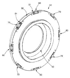
As is additionally evident from the Figures 3 to 7, each
end plate 30 comprises a bearing receptacle 40 and a
circumferential contour 50 radially pointing outwards.
In the bearing receptacle 40 of the end plate 30 a bearing
in the form of a magnetic bearing 80 equipped for rotatably
mounting the rotor 20 :is accommodated. The magnetic
bearing 80 can be a passive magnetic bearing or an active
magnetic bearing.
Preferentially, an active magnetic
bearing 80 is employed.
CA 0287.1537 2014-11-24
- 12 -
Fig. 10 shows a schematic cross section through an electric
machine 1 in the region of an active magnetic bearing 80.
In addition to the active part 81 of the magnetic bearing
80 on the stator side, which interacts with a laminated
core 84 of the magnetic bearing 80 on the rotor side, the
active magnetic bearing 80 comprises a catch bearing 82 on
the stator side in order to be able to catch the rotor 20
in the event of a failure of the magnetic bearing. The
catch bearing 82 can be designed as a roller bearing or
sliding bearing.
The reference number 83 marks a gap in the region of the
catch bearing 82, which defines the smallest radial play of
the magnetic bearing 80.
The active magnetic bearing 80 is electrically activated by
a preferably electronic control device 90.
On the circumferential contour 50, a number of at least
three - in the shown embodiment two groups of four support
elements 60, 70 each - are provided, each of which radially
protrudes over the circumferential contour 50 by a certain
protruding amount M (see Fig. 7), so that they define a
discontinuous outer circumferential contour of the end
plate 30. As is evident from Fig. 4, the support elements
60, 70 in the shown embodiment are arranged symmetrically
to one another by a respective angular spacing of 45
degrees distributed about the circumferential contour SO.
The respective protruding amounts M of the support elements
60, 70 are dimensioned so that the outer circumferential
contour formed by these can be fitted in or is fitted in
for radially supporting the end plate 30 by making a centre
of the magnetic bearing 80 coincide with a geometrical
longitudinal axis A2 of the stator 10 of the electric
machine 1 and/or of a magnetic longitudinal axis A4 of the
stator 10 of the electric machine 1.
CA 2874537 2017-04-13
- 13 -
The catch bearing of an active magnetic bearing 80
comprises an inner ring, which encloses the rotor shaft 21
and which has an inner diameter that is greater by a
predetermined dimension than an outer diameter of the rotor
shaft 21, so that with energised magnetic bearing 80 the
annular gap 83 between Totor shaft 21 and inner ring is
formed and with nonmenerg_sed magnetic bearing 80 the rotor
shaft 21 rests on the inner ring on the inside.
The control device 90 activates an active magnetic bearing
80 so that with energised magnetic bearing 80 an axis of
rotation A3 of the rotor shaft 21 is made to coincide with
the axis of rotation of the magnetic bearing and indirectly
of the catch bearing.
The support elements 60, 70 are each radially adjustably
mounted to the circumferential contour 50, so that the
respective protruding amounts M of the support elements GO,
70 can be changed to make the centre of the magnetic
bearing 80 coincide with the geometrical longitudinal axis
A2 and/or the magnetic lcngitudinal axis A4 of the stator
of the electric machinc 1.
As is evident from Figs. 5A-5B and Figs. 6A-6B, each
support element 60, 70 ifor realising the adjustability,
comprises a contact body 61, 71 located radially outside
for contacting the inner circumference 12 of the stator
housing 11 and an individual number of shims 62, 72 shimmed
under the contact body 51, 71 radially to the inside,
wherein contact body 61, 71 and shims 62, 72 are detachably
fastened to the end plate 30 by means of screws 63, 73.
The support elements 60, 70, are arranged in respective
recesses 51 in the end pl,Lte 30, each of which extend from
the circumferential contour 50 radially to the inside and
circumferentially of the end plate 30, so that the screw
CA 0287.1537 2014-11-24
- 14 -
heads of the screws 63, 73 do not protrude radially over
the circumferential contour 50.
Each shim 62, 72 has a certain thickness dimension in a
radial direction RR. In the shown embodiment of the
invention, for example four shims 62, 72 with a radial
thickness dimension of 0.15 mm and seven shims 62, 72 with
a radial thickness dimension of 0.20 mm as nominal assembly
are stacked onto one another into a stack with a radial
overall thickness dimension GD of 2 mm.
Accordingly, the protruding amounts M which at the start of
the adjusting process are still identical according to an
embodiment of the invention in each case amount to for
example 4 mm.
For changing the respective protruding amounts M (e.g.,
analogously to the above exemplary dimensions in a range
from 2 mm to 6 mm) of the support elements 60, 70 so that
with assembled end plate 30 the centre of the magnetic
bearing 80 coincides with the geometrical longitudinal axis
A2 and/or the magnetic longitudinal axis A4 of the stator
of the electric machine 1, simply one or multiple shims
62, 72 have to be removed or added in one or multiple
adjusting steps corresponding to recorded measurement
values. Accordingly, an
envelope circle surrounding the
support elements 60, 70 is geometrically shifted relative
to the axis of rotation or the centre of the magnetic
bearing 80 accommodated in the end plate 30, so that with
the end plate 30 inserted in the stator housing 11 the axis
of rotation of the magnetic bearing 80 and thus the centre
of the magnetic bearing 80 is shifted relative to the
geometrical longitudinal axis A2 and/or to the magnetic
longitudinal axis A4 of the stator 10 of the electric
machine 1 to attain coincidence.
CA 2874537 2017-04-13
- 15 -
The support elements 60, 70 are arranged in two groups of
support elements distributed about the circumferential
contour 50. The support elements of a first group of these
two groups are in engagement with the inner circumference
12 of the stator housing 11, in order to fit in the end
plate 30 with respect to the stator housing 11. The
support elements of a second group of these two groups are
in engagement with the inner circumference 101 of a
connecting housing 100 in order to fit in the connecting
housing 100 with respect to the stator housing 11
independently of the end plate 30.
The connecting housing 100 can be a connecting housing of
the electric machine 1 or a stator housing of a further
machine.
Accordingly, the longitudinal axis of the connecting
housing 100 can be aligned with respect to the longitudinal
axis of the stator 10 of the electric machine 1, without
the coincidence of the centre of the magnetic bearing 80
with the geometrical longitudinal axis A2 of the stator 10
of the electric machine 1 and/or of the magnetic
longitudinal axis A4 of the stator 10 of the electric
machine 1 having to be changed.
Assuming that in Figs. 5A-5B and 6A-63 the stator housing
11 of the electric machine 1 is positioned on the right and
the connecting housing 101 on the left of the separating
plane 102 between stator housing 11 and connecting housing
101, the support elements 70 serve for aligning the end
plate 30 relative to the stator housing 11 and the support
elements 60 for the independent alignment of the inner
circumference of the connecting housing 101 relative to the
stator housing 11.
The support elements 60, 70 each comprise a support surface
61a, 71a located radially on the outside, which are formed
CA 0287.1537 2014-11-24
- 16 -
stepped axially with respect to the end plate 30, wherein
the stepping of the first group with at least three support
elements 60 radially rises in a first axial direction AR1
as far as to the respective protruding amount M and the
stepping of the second group with at least three support
elements 70 radially rises in a second axial direction AR2
as far as to the respective protruding amount M, and
wherein within each of the two groups the support elements
60, 70 are arranged with a defined angular spacing from one
another distributed about the circumferential contour 50.
In each of the two groups, the support elements 60, 70 are
preferentially arranged distributed symmetrically about the
circumferential contour 50 of the end plate 30.
In the shown exemplary embodiment, each of the two groups
comprises four support elements 60, 70 each, wherein within
each of the two groups of four the support elements 60, 70
are arranged with a respective angular spacing of 90
degrees relative to one another symmetrically distributed
about the circumferential contour 50.
Method steps according to the invention for assembling the
electric machine 1 are described in the following.
Initially, in a first method according to the invention,
the centre or the axis of rotation Al of each magnetic
bearing and thus also the centre of each magnetic bearing
80 is adjusted or made to coincide in a first approximation
via the alignment according to the inner circumference or
inner diameter 12 of the stator housing 11 with the
magnetic central axis A4 of a stator winding 13 of the
stator 10.
According to an embodiment of the invention, this is
realised with the following method steps to be carried out
one after the other:
CA 02874537 2014-11-24
- 17 -
Determining the position of the geometrical longitudinal
axis A2 of the inner circumference 12 of the stator housing
11 by measuring (e.g. by means of a 3D coordinate
measurement machine) the inner circumference 12 of the
stator housing 11. Fitting the
outer circumferential
contour of the end plate 30 into the inner circumference 12
of the stator housing 11 in the sense of rough adjustment.
In this regard: determining the position of the centre of
the magnetic bearing 80 relative to the position of the
geometrical longitudinal axis A2 of the inner circumference
12 of the stator housing 11 by measuring the bearing
receptacle 40 of the end plate 30. Subsequent determining
of an offset amount of the centre of the magnetic bearing
80 with respect to the geometrical longitudinal axis A2 of
the inner circumference 12 of the stator housing 11 from
measurement data obtained during measuring. Disassembling
the end plate 30 from the stator housing 11 and changing
the respective protruding amounts M of the support elements
60, 70 by the offset amount.
Optional further fitting of the outer circumferential
contour of the end plate 30 into the inner circumference 12
of the stator housing 11 in the sense of fine adjustment.
In this regard: determining the position of the centre of
the magnetic bearing 80 relative to the position of the
geometrical longitudinal axis A2 of the inner circumference
12 of the stator housing 11 by measuring the bearing
receptacle 40 of the end plate 30. In the case of active
magnetic bearings 80, this is preferentially performed by
way of determining the centre of the inner diameter of the
catch bearing 82. Subsequent
determining of an updated
offset amount of the centre of the magnetic bearing 80 with
respect to the geometrical longitudinal axis A2 of the
inner circumference 12 of the stator housing 11 from
measurement data obtained during measuring. Should the
updated offset amount be greater than a tolerable offset
CA 0287.1537 2014-11-24
- 18 -
amount, the method steps starting with disassembling the
end plate 30 have to be repeated.
Thereafter, when utilising active magnetic bearings, this
can be followed by a further method according to the
invention with which the opportunity of realising
adjustments of the rotor 20 relative to the magnetic
central axis A4 of the stator winding 13 of the stator 10
based on an achieved operating behaviour or vibration
behaviour is additionally taken, by way of which electric
asymmetries can be corrected. According to an embodiment
of the invention, this is realised for example by means of
the following method steps:
Inserting the rotor 20 in the stator housing 11; fitting
the outer circumferential contour of the end plate 30 into
the inner circumference 12 of the stator housing 11,
wherein the magnetic bearing 80 and the inner ring of the
catch bearing 82 each enclose the rotor shaft 21; operating
the electric machine 1 so that its rotor 20 with energised
magnetic bearing 80 rotates; determining a vibration
behaviour of the rotor 20; determining a correction offset
with respect to the stator 10 from the vibration behaviour;
disassembling the end plate 30 from the stator housing 11;
changing the respective protruding amounts M of the support
elements 60, 70 by the correction offset; fitting the outer
circumferential contour of the end plate 30 into the inner
circumference 12 of the stator housing 11; operating the
electric machine 1 so that its rotor 20 with energised
magnetic bearing 80 rotates; determining an updated
vibration behaviour of the rotor 20. With still inadequate
vibration behaviour, determining an updated correction
offset with respect to the stator 10 from the updated
vibration behaviour. Should the updated correction offset
be greater than a tolerable correction offset, the method
steps starting with disassembling the end plate 30 must be
repeated. Determining the
correction offset and the
CA 2874537 2017-04-13
- 19 -
corresponding changing of the respective protruding amounts
M of the support element; 60, 70 by the correction offset
are preferably effected by way of tests or multiple
assembly and measurement iterations until the desired
vibration behaviour is attained. Determining the vibration
behaviour is effected for example by means of test
equipment configured with electronic evaluation and display
equipment similar to a ba¨ancing machine.
As is evident from Figs. dA-8B, the support elements 60, 70
in contrast with Figs. 5A-53 and Figs. 6A-6B need not
comprise stepped support surfaces 61a, 71a. It is
sufficient that the support elements 60, 70 of the two
groups are embodied so that the same are each in engagement
with one of the housirgs, i.e. stator housing 11 or
connecting housing 100. The
longitudinal axis of the
connecting housing 100 can also be independently aligned in
this way with respect to the longitudinal axis of the
stator 10 of the electric machine 1 without the coincidence
of the centre of the magnetic bearing 80 with the
geometrical longitudinal axis A2 of the stator 10 of the
electric machine 1 and/or of the magnetic longitudinal axis
A4 of the stator 10 of the electric machine 1 having to be
changed.
In Fig. 1 to Figs. 8A-8B the support elements 60, 70 are
accommodated in the end plate 30. In contrast with this,
Figs. 9A-93 show an embodiment of an electric machine 1
according to the invention according to a second aspect of
the invention, in which the support elements 60, 70 are
accommodated in the stato: housing 11 or in the connecting
housing 100 and contact the end plate 30 in order to fit in
the end plate 30 while making the centre of the magnetic
bearing 80 coincide with Lhe geometrical longitudinal axis
A2 of the electric m,Lchine 1 and/or the magnetic
longitudinal axis A4 of the electric machine 1. In the
version of Figs. 9A-9B, a number of at least three support
CA 2874537 2017-04-13
- 20 -
elements GO, 70 are provided on a radially inner
circumferential contour of the stator housing 11 of the
electric machine 1 and of the connecting housing 100, each
of which radially protrude to the inside by a certain
protruding amount M with respect to the respective
circumferential contour, so that they define a
discontinuous inner circumferential contour of the stator
housing 11 and/or of the connecting housing 100. The
respective protruding amounts are dimensioned so that the
end plate 30 can be fitted in subject to making a centre of
the magnetic bearing 80 coincide with a geometrical
longitudinal axis A2 of the electric machine 1 and/or a
magnetic longitudinal axis A4 of the electric machine 1.
The support elements 60, 70 are each mounted radially
adjustably to the respective circumferential contour so
that the respective protruding amounts M of the support
elements 60, 70 are adjustable. Each support
element 60,
70 preferentially comprises a contact body 61, 71 located
radially inside for conticting an outer circumference of
the end plate 30 and an individual number of shims 62, 72
shimmed under the suppolt body 61, 71 radially to the
outside, wherein each shim 62, 72 has a certain radial
thickness dimension. The support
elements 60, 70 are
arranged in respective recesses of the stator housing 11
and of the connecting housing 100, each of which extend
from the respective circumferential contour radially to the
outside and circumferent ally of the stator housing 11
and/or of the connecting housing 100.
The support elements 60, /0 are preferentially arranged in
two groups of support elements distributed about the
circumferential contour of the stator housing 11 and/or of
the connecting housing 10C, wherein the support elements of
a first group of these two groups fit in the end plate 30
with respect to the stator housing 11, and wherein the
support elements of a secc)nd group of these two groups fit
CA 2874537 2017-04-13
- 21 -
in the connecting housing 100 with respect to the stator
housing 11 independently of the end plate 30.
The methods described above can be employed analogously to
the electric machine of Figs. 9A-9B. To avoid unnecessary
repetitions, reference, with respect to the methods and the
details of passive or active magnetic bearings, is made to
the explanations regarding the electric machine of Fig. 1
to Figs. 7, 8A-8B.
CA 0287.1537 2014-11-24
- 22 -
LIST OF REFERENCE CHARACTERS
1 Electric machine
Stator
11 Stator housing
12 Inner circumference
13 Stator winding
14 Stator laminated core
Rotor
21 Rotor shaft
End plate
Bearing receptacle
Circumferential contour
51 Recess
Support element
61 Contact body
61a Support surface
62 Shims
63 Screws
Support element
71 Contact body
71a Support surface
72 Shims
73 Screws
Magnetic bearing
81 Active part of the magnetic bearing
82 Catch bearing
83 Gap
84 Laminated core of the magnetic bearing
Control device
100 Connecting housing
101 Inner circumference
102 Separating plane stator housing to connecting housing
M Protruding amount
GD Total thickness dimension
A2 Geometrical central axis/longitudinal axis
A3 Axis of rotation
CA 0287.1537 2014-11-24
- 23 -
A4 Magnetic central axis/longitudinal axis
AR Axial direction
AR1 First axial direction
AR2 Second axial direction
RR Radial direction