Note: Descriptions are shown in the official language in which they were submitted.
CA 02874769 2015-12-16
METHOD AND SYSTEM FOR PROVIDING DIVERSE MULTIPLE CARRIER
AGGREGATION
FIELD OF THE INVENTION
[0004] The present invention relates generally to a wireless mobile
communication system, and more particularly to methods and systems which
provide diverse multiple carrier aggregation.
BACKGROUND
[0005] Wireless fixed and mobile communication systems keep evolving
providing an ever increasing need for data bandwidth. To enable the delivery
of
increased data bandwidth the use of improved radio access and modulation
schemes is utilized. However RF spectrum is a limited resource and further
improvements in modulation schemes will not solve the need for higher data
bandwidths. Therefore wireless fixed and mobile communication systems in order
to provide improved data bandwidth may use multiple carriers for the
transmission
and/or reception of data.
______________________________________________________
1
CA 02874769 2014-11-25
WO 2013/184781 PCT/US2013/044286
[0006] Wireless communication is a virtual necessity in today's society as
people increasingly
use cordless phones, cellular phones, wireless data communication devices, and
the like on a
daily basis. The ability to communicate wirelessly has become pervasive in
homes,
businesses, retail establishments, and in the outdoors generally.
Consequently, people can now
communicate while in transit and in almost any environment.
[0007] Wireless communication involves the use of a limited resource: the
electromagnetic
spectrum. Different wireless communication schemes utilize different bands or
segments of
the electromagnetic spectrum in different manners. Typically, each particular
segment of the
electromagnetic spectrum is utilized in accordance with a wireless standard
that has been
created by a government entity, an industry consortium, and/or some other
regulatory body.
[0008] There are many wireless standards under which wireless devices operate
today.
Example wireless standards include, but are not limited to, Bluetooth, Digital
Enhanced
Cordless Telecommunications (DECT), Code Division Multiple Access (CDMA)-2000,
Wideband-CDMA (WCDMA), Orthogonal Frequency Division Multiple Access (OFDMA),
Wi-Fi, WiMAX, Long Term Evolution (LTE) and so forth.
[0009] A wireless communication device that operates in accordance with any
one of these
standards or another standard can generally receive and transmit
electromagnetic signal waves
that occupy a portion of the frequency spectrum. Wireless communication
devices are
generally designed to operate within a particular frequency band so as to
avoid interfering
with competing electromagnetic signal waves. Different frequency bands offer
different
advantages and disadvantages for wireless communication. For example,
different frequency
bands have different propagation and interference characteristics. Moreover,
the various
wireless standards, which generally correspond to an assigned frequency band
or bands,
provide for different propagation, interference-resistance, range, throughput,
and other charac-
teristics. Generally, no individual frequency band or wireless standard can be
optimum for all
communications in all situations.
2
CA 02874769 2014-11-25
WO 2013/184781 PCT/US2013/044286
[0010] Presently the current method for delivering data to a wireless edge
device 101 is shown
in Fig. 1 where a radio access node 102 transmits information downlink RE'
link 103 that uses
a RF carrier 104 is able to communicate with the wireless edge device.
Similarly the wireless
edge device is able to communicate back to the radio access point 102 by means
of an uplink
RF link 105 using an uplink carrier 106. The uplink and downlink scheme
depicted in Fig. 1
could be for Frequency Division Duplex (FDD) or Time Division Duplex (TDD)
wireless
fixed and or mobile communication systems.
[00111 With a multi carrier wireless system for fixed and or mobile
communication systems
data bandwidth made available for the wireless edge device to utilize can be
increased. The
amount of increased band with made available to the wireless edge device 101
can be increased
by making many RF carriers 104, 106 available for the wireless edge device to
utilize. For
example when using the same radio access scheme and rf channel bandwidth
increasing the
amount of RF carriers from one to two ,in Fig. 2, has the potential of
doubling the overall
bandwidth that the wireless edge device can utilize. The amount of RF carriers
however does
not need to be limited two or rely on the same radio access technology or RI?
bandwidth.
[00121 Additionally increasing the amount of RF carriers from one to two or N
has the
potential of increasing the available bandwidth for the wireless edge device
by the amount of
RI carriers. Therefore increasing the amount of RF carriers, Fig. 3, the
wireless edge device
can utilize will improve its potential data bandwidth capabilities as long as
it is matched with
the appropriate rf access points capability.
[0013] Further, the use of multiple carriers may be used in combination with
multiple-input
multiple-output (MIN/10).
100141 However the multi-carrier techniques that are used and proposed rely on
similar radio
access schemes and use of RF carriers which are within the same pass band of
the transmitter
of the wireless edge device.
3
CA 02874769 2015-12-16
[0015] Present radio techniques for a wireless edge device utilize discrete
transmitters and receivers or a transceiver 401 for each radio access scheme
and
frequency band as depicted in Fig. 4. The receiver for the wireless edge
device is
wideband in nature facilitating mobile desense. The discrete transceiver 401
is
connected to the wireless edge devices antenna 404 with the aid of an antenna
selector system 403 which limits the selection of the frequency band and radio
system utilized. The use of the antenna selector switch 403 also limits the
potential
for channel aggregation through diverse carriers operating in other frequency
bands than the band selected with the antenna selector switch 403.
[0016] The use of discrete transceivers 401 is being replaced with the use of
software defined radios 501 in Fig, 5 are seeing more use in wireless edge
devices
employing a tunable RE front end and potentially RE transmitters as well. The
SDR
approach white great has several limitations regarding RE channel aggregation.
For instance the tunable filters 503, 506 or duplexer 504 as shown in Fig. 5
limit
the ability of the mobile radio to use channel aggregation involving multiple
radio
bands. The configuration in Fig. 5 can be used for RE channel aggregation
however the channels need to be close in RF proximity to each other,
preferably
adjacent and or alternate RI channels.
[0017] It is desired to have a wireless edge device that is capable of channel
aggregation using multiple frequency bands and multiple radio access
techniques
at the same time. Additionally it is desirable to have a wireless access
device
utilize a multicarrier approach using different radio access points which can
use
different radio access techniques or different frequency bands at the same
time. It
is also desirable to have a wireless access device capable of multicarrier
operation
between multiple radio access points which may be operated by different
wireless
network operators.
4
CA 02874769 2015-12-16
=
[0017a] According to the present invention, there is provided a wireless
device
comprising:
an antenna;
a plurality of transmitters, at least two of which operate in different
frequency
bands; and
a hybrid combiner configured to:
accept carrier signals at different frequency bands;
combine the carrier signals into a combined carrier signal;
provide the combined carrier signal to the antenna for transmission; and
receive multiple carrier signals in different frequency bands from multiple
wireless base station transmitters.
[0017b] According to the present invention, there is also provided a wireless
device comprising:
an antenna;
a plurality of transmitters, each operating in a different frequency band; and
an N-plexer configured to:
accept carrier signals at three or more different frequency bands;
combine the carrier signals from the three or more different frequency
bands into a combined carrier signal;
provide the combined carrier signal to the antenna for transmission; and
receive multiple carrier signals in three or more different frequency bands
from multiple wireless base station transmitters.
[0017c] According to the present invention, there is also provided a method
for
multiple carrier aggregation in a wireless device, the method comprising:
performing the following in a wireless device:
generating carrier signals at three or more different frequency bands;
4a
CA 02874769 2015-12-16
combining the carrier signals from the three or more different frequency
bands into a combined carrier signal;
providing the combined carrier signal to an antenna for transmission; and
receiving multiple carrier signals in three or more different frequency
bands from multiple wireless base station transmitters.
SUMMARY
[0018] A method and apparatus for a wireless edge device supporting
aggregation of multiple component carriers are disclosed. A wireless edge
device
may utilize carrier aggregation using the same radio access scheme with
different
frequency bands and possibly different RF _____________________________
4b
CA 02874769 2014-11-25
WO 2013/184781 PCT/US2013/044286
bandwidths. Additionally a wireless edge device can utilize different radio
access schemes
with different frequency bands. The radio access scheme and the frequency
bands that they
use may be provided by one wireless network operator or by multiple wireless
network
operators.
BRIEF DESCRIPTION OF THE DRAWINGS
[00191 The accompanying drawings, which are incorporated herein and constitute
part
of this specification, illustrate exemplary embodiments of the invention.
Together
with the general description given above and the detailed description given
below, the
drawings serve to explain features of the invention.
[00201 FIG. 1 illustrates No Carrier Aggregation
[0021] FIG. 2 illustrates Carrier Aggregation
10022] FIG. 3 illustrates Single RAN Multiple Carrier
[00231 FIG. 4 is illustrates an Antenna Selection Method
[0024] FIG. 5 illustrates a Typical Software Defined Radion (SDR)
100251 FIG. 6 illustrates a Wireless Edge Device Diverse Carrier Tx
Configuration
[00261 FIG. 7 illustrates a Tx configuration with MIMO Antennas
[00271 FIG. 8 illustrates a Multiple Output Tx Configuration
100281 FIG. 9 illustrates a Quad or Multiband Coupler
[0029] FIG. 10 illustrates a Multiple N Plexer Configuration
[00301 FIG. 11 illustrates Multiple SDR Modules
100311 FIG. 12 illustrates SDR Modules with Rx Path selection
CA 02874769 2015-12-16
[0032] FIG. 13 illustrates SDR Modules with Rx Path selection
[0033] FIG. 14 illustrates a Transceiver Rx Path Selection scheme
[0034] FIG. 15 illustrates a Transceiver Rx Path Selection scheme using
multiple
antennas
[0035] FIG. 16 illustrates a Transceiver Rx Path Selection using multiple
antennas and discrete Rx filters that can be static or tunable
[0036] FIGS. 17A and 17B illustrate a Tunable Duplexer
DETAILED DESCRIPTION
[0037] Various embodiments will be described in detail with reference to the
accompanying drawings. Wherever possible, the same reference numbers will be
used throughout the drawings to refer to the same or like parts. References
made
to particular examples and implementations are for illustrative purposes.
[0038] As used herein, the terms "cellular telephone," "cell phone" and
"mobile
device" are used interchangeably and refer to any one of various cellular
telephones, wireless modems, personal data assistants (PDA's), palm-top
computers, laptop computers with wireless modems, tablet computers with
wireless modems, wireless electronic mail receivers (e.g., the Blackberry and
Treo devices), multimedia internet enabled cellular telephones (e,gõ the
iPhone
and Android ), and similar personal electronic devices. A mobile device may
include a programmable processor and memory as described in more detail below
with reference to figure 3. In a preferred embodiment, the mobile device is a
cellular handheld device (e.g., a cell phone), which can communicate via a
cellular
telephone network.
6
CA 02874769 2014-11-25
WO 2013/184781 PCT/US2013/044286
[0039] As used herein, the terms "Wireless Network", "Network", "Cellular
System",
"Cell Tower" and "Radio Access Point" are used interchangeably and refer to
any one
of various wireless mobile systems. In a preferred embodiment, the Wireless
Network
is a Radio Access Point or (e.g., a cell tower), which provides the radio link
to the
mobile device so it can communicate with the core network.
[0040] The invention being proposed is different and is meant to support
channel aggregation
as well as addressing the RF receiver desence that is starting to occur in the
wireless industry
as more RF bands are being used for wireless mobile communication.
[0041] The invention addresses the current technology implementation
limitations where a
mobile device that is capable of utilizing several different can not aggregate
channels across
different frequency bands or aggregate different Mobile RAN technologies.
[0042] Channel aggregation is described for wireless communication in which
exemplary
embodiments provide that two or more communication channels can be channel-
aggregated as
communication channels, including for a single service. As described herein,
channel
aggregation may include transmitting and receiving data at a wireless
communication device
on different communication channels in which data from a single service may be
assigned for
communication on any one of two or more aggregated communication channels as
determined
by a channel aggregation system. The channel-aggregated communication channels
are each
individually properly formed communication channels. The channel-aggregated
communication channels can be adjacent channels in the same frequency band or
non-adjacent
channels in the same or different frequency bands.
[0043] Although features and concepts of the described systems, methods,
devices, media, etc.
for channel aggregation can be implemented in any number of different
environments,
communications systems, processing-based systems, structures, and/or other
configurations,
exemplary embodiments of channel aggregation are described in the context of
the following
example systems and environments.
7
CA 02874769 2014-11-25
WO 2013/184781 PCT/US2013/044286
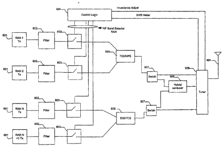
100441 Fig. 6 depicts a diverse multiple carrier aggregation schemes that uses
cross band
couplers 605 and 606 for use in bringing together multiple RF technologies and
frequency
bands of operation. RAN 1 601 could be LIE operating in the 7001VIElz upper or
lower
frequency bands. RAN 1 601 however could also be UMTS or EVDO or any other RAN
technology. RAN2 601 can be LTE, UMTS, EVDO or any RAN technology operating in
the
AWS frequency band. These RAN transmit channels are combined by use of a cross
band
coupler 605 and 606 which has very low insertion loss.
[0045] Switches 607 are included after the cross band coupler to account for
the possibility
that there may be 3 or 4 or more RI channels aggregated. The switch 607 also
if not involving
3 or 4 or more channels being aggregated in different frequency bands will
bypass the hybrid
combiner 608 reducing insertion loss.
[0046] Switches 603 after the filter 602 in Fig. 6 is meant to include the RI'
signal from the
respective RAN. When the switch 603 is in an open position its impedance will
look like and
open circuit.
100471 It is also possible to not utilize switches 603 if desired.
[0048] The tuner 609 in Fig. 6 is meant to address impedance differences that
occur when
combining different frequency bands onto an antenna 404 and can have a SWR
sensor to help
fine tune the impedance difference to maximize the transmit power,
100491 The control logic 604 is included in Fig, 6 which controls switches 603
and 607 besides
the tuner 609,
[00501 in another embodiment Fig. 7 shows another configuration for diverse
multiple carrier
aggregation where the use of two antennas 404 for transmitting is used instead
of one.
Through this configuration shown in Fig. 7 the need of a hybrid combiner 608
shown in Fig. 6
is not needed thereby improving the combining losses. The use of switches 603
may or may
not be utilized depending on impedance and isolation requirements.
8
CA 02874769 2014-11-25
WO 2013/184781 PCT/US2013/044286
[00511 Fig. 8 is yet another configuration possible where each individual
transceiver 601 is
connected to its own antenna 404. This configuration affords the least
insertion loss possible
and allows for good RF isolation for each transmitter.
[0052) Fig. 9 is another variant of the channel aggregation method where a
quad band or a N-
Plexer (N-band coupler) 901 is used to bring multiple RF bands together onto
one antenna 404.
[0053] Both Fig. 6 and Fig. 9 schemes can apply for each of the transmit
antennas that the
wireless edge device many have.
[00541 Fig. 10 is depicts the possible configuration where several quad band
or a N-Plexer (N-
band coupler) 901 is used to bring multiple RF bands together onto one antenna
404. This
configuration may be required for example when using 700 MHz Upper and Lower
bands for
diverse multiple carrier aggregation. The switch 1001 in Fig. 10 is meant to
select which Tx
path the RF signal will take. With Tx diversity the switch will enable both
paths to each of the
antennas 404 to be utilized.
[00551 Fig. 11 shows the use of two distinct Software Defined Modules 501, SDR
Transceivers to facilitate diverse multiple carrier aggregation. The SDR
modules 501 rely in
separate and diverse paths to the antenna 404 for transmission. Although only
one receive
path is shown in Fig. 11 for each SDR module 501 the use of a second antenna
404 or
potentially more antennas for receiving is possible.
[00561 Fig. 12 depicts several SDR modules 501 used for diverse multiple
carrier
aggregation. Fig. 12 shows the use of two distinct Tx paths, one for each SDR
module 501.
However the receive path to the SDR module 501 is shown coming from one or two
different
antennas 404. The use of a switch 600 is shown which enables the selection of
the antenna
404 to the appropriate SDR module enabling multiple receive paths for the SDR
to utilize.
The filter 504 is shown between th.e antenna 404 and switch 600, however the
filter 504 can
be placed after switch 600 depending on the frequency bands that the wireless
edge device
101 is designed to use. Switch 600 can also serve as a cross band coupler as
well as having
switching capabilities.
9
CA 02874769 2014-11-25
WO 2013/184781 PCT/US2013/044286
[00571 Fig. 13 is similar to that of Fig. 12 except in this configuration two
distinct RF receive
paths are defined and shown in Fig. 13. in Fig. 13 separate Rx filters 506 are
shown for each
receive path drawn
[0058] With the proliferation of RF frequency bands a wireless broadband edge
device 101
can utilize the RF receiver becomes more susceptible to unwanted energy
degrading the
receiver performance and possibly desensing the receiver itself.
[0059] Fig. 14 shows a scheme that will reduce the out of band energy that the
radio receiver
experiences by removing unwanted energy though use of band specific filters
for each of the
receivers in the wireless broadband edge device 101,
[0060] The use of a tuner or rather duplexer 1304 that is connected to an
antenna 404 which
allows for the RF energy to pass to the respective receiver portion of the
transceiver 1301.
The use or the selector switch 1310 is meant to isolate the other RI' filters
1302 interaction
resulting in an increased noise floor due to common signals.
[00611 Fig, 15 shows a scheme that will reduce the out of band energy that the
radio receiver
experiences by removing unwanted energy though use of band specific filters
for each of the
receivers in the wireless broadband edge device 101. Fig. 15 is different from
Fig, 14 in that
it utilizes several antennas 404,
[0062] Fig, 16 is another variant of the scheme shown in Fig. 15 where each
individual R.17
receive path has its own set of filters 1302 which can be added and removed
from the system.
The Rx selector switch 1320 is used to select which antenna 404 is utilized by
the transceiver
receiver 1301. The filter 1301 is capable of being static or tunable thereby
enhancing the
capability of the wireless broadband edge device for RF selectivity and
overall performance
across multiple and diverse frequency bands.
100631 Fig. 17A shows the common tuner 609 shown in many of the diagrams in
the
proposed invention. The tuner 609 is used to optimally match the antenna 404
with the
CA 02874769 2014-11-25
WO 2013/184781 PCT/US2013/044286
Transmitter or receiver for the diverse multiple carriers that the wireless
broadband edge
device may utilize. However Fig. 17B is a further refinement in that a
duplexer that has
impedance tuning capability 2000. The purpose of the duplexer is to utilize a
particular
antenna 404 for both transmission and reception of the RF energy minimizing
the amount of
antennas required for a wireless broadband edge device.
[0064] Additionally the use of a duplexer 2000 that is tunable enables more
configuration
options and opportunities for diverse multiple carrier aggregation
applications.
[0065] In Figures 6,7,8,9,10,1.4,15 and 16 the use of a tunable duplexer 2000
can be used
instead of or with the tuner 609.
[0066] Referring to FIG. 1, a wireless broadband edge device 101 will
typically
include a processor coupled to a random access memory and a wireless
transceiver
coupled to an antenna for sending and receiving voice and data calls via a
wireless
broadband network. Typical wireless broadband edge devices may also include a
rechargeable battery which provides power to the processor and transceiver,
allowing
the unit to be portable. The wireless broadband edge device may also include
components typically employed in commercial cell phones, including a display,
a
keyboard, a pointing device and a parallel or serial bus connector, all
coupled to the
processor. The wireless broadband edge devices may also include a mass storage
device coupled to the processor and random access memory, which may contain
large
amounts of data. The mass storage device or random access memory may contain
the
provisioning/programming information for mobile device operation.
[0067] It is understood that the specific order or hierarchy of steps in the
processes
disclosed is an example of exemplary approaches. Based upon design
preferences, it is
understood that the specific order or hierarchy of steps in the processes may
be
rearranged while remaining within the scope of the present disclosure. The
11
CA 02874769 2016-01-20
method according to the invention presents elements of the various steps in a
sample order, and are not meant to be limited to the specific order or
hierarchy
presented.
[0068] The hardware used to implement the forgoing embodiments may be
processing elements and memory elements configured to execute a set of
instructions, wherein the set of instructions is for performing method steps
corresponding to the above methods. Alternatively, some steps or methods may
be
performed by circuitry that is specific to a given function.
[0069] Those of ordinary skill in the art will appreciate that the various
illustrative
logical blocks, modules, circuits, and algorithm steps described in connection
with
the embodiments disclosed herein may be implemented as electronic hardware,
computer software, or combinations of both. To clearly illustrate this
interchangeability of hardware and software, various illustrative components,
blocks, modules, circuits, and steps have been described above generally in
terms
of their functionality. Whether such functionality is implemented as hardware,
firmware, or software depends upon the particular application and design
constraints imposed on the overall system. Those of ordinary skill in the art
may
implement the described functionality in varying ways for each particular
application.
[0070] The steps of a method or algorithm described in connection with the
embodiments disclosed herein may be embodied directly in hardware, in a
software module executed by a processor, or in a combination of the two. The
software module may reside in a processor readable storage medium and/or
processor readable memory both of which may be any of RAM memory, flash
memory, ROM memory, EPROM memory, EEPROM memory, registers, hard disk,
12
CA 02874769 2015-12-16
=
a removable disk, a CD-ROM, or any other tangible form of data storage medium
known in the art. Moreover, the processor readable memory may comprise more
than one memory chip, memory internal to the processor chip, in separate
memory
chips, and combinations of different types of memory such as flash memory and
RAM memory. References herein to the memory of a mobile device are intended to
encompass any one or all memory modules within the mobile device without
limitation to a particular configuration, type, or packaging. An exemplary
storage
medium is coupled to a processor in the mobile device such that the processor
can
read information from, and write information to, the storage medium. In the
alternative, the storage medium may be integral to the processor. The
processor
and the storage medium may reside in an ASIC.
[0071] The foregoing description of the various embodiments is provided to
enable any person skilled in the art to make or use the present invention.
Various
modifications to these embodiments will he readily apparent to those skilled
in the
art, and the generic principles defined herein may he applied to other
embodiments. Thus, the present invention is not intended to be limited to the
embodiments shown herein.
13