Note: Descriptions are shown in the official language in which they were submitted.
CA 02874989 2014-11-27
WO 2013/180818
PCT/US2013/031998
Deep-MALDI TOF mass spectrometry of complex biological samples, e.g.,
serum, and uses thereof
Cross-reference to related application
This application claims priority benefits under 35 U.S.C. 119 to US.
provisional
application serial no. 61/652,394 filed May 29, 2012. the content of which is
incorporated by
reference herein.
Background
This disclosure relates to the fields of mass spectrometry, biomarker
discovery, assay
development, and clinical testing.
Current technology
In 1vLALDI (matrix assisted laser .desorption ionization) TOF (time-of-flight)
mass
spectrometry, a sample/matrix mixture is placed on a defined location ("spot",
or "sample
spot" herein) on a metal plate, 'blown as a .MALDI plate. A laser beam is
directed onto a
location on the spot for a very brief instant (known as a "shot"), causing
desorption and
ionization of molecules or other components of the sample. The sample
components "fly" to
an ion detector. The instrument measures mass to charge ratio (fiVz) and
relative intensity of
the components (molecules) in the sample in the form of a mass spectrum.
Typically, in a MALDI-TOF measurement, there are several hundred shots applied
to
each spot on the MALDI plate and the resulting spectra (one per shot) are
summed or
averaged to produce an overall mass spectrum for each spot. U.S. patent
7,109,491 discloses
representative MALDI plates used in MAT DI-TOF mass spectrometiy. The plates
include a
multitude of individual locations or spots where the sample is applied to the
plate, typically
arranged in an array of perhaps several hundred such spots.
The conventional wisdom, at least in the area of mass spectrometry of complex
biological samples such as serum and plasma, is that there is no need to
subject the sample to
more than roughly 1,000 shots, otherwise the protein content is depleted, the
laser and
detector in the instrument are subject to undue wear, and furthermore that
additional shots
1
CA 02874989 2014-11-27
WO 2013/180818
PCT/US2013/031998
would not reveal a significant amount of additional information regarding, the
sample.
Hence, it is common to use 500-1000 shots per sample spot when obtaining mass
spectrometry data from complex biological samples, e,g., during biomarker
discovery.
research.
The 'Rather of detectable proteins in standard MALDI-TOF MS of serum or plasma
is believed to be limited by the large dynamic. range of abundance of proteins
in circulation.
(Hortin G.L., The MALDI-TOF mass spectrometric view of the plasma proteome and
peptidome. Chu. Chem. 2006; 52:1223-37). Hence it is commonly believed that
MALDI-
TOF MS of serum is only possible for high abundance proteins in the range of
micromoles
per liter. This is counter to the observation that MALDI-TOF mass spectrometry
can be a.
very sensitive technique to detect even trace amounts in purified samples.
(Albrethsen Jr. The
first decade of MALDI Protein profiling: A lesson in translational biomarker
research. J.
Proteomics 2011 74: 765-73). This patent application explains this discrepancy
and provides
methodology to extend the high sensitivity of MAT DI-TOF MS from simple
samples to
complex biological samples such as serum or plasma.
U.S. Patent 7,736,905, assigned to the assignee of the present invention,
describes
among other things methods for peak identification, spectral alignment,
normalization and
other pre-processing techniques for mass spectra of biological (e,g., serum)
samples and uses
thereof in predicting patient response to administration of anti-cancer drugs.
The '905 patent
is incorporated by reference herein in its entirety.
Summary
In recent exploratory studies, the present inventors have discovered that
collecting and
averaging many (more than 20,000, and typically 100,000 to 500,000) shots from
the same
IvIALDI spot or from the .combination of accumulated spectra from multiple
spots of the same
sample, leads to a reduction in the relative level of noise vs, signal and
that significant
amount of additional spectral information from mass spectrometry of complex
biological
samples is revealed. Moreover, a variety of standard paradigms using IvIALDI
TOF MS
appear to be plain wrong. First, it is possible to run hundreds of thousands
of shots on a
single spot before the protein content on the spot is completely depleted.
Second, the
reduction of noise via averaging many shots leads to the appearance of
previously invisible
peaks peaks
not apparent at 1,000 shots). Third, even previously visible peaks become
better defined and allow for more reliable measurements of peak intensit-,,,;
and comparisons
2
CA 02874989 2014-11-27
WO 2013/180818
PCT/US2013/031998
between samples when the sample is subject to a very large number of shots
(much more than
1,000).
As an example, the present inventors have made the surprising discovery that
when a.
serum or other blood-based sample is subject to MALDI-TOF at greater than
20,000 shots
per spot. and typically 250,000 or more shots per spot, and even 2.800,000
shots using
multiple .MALDI spots, each experiment shows that the protein content of the
spot was not
rendered unusable. It was further discovered that a very significant amount of
spectral
information (peaks) is contained in the spectra obtained at these numbers of
shots, which are
not revealed when the sample is subject to the typical 500 or 1,000 shots. The
peaks revealed
at, for example, 200,000 shots are believed to correspond to minute quantities
of intact
(undigested) proteins present in the serum sample. Using the techniques
described herein and
what is referred to herein as the "deep-NULDI" approach (i.e., greater than
20,000 shots per
spot, and preferably roughly 250,000 to 750,000 or more shots from the same
spot or from.
the combination of multiple spots), it is believed that a very large number of
proteins, and
possibly at least half of all the proteins present in a serum sample, can be
detected in a semi-
quantitative and reproducible fashion. The detection in a semi-quantitative
fashion means
that the measurements of intensity (peak height, area under the peak) are
related to the
absolute abundance or concentration of the proteins in the sample. The
detection in a.
reproducible fashion means that one can measure the same sample many times and
one
obtains the same results within some acceptable coefficient of variation.
Obtaining more than 20,000 shots from a single NLALDI spot can exceed the
parameters of a modem MALDI-TOF machine; however we describe in this document
several methods of working around this limitation. Ideally, the MALDI-TOF
instrument is
designed to accommodate the "deep-.MALDI" approach described in this document,
and
several specific proposals for such a machine are offered in the following
description,
including automated raster scanning features and capability of performing
vastly more shots
on a single spot.
The most pressing issue using many hundreds of thousands of shots from a.
MALDI
sample spot is that in common spot preparation only some shot locations within
a spot yield
sufficient ion current to contribute substantially to signal in a combined
spectrum. While
initial results have been obtained using a..a...) I
or intensive manual process to visually select
high ion yield locations within a given spot on a iN4ALDI plate for laser
shots, and it is
3
CA 02874989 2014-11-27
WO 2013/180818
PCT/US2013/031998
possible to proceed with this approach, automation of the process to select
locations for laser
shots is possible and preferred for a high throughput implementation of the
invention (if not
for the simple reason to not waste too many laser shots and degrade the laser
life time
substantially). An alternative approach is to improve the quality of NIALDI
spots in such a
way that most randomly selected locations yield a high ion current. Both
approaches are
useful in the generation of deep-MALDI spectra.
Several methods for automation of spectral acquisition are described in this
document.
Automation of the acquisition may include defining optimal movement patterns
of the laser
scanning of the spot in a raster fashion, and generation of a specified
sequence for multiple
raster scans at discrete X/Y coordinate locations within a spot to result in
say 750,000 or
3,000,000 shots from one or more spots. For example, spectra acquired from
250,000 shots
per each of four sample spots can be combined into a 1,000,000 shot spectrum.
As mentioned
previously, hundreds of thousands of shots to millions of shots collected on
multiple spots
containing the same sample can be averaged together to create one spectrum.
One method of
automation involves the generation of raster files for non-contiguous .X.,Y
raster scanning of a
sample spot. Another method involves dividing the spot into a grid of sub-
spots (e.g,, a 3X3
or 5X5 grid) and generating raster files for raster scanning at discrete X/Y
coordinate
locations of the sub-spots. A third method is disclosed using image analysis
techniques to
identify areas of interest containing relatively high concentrations of sample
material for
spectral acquisition (multiple shots) and/or those areas where the protein
concentration is
relatively low, and performing spectral acquisition in the areas with
relatively high protein
concentration.
A further aspect of this disclosure relates to optimizing the process of
sample
application to the MALDI plate (-spotting") to produce uniform, homogeneous
crystals of the
sample/matrix within a single spot. This process facilitates Obtaining
hundreds of thousands
of shots from a single spot on the 1vIALDI plate using automated methods..
This discovery and methods of this disclosure has many applications, including
biomarker discovery, test development, substance testing, validation of
existing tests, and
hypothesis generation, e.g., in biomarker discover), efforts. The methods
further enhance the
potential of "dilute and shoot" methods in mass spectrometry research by its
ability to
reproducibly quantify the amount of many more proteins in a. complex sample in
a high
throughput fashion, as compared to current methodologies. For example, the
methods can be
4
CA 02874989 2014-11-27
WO 2013/180818
PCT/US2013/031998
used in testing for doping of sports athletes, drug testing, e.g., for
detection of THC analytes,
metabolite testing, testing for presence and amount of cancer antigen 125 (CA-
125), prostate
specific antigen (PSA) or C-reactive protein, and environmental or food
testing. Other
examples of applications include the development of clinical tests based on
the protein
content of clinical samples from retrospective samples of patients via
correlative studies, and
follow-up clinical validation.
Terminology used in this document:
1. The term "transient spectrum" refers to the spectrum obtained from a
single
packet of laser shots directed to a single location or xly position (each
packet consists of a.
defined number of shots, e.g. 100, 500, 800 shots, etc.) in a MALDI spot.
2. The term "location spectrum" refers to the cumulative sum of one or more
transient spectra while the laser shoots x times at the same location in a
.MALDI spot.
3. The term -spot spectrum- refers to the sum of all the location spectra
acquired
during shooting over an entire, single MALDI spot. The spot spectrum can be
obtained using
solely a summing operation to sum the location spectra, or obtained using a
summing
operation after performing alignment and/or normalization operations (e.g.,
total ion current
normalization) on the location spectra. The spot spectrum can be typically
obtained from
100,000 to 500,000 shots on the MALDI spot. Other options for obtaining the
spot spectrum
are possible, including a) performing background subtraction and normalization
on the
location spectra and then summing: b) performing background subtraction and
alignment on
the location spectra and then summing: c) performing background subtraction,
alignment, and
normalization of the location spectra and then summing. We have found that the
best
dynamic range is achieved by total ion current normalization (for details see
U.S. Patent
7,736,905) of location spectra and then summing: any background subtraction
would be done
in the spot spectrum.
4. The term "shot location" refers to a given location where the laser beam
intercepts
a MALDI spot for Shooting. In order to obtain 200,000 or 500,000 shots per
MALDI spot the
laser beam is directed over the MALDI spot to a multitude (e.g., hundreds) of
individual shot
locations, e.g., manually, or more preferably in an automated fashion using
raster scanning of
the laser beam over the spot. As explained below, the raster pattern design is
important as it
is generally undesirable to shoot immediately adjacent spot locations
sequentially. Hence,
5
CA 02874989 2014-11-27
WO 2013/180818
PCT/US2013/031998
the raster pattern design sequentially selects shot locations that have some
spatial separation
and repeats the scanning over the entire MALDI spot in a spatially shifted
manner to avoid
sequential shooting of immediately adjacent locations in the spot.
5. The term -transient spectrum filtering- refers to a filtering or
selection process
that is used to either accept or reject a transient spectrum. As an example,
in transient
spectrum filtering, in order for a transient spectrum to be accepted a minimum
number (e.g.,
5) of peaks within a predetermined iniz range must be present in the transient
spectrum, and
the signal to noise ratio in the transient spectrum must be above a specified
threshold. Other
filtering criteria can also be used, such as the total ion current of a
spectrum needs to exceed a
certain predefined threshold. or by using exclusion lists or inclusion lists
as explained below.
The spectrum filtering either accepts or rejects the transient spectrum in
whole.
6. As used herein, the term -complex biological samples- is defined as
samples
containing hundreds or thousands of analytes, e.g., intact proteins, whose
abundance is spread
over a large dynamic range, typically many orders of magnitude. Examples of
such complex
biological samples include blood or components thereof (serum or plasma),
lymph, ductal
fluids, cerebrospinal fluid, and expressed prostatic secretion. Such
complex biological
samples could also consist of environmental or food samples.
Brief description of the drawings
Figures IA-IC are an illustration of three MALDI mass spectra of the same
sample in
a selected mass/charge range (i.n/z ratio 7,000 to 8,000'i, illustrating the
increase in detectable
peak content with increasing number of shots. The spectrum of Figure 1 A
resulted from
2.000 shots, the spectrum of Figure 1B resulted from 100,000 shots. and
spectrum of Figure
IC resulted from 500,000 shots. Note how the spectra of Figures 1B and IC,
resulting from
our methods, reveal a wealth of spectral information on the sample which was
not present in
the spectrum of Figure 1A, which appears essentially as noise.
Figures ID and 1E are further examples of mass spectra showing the enomfous
dynamic range of spectra obtained in our deep-MALDI method, In Figure ID, a
portion of
the spectrum in an iniz range from 7140 to 7890 Da is shown enlarged in the
inset of Figure
ID showing a wealth of spectral information obtained at approximately 500.000
shots. In
Figure IF, the spectrum is shown in the inset with the Y axis amplified in
order to show
6
CA 02874989 2014-11-27
WO 2013/180818
PCT/US2013/031998
additional spectral information and peaks in the region of nilz around 9520,
which are
revealed with the deep-1\4AM' method but which are not visible in a typical
¨1,000 shot
spectrum.
Figure 2A is a plan view of a MALDI-TOF target plate containing 384 sample
spots
or "spots" arranged in a rectangular may. The spots are identified by column
numbers 1. . .
24 and rows A . . P, e.g., the upper left spot is identified as Al, Figure 2B
is an enlarged
view of an individual sample spot P1 which is shown divided into a 5X5
rectangular grid
having .XIY location coordinates and an origin (0,0) at the center of the
spot. The rectangular
grid and location coordinates are used in an automated raster scanning
approach to acquire
spectra from 100,000 or more shots from the spot as described in detail
herein.
Figure 3 is a photograph of a biological sampleimatrix mixture deposited in a
single
spot in the MALDI plate of Figure 2A. Ideally, the spot contains a uniform,
homogenous
crystallized sample within the spot, as shown in Figure 3,
Figure 4 is an illustration of one possible raster scanning pattern for use in
obtaining
100,000 or more shots from the spot of Figure 3, The spot is raster scanned
multiple times,
e.g.. 25 times. Each symbol set (triangle, square, X, etc.) Shown in Figure 4
depicts a set of
individual., discrete X/Y locations where the spot is scanned (shot) in a
single raster scan. At
each location, the spot can be subject to multiple shots, e.g., 700 or 800
shots.
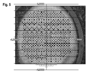
Figure 5 is an illustration showing the superposition of the raster scanning
pattern of
Figure 4 on the sample spot of Figure 3..
Figure 6 is a screen shot from a MALDI-TOF instrument user intertice showing
commands for summing accumulated spectra from 800 laser shots per
location/raster, e.g., in
the raster scanning of Figures 2B or 5.
Figure 7 is an image of a portion of a sample spot showing areas where the
sample/matrix mixture does not crystallize in a. spatially uniform manner.
Figure 8 is a screen shot from a MALDI-TOF instrument user interface showing
an
image of a portion of a spot captured by a camera in the instrument, and the
selection of a
gxoup of spots for automated raster scanning of the spots.
7
CA 02874989 2014-11-27
WO 2013/180818
PCT/US2013/031998
Figure 9 is another screen shot from a MALDI-TOF instrument user interface
showing tools for evaluation of spectra, accumulation of spectra, and movement
of a laser
across a spot for firing in different patterns.
Figure 10 is a screen shot of an evaluation page for accepting or rejecting
transient
spectra during data acquisition.
Figure 11 is a screen shot showing exclusion lists for eliminating backgjound
peaks..
Detailed Description
1. Overview
It has been discovered that subjecting a complex biological sample, such as
for
example a blood¨based sample, to a large number of shots on a single spot (>
20,000 and
even 100,000 or 500,000 shots) in .NIALDI-TOF mass spectrometrv leads to a
reduction in
the noise level and the revealing of previously invisible peaks (i.e., peaks
not apparent at
2,000 Shots). Moreover, this can be done without depletion of the protein
content of the
sample. Additionally, previously visible peaks become better defined and allow
for more
reliable comparisons between samples. In standard spectra of blood-based
samples (-1,000
shots), typically 60-80 peaks are visible, whereas with 200,000 shots
typically ¨200-220
peaks are visible, with 500,000 shots typically ¨450-480 peaks are visible,
and with
2,800,000 shots .typically ¨760 peaks are visible. It should be understood
that the number of
peaks reported here is related to IvIALDI-TOF instillment settings and these
numbers are only
a rough guide: depending on instrument settings and also on particular peak
detection
algorithms (and of course the actual sample) more Of fewer peaks will be
visible. It also must
be noted that the quality of peaks and the quantification of intensity
(related to abundance) is
also better at least ander some measure, as is illustrated in Figures IA-1D
discussed below.
Figures 1A-1C are the plots of a selected mass/charge range (mlz ratio 7,000
to 8,000)
showing three spectra of the same sample (serum) illustrating the increase in
detectable peak
content with increasing number of Shots. The spectrum of Figure IA resulted
from 2,000
shots, the spectrum of Figure 1B resulted from 100,000 shots, and the spectrum
of Figure IC
resulted from 500,000 shots. Note particularly how the spectrum of Figure 1A
appears
essentially as noise and appears to contain little or no discernible spectral
information of
8
CA 02874989 2014-11-27
WO 2013/180818
PCT/US2013/031998
interest. Contrast Figure lA with 1B in which the spectrum of Figure 1B
(spectrum
obtained from 100,000 shots) contains many individual peaks, e.g., the peaks
identified at
10), that are not present in the spectrum of Figure 1A. In the spectrum of
Figure IC, there
are many peaks shown in the spectrum that are not Shown in the other spectra,
or which might
have been deemed as noise in the bottom spectrum. Comparing Figures 1C and 1B
to Figure
1A, it is apparent that a wealth of spectral information is revealed at
100,000 shots and
500,000 shots that is not present in the spectrum of Figure IA (2,000 shots),
and that the
noise level is reduced by the deep-MALDI method as demonstrated in Figures 1B
and IC.
The spectra of Figures 1B are IC increase the sensitivity of the spectra to a
dynamic
range that can be specified and can allow one to correlate peak intensity to
abundance. It is
possible to use peak intensity to analyze a complex biological sample for
presence of a.
molecule at a given concentration. For example, in this method one would
define the
molecule of interest (of known mass) in the sample, dope the specimen to a
target abundance
level (molar concentrations, or ppm) and apply to a MALDI plate; perform a
number of shots
on the plate (e.g., more than 100,000) until the molecule is reliably present
in the spectrum (a
peak at a known infz position) at a particular abundance (intensity), and
record the number of
shots ("x"). This procedure to generate what is referred to as a -reference
spectrum" would
be subject to routine qualification and standardization methods to ensure
reliability, as would
be apparent to persons skilled in the art. Then, a sample of interest for
testing would be
subject to MALDI-TOF and x number of shots. If the resulting spectrum revealed
that the
intensity of the peak at the known position corresponding to the molecule of
interest was less
than the intensity of the peak in the reference spectrum then the
concentration of the molecule
of interest in the sample is less than the concentration of the molecule in
the sample used in
generation of the reference spectrum. This approach could be used for multiple
analytes
simultaneously. Furthermore, multiple reference spectra could be obtained for
the molecule
of interest over a range of known concentrations at x shots and the test
spectrum could be
compared to the reference spectra to determine an approximate concentration of
the molecule
of interest in the test sample. This method can be used for many purposes,
e.g., drug testing,
e.g., for athletes, testing of metabolite concentration, environmental sample
testing, etc. The
molecule of interest could be a protein, e.g., metabolite, cancer antigen (CA)
125, prostate-
specific antigen (PSA), C-reactive protein, etc., in a mass range of
approximately IK Daltons
to 50 K Daltons,
9
CA 02874989 2014-11-27
WO 2013/180818
PCT/US2013/031998
Figure ID is an illustration of the enormous dynamic range in a spectrum that
is
revealed in the deep-MALDI approach. The inset in Figure ID is a portion of a
spectrum in
the miz range between 7140 kDa and 7890 kDa. Showing the spectrum, and
multitude of
peaks 10, obtained at about ¨500,000 shots. A background estimate (dashed
line) is
superimposed over the spectra, which could be subtracted out to produce a
background.
subtracted specumn. Note that the spectrum information in the inset and in
particular many of
the peaks 10 are not visible in the main portion of Figure ID. In Figure 1E,
the spectrum is
shown in the inset with the Y axis amplified in order to show the additional
spectral
information and in particular intensity information for peaks in the region of
ni/z around 9520
which are revealed with the deep-MALDI method but which are not visible in a
.typical
¨1,000 shot spectrum.
Figure 2A is a plan view of a MALDI-TOF target plate 12 containing 384 sample
spots or "spots" 14 ananged in a rectangular array. The spots are identified
by column
numbers 1 . . . 24 and rows A. . P. e.g., the upper left spot is identified as
Al. Figure 2B is
an enlarged view of an individual sample spot PI (14) on which is superimposed
an X/Y
coordinate system 16 having an origin (0,0). The sample spot 14 is shown
divided into a 5X5
rectangular grid 25 individual sub-spots 18. The rectangular grids 18 and
location coordinate
system 16 are used in an automated raster scanning approach to acquire 100,000
or more
shots from the spot as described in detail below.
It was initially noted that automated generation of a large number of shots
("> 20,000)
is not absolutely necessary and existing features in currently available MALDI-
TOF
instruments could be used. In general, in the present deep-MALDI technique, it
is important
to select locations on a MALDI spot that produce a high protein yield when
exposed to a.
laser shot. The standard software in existing mass spectrometry instruments
allows for
moving over a spot using regular pre-defined paths, i.e. square pattern,
hexagonal pattern,
spiral pattern (from the center of a spot). Shot locations on a MALDI plate
are defined in a
process called 'teaching', a part of the FlexControlTM (Braker) mass spec
control software
present in an existing MALDI-TOF instrument of Bruker Corporation. (While
mention is
made herein occasionally to features of a Milker Corporation instrument, the
inventive
methods are of course not limited to any particular instrument or instruments
of a particular
manufacturer.)
10,
CA 02874989 2014-11-27
WO 2013/180818
PCT/US2013/031998
An example of a MALDI spot containing a specimen/matrix mixture evenly
distributed within the spot is shown in Figure 3. Mass spectrometry
instruments from Braker
Corporation include a built-in camera that shows areas of a .MALDI spot; in
manual selection
one would pick bright locations 30 to aim the laser at. Dark locations 32
should be avoided.
Sometimes bright locations do not produce good yields, which may be related to
the presence
of salt crystals. Over the process of shooting, areas in a spot can become
depletedk hence
dark areas (depleted areas with low yield) need to be avoided. The manual
approach would
continue to acquire and display images of the spot over the course of
shooting.
In the course of our preliminary experiments we found that it was becoming
increasingly harder to find good locations as more and more shots were used.
This effect was
also seen when the same spot was used repeatedly, e.g. adding a second half
million shots
following a previous half million shots. The second run did not result in as
much a reduction
of noise level in mass spectra as was expected. hi thct, the resulting
averaged spectra may be
of worse overall quality, possibly arising from averaging shots from too many
empty
locations.. This might result in an acquisition bias towards early locations
if using the eye
alone to select Shot locations and accept or reject spectra and not using
transient spectrum
filtering, and such bias needs to be controlled. If one uses automated raster
scanning and
location spectrum filtering this bias is eliminated.
However, to increase throughput, it is desirable to automate the process of
location
selection and obtain high numbers of shots from a given spot. Several methods
are described
in the following section. Methods described below are capable of acquiring
750,000 Shots
from a sample located on three spots (250,000 shots per spot) in a MALDI plate
in 13-1.5
minutes, with the sample requirement of 3 microliters of serum.
2. Automation of spectra collection
While results have been obtained using a labor intensive manual process to
visually
select locations within a given spot on a MALDI plate for multiple shots to
yield 100,000 or
500,000 shots per spot, and it is possible to proceed with this approach,
automation of the
process to select locations for laser shots is possible and several methods
are described in this
document, Automation of the acquisition may include defining optimal
movement
patterns of the laser scanning of the spot in a raster fashion, and sequence
generation for
CA 02874989 2014-11-27
WO 2013/180818
PCT/US2013/031998
multiple raster scans at discrete XlY locations within a spot to result in,
for example,
100,000, 250,000 or 500,000 shots from the sample spot. One method of
automation
involves the generation of raster files for non-contiguous XlY raster scanning
of a sample
spot. The
raster pattern design is important, as it is generally undesirable to shoot
immediately adjacent spot locations sequentially. Hence the raster pattern
design
sequentially selects shot locations that have some spatial separation and
repeats .the scanning
over the entire MALDI spot in a spatially shifted manner to avoid sequential
shooting of
immediately adjacent locations in the spot and to select new shot locations.
Another method involves dividing the spot into a grid of sub-spots (e.g., a
3X3 or 5X5
grid) (see Figure 2B) and generating of raster scanning files for raster
scanning at discrete
XlY locations of the sub-spots.
A third method is disclosed using image analysis techniques to identify areas
of
interest containing relatively high concentrations of sample material for
spectral acquisition
(multiple shots) and/or those areas where the sample (e.g.., protein)
concentration is relatively
low, and avoiding spectral acquisition in areas of relatively low sample
(e.g., protein)
concentration..
A. Raster scanning of non-contiguous X-Y coordinates
One method of automation of the process of obtaining a large number of shots
from a
spot involves the generation of raster files for non-contiguous .MY raster
scanning of a
sample spot. This will be described in conjunction with Figures 4 and 5.
Figure 4 is an illustration of a raster scanning pattern 400 for use in
obtaining 100,000
or more shots from the spot 14 of Figure 3. The spot 14 is raster scanned
multiple times, e.g..,
times in a sequential fashion. The symbol sets shown in Figure 4 depict
individual,
25 discrete .X(Y locations where the spot is scanned (shot) in a single
raster scan. The XN
locations are defined according to a coordinate system shown in the Figure
having an origin.
at the center (position 0,0). During scanning, when the laser is directed to
each location, the
sample at that location can be subject to a great many shots, e.g,, '700 or
800 shots per
position/location One will note from the pattern shown in Figure 4 that each
raster scan
consists of shooting at individual, discrete locations within the spot. The
individual raster
scans are implemented sequentially thereby avoiding shooting immediately
adjacent locations
12
CA 02874989 2014-11-27
WO 2013/180818
PCT/US2013/031998
in the spot. Figure 5 shows the superposition of the raster patterns of Figure
4 over the spot
of Figure 3.
A procedure for generation of 25 raster files with non-contiguous X/Y
coordinates for
raster scanning as shown in Figure 4 is described in Appendix 1, which is part
of this
disclosure.
B. Use of grids to separate a spot into sub-spots and raster
scanning of sub-spots
An objective of this method is to automate the process of manually selecting
locations/rasters on a sample spot (i.e. spot Al, spot A2, etc.) that result
in "acceptable"
spectra during data acquisition and to do this until several hundred thousand
spectra have
been added to the sum butler. Summing up/averaging several hundred thousand
spectra
increases the signal to noise ratio, and therefore allows for the detection of
significantly more
peaks, as described previously.
As is the case with non-contiguous raster scanning, described above, the use
of grids
as described in this section works best when the sample/matrix mixture is
substantially
evenly and homogeneously distributed over .the entire spot, as shown in Figure
3. A
presently preferred method for achieving this is described later in this
document for dilute-
and-shoot serum and sinapinic acid (matrix). Because of this even
distribution, we can
therefore acquire spectra from virtually all locations/rasters on the sample
spot, which.
eliminates the need for a precursory evaluation of all locations/rasters for
"acceptable"
spectra.
Collecting several hundred thousand spectra on a sample spot can be achieved
by.
defining a grid (Figure 2B) that subdivides the spot 14 into sub-spots or grid
elements 18, that
covers the sample spot, and collecting a defined number of spectra from each
location/grid
point/raster within each sub-spot 18 until the desired number of spectra have
been added to
the sum buffer. Previous versions of the Bruker software only allowed for the
summation of
a maximum of 20,000 total spectra per sample spot in automatic. mode (Figure
6.)
To circumvent this limitation we initially defined a 5 by 5 grid area. (Figure
2B, 16)
that divides each sample spot into twenty-five 8 x 8 grids or sub-spots 18
(Figure 2B). A
separate raster file is generated for each gid or sub-spot 18. The instrument
is instructed to
13
CA 02874989 2014-11-27
WO 2013/180818
PCT/US2013/031998
acquire 800 spectra (shots) at each location/raster within a grid 18 until
20,000 spectra have
been added to the (spectrum) sum buffer. At that time, the automatic method I
instructs the
instrument to move to the next grid or sub-spot 18 and use the next raster
file and generate
another 20,000 spectra, In practice, one designs 25 raster files, one for each
sub-spot 18,
each of which is attached to a separate autoExecuteTM (Braker) method that
acquires data.
according to evaluation criteria setup within the method.
This procedure permits acquisition of 500,000 shot spectra (20,000 shot
spectra per
grid x 25 grids) in batches of 20,000 shots each using Brakes flexcontrolTM
software tools
without having to use imaging applications such as flexImagingTM (Braker). The
result of
this procedure is 25 spectra files for one sample spot each containing one
summed spectrum
composed of 20,000 shot spectra. These 25 spectra tiles can then be summed to
produce an
overall spectrum for a single spot on a MALDI plate obtained from 500,000
shots, e.g., as
shown in Figures IC, ID and 1E.
The most recent version of flexcontrol TM (Braker) allows one to accumulate a
summed spectra from up to 500,000 shots. For example, in Figure 6 the
autoExecuteTM
(Braker) method editor allows the summation of 20,000 shots in 800 shot steps
(800 shots per
location/raster).
However, one can only collect one summed spectra (sum of x transient spectra)
per
sample spot. To acquire several batches of summed spectra from a single sample
spot. we
had to make adjustments to existing software features in the MS instrument.
With these
adjustments we can acquire spectra from one or several rasters that makes up a
grid such as
the ones described above, and save each transient or location spectrum
individually. For
instance, the instrument can be instructed to collect and save each 800 shot
location spectra.
acquired at each raster (x,y position) in the grid or sub-spot 18 in Fig 2B
without having to
add to the sum buffer. The same process is repeated for all the sub-spots
within the sample
spots AI õk2õk3 etc. (e.g. 800 shot spectra can be acquired from 250 rasters
per sample spot
= 200,000 shots per sample spot). The location spectra can be acquired with or
without
applying spectrum filtering in autoExecute TM (Braker).
C. Image analysis
14
CA 02874989 2014-11-27
WO 2013/180818
PCT/US2013/031998
One option for automation of spectral acquisition is image processing
techniques to
identify spatial locations on a spot with high protein yield/high sample
concentration
particularly in the situation where the sample is not spatially evenly
distributed over the spot
and instead is concentrated in discrete areas. In one possible embodiment, the
camera
included in the instrument is used to acquire an optical image of a training
spot. Then, mass
spectra are acquired from a raster of locations on the training spot.
Resulting mass spectra
are used, in combination with the optical image of the spot, to generate a
classification.
mechanism to detect, from the optical image, high yield locations of further
spots prepared
from a given sample preparation. This classification would then be applied to
the actual
sample spots. While this is an elegant sohttion, we encountered issues with
capturing the
camera feed, and the repeatable calibration of locations from camera images to
laser shot
locations.
An alternative method is to investigate a spot using the mass spectrometer
directly in.
the form of a mass spectral imaging approach. The idea. is to first run a
preliminary scan and
shoot a low number of shots (dozens) at each location of a fine scale (square)
pattern on a
spot. Spectra will be collected for each of these raster locations, and the
total ion current, or
ion current within some predefined range of .mlz, will be recorded for each
location. A new
raster file will be generated based on the N highest intensity locations from
the preliminary
scan run, and used in the final acquisition of mass spectra. This approach
utilizes the Bruker
.FlexImagingTM software as the most feasible solution to generate multiple
spectra in the
mass spec imaging run. Software analyzes these spectra, and generates a final
raster scan
pattern. While this method will likely be useful for standard dilute and shoot
processes using
sinapinic acid as a matrix, it might be suboptimal for other matrices and for
pre-fractionated
sample sets (e,g. CLCC.A, see Leszyk, J.D. Evaluation of the new MALDI Matrix
4¨Chloro-
a-Cyanocinnamic Acid, Bimolecular Techniques, 21:81-91 (2010)), and other
methods
like NOG precipitation (Zhang N.et al., Effects of common surfactants on
protein digestion.
and matrix-assisted laser desorption/ionization mass spectrometric analysis of
the digested
peptides using two-layer sample preparation. Rapid Commun. Mass Spectrorn.
18:889-896
(2004)). An important aspect of this alternative method is to find acquisition
settings in the
MS imaging part so as to not generate too large files. A standard acquisition
file is of the
order of one megabyte, and for a 400 by 400 raster scan (400 locations, 400
shots per
location) we generate 16,000 spectra, As the requirements for these spectra
are not onerous at
all, and we only need to estimate the total ion current, we can work with low
resolution.
CA 02874989 2014-11-27
WO 2013/180818
PCT/US2013/031998
settings. It may be possible to directly obtain a list of usable locations
from automatic
spectral acquisition settings, i.e. getting a list of successful or failed
acquisitions. From our
investigations it appears that it may be possible to use mass filtering as
part of the MS
imaging package to generate a list of locations (recognized via a file list)
that pass certain
criteria, While this will greatly help with the generation of a prototype
workflow, it will need
to be optimized via specialized software to avoid a semi-manual process.
Figure 7 shows a region of a 11.1ALDI spot using CLCCA as a matrix, where the
high
yield areas consist of linear structures and areas of low yield are Shown as
dark areas. For
these cases, where the matrix sample crystallizes very unevenly, like Shown in
Figure 7, the
image analysis approach seems most sensible. The image analysis identifies the
relatively
high yield areas (120, 122). The relatively low yield areas, such as the areas
124 on the
lower left and the matrix area 126 are identified by the image analysis
software and are
ignored during shooting.
The image analysis software to identify high and low yield areas on a spot
could take
a variety of thrills, and can be developed by persons skilled in the art. For
example, the black
and white image of the spot (Figure 7) consists of an array of pixels, each
having an 8 bit
quantized value, with 0 being black (no signal) and 255 being white
(saturated). The filtering
can be used to identify areas of relatively high yield, such as by identifying
pixels with a
pixel value greater than say 100 being identified as -high yield- and pixels
having a pixel
value lower than 40 being identified as relatively -low yield". The scanning
then proceeds to
those areas of the sample spot in which the conesponding pixel has a value of
100 or more. It
may also be possible to filter out spot locations in which the pixel value is
240-255 as such
areas may be determined to have salt crystals or other properties that result
in low yield.
Referring again to Figure 7, the pixels for the crystalline structures 120,122
have pixel values
falling in the range of 100-240 and thus would be scanned whereas the black
areas 124 and
126 would not be, Morphological processing techniques could also be used to
identify
structures such as the crystals 120 of Figure .7. The image analysis software
could include
both morphological processing and filtering to determine areas to scan.
Additionally, the
spot can change during the course of scanning (due to depletion of the sample)
and the image
processing can be run during the scanning to optimize the shooting over the
course of
generating 100,000 or more shots from a spot, and those locations of low
sample
concentration avoided during shoot-Mg.
16
CA 02874989 2014-11-27
WO 2013/180818
PCT/US2013/031998
Figure 8 is a screen shot from a MALDI-TOF instrument showing the display of
the
instrument workstation 130, including an image 132 of a spot 14, in this case
spot F1.7 of the
plate. The layout of the plate is shown at 12', with the spot F17 indicated at
14'. A group of
spots 134 (D9 to F20) are selected for running in an automatic mode using the
image analysis
method described above.
Figure 9 is another screen shot from the instrument. Current instruments allow
the
user to set evaluation regions to accept or reject transient spectra (using
the Evaluation tab),
set how many spectra to accumulate per spot (using the _Accumulation tab) and
"move"
across the spot so that the laser can fire in a certain pattern (using the
"Movement" tab,
shown). The options include random walk or movement in pattern, e.g., hexagon
or spiral.
The software also allows the user to keep firing the laser and acquiring and
adding to the total
spectra according to such parameters until spectra from 750 Shots are
collected from a shot
location, and then move to the next shot location. One can set the number of
tries before the
shot location is considered a filed spot. The image analysis methods in which
likely areas of
low yield are identified, and shooting in those areas avoided, helps in
considerably reducing
or eliminating those failed judgments.
Figure 10 shows an evaluation page where a mass range for accepting or
rejecting
transient spectra is selected, as indicated at 150. During acquisition, if a
transient spectra
does not have peaks in the predefined range - in this case 5,000 to 18,000 Da,
that pass the
threshold set (based on resolution, signal intensity or other factors), then
it will be rejected..
That is, the transient spectra will not be added to the sum buffer to form the
location spectrum
(summing the spectra from all of the shots).
Figure 11 shows an evaluation page where if there are specific peaks that one
does not
want included in the evaluation one can make an exclusion list and tag these
peaks as
"background peaks." The software has predefined "control lists- for matrices
which define
background peaks, or one can import a peak list.
3. Collection of Spectra from multiple spots
In general, one can extend the deep-MALDI technique to combining spectra from
multiple spots. For example, one can obtain 500,000 shots of a sample from
each of the spots
Al õk2õ,k3, A4 and AS on a standard MALDI plate (See Figure 2A), and combine
(sum) the
17
CA 02874989 2014-11-27
WO 2013/180818
PCT/US2013/031998
resulting spectra into one overall spectrum consisting of a sum of 2,500,000
spectra (shots).
A priori, there is no reason to believe that one could not combine spectra
from multiple spots
to reach extremely high number of Shots, i.e., 100 spots x I million Shots
each could give us
results from 1.00 million shots. There may be practical limits to this
procedure, e.g., the laser
may fail too often.
Example
In one example of this method, it is possible to collect spectra from 5
million shots
from multiple spots of the same serum on a MALDI plate, using manually or
automatically
generated rasters for scanning the multiple spots using the techniques
described previously.
In this method, it is prefeired to obtain reproducibly homogenous spots of a
single sample on.
the MALDI. plate. This can be achieved using the methods described herein..
1. Spotting diluted serum onto MALDI target plate.
Procedure:
Dilute serum 1:10 with HPLC grade water and vortex. Mix sample with matrix (20
inglml
sinapinic acid in 50%ACN10.1%TFA) 1:1 (v/v) in a 0.5 ml microfuge tube and
vortex. Spot 4
Id of the .matrix/sample mixture onto one or more spots on the MALDI target.
Thirty six spots (locations) in the MALDI plate were used in this example:
Tube 1: spotted on locations E13. E14, and E15 of MALDI plate (See Fig. 2A)
Tube 2: spotted on locations E16, E17, and E18
Tube 3: spotted on locations E19, E20, and E21
Tube 4: spotted on locations E22, E23, and E24
Tube 5: spotted on locations Fl, F2, and F3
Tube 6: spotted on locations F4, F5, and F6
Tube 7: spotted on locations F7. F8, and F9
Tube 8: spotted on locations FI,0, F11, and F12
Tube 9: spotted on locations F13. F14, and F15
18
CA 02874989 2014-11-27
WO 2013/180818
PCT/US2013/031998
Tube 10: spotted on locations F16, F17õ and F18
Tube 11: spotted on locations F19. F20, and F21
Tube 12: spotted on locations F22. F23, and F24
Sample spots El3 to F18 (Tubes 1-10) were directly applied after vortexing
using the same
pipette tip 3 times ( 3 x 4u1 of 15 pl in each tube; while the last six
samples spots F19-F24
(Tubes 11 and 12) were applied as in spots E13-F18, but also pipetted up and
down on plate.
Spots on .MALDI plate were allowed to dry at ambient temperature by placing
target plate on.
bench-top.
Result:
For spots El3 to F1'7 (which were directly applied to plate with no further on-
plate
mixing) the third spot from each tube was clearly more homogenous than the
first two.
Homogeneity was assessed visually: third spot is best, second spot is second
best, first spot is
the least homogenousõ with the exception of E23 which is from second of three
spots from
tube 4, but looked more like the third spotting from each tube than the second
spottings.
Sample spots F18, F19, F20,F21, F23 and F24, which were mixed by vortex*, in
tube and pipetted up and down on plate, were thirly similar and had the same
uniform.
appearance as the third spot in the set from El3 to F17. F22 looked about the
same as E23.
2. Acquisition of spectrum from 5 million shots
Mass spectral data from approximately 312,500 shots per spot was obtained from
sixteen MALDI spots after the above procedure was performed:
E15, E18, E21, E23, E24, F3, F6, F9, F12, F1.5, F18, F19, F20, F21õ F23 and
F24.
Using raster scanning files as described above and in the Appendix, the
spectra from the each
of the spots was summed to produce an overall spectra of the sample obtained
from
approximately 5,000,000 shots.
4. Optimization of sample application to NI...ALM plate (spotting)
19
CA 02874989 2014-11-27
WO 2013/180818
PCT/US2013/031998
The sample application to the MALDI plate is optimi7ed to provide homogenous
and
even distribution of the crystallized sample to each sample spot on a MALDI
plate, an
example of which is shown in Figure 3. Several experiments were performed as
described
below to find an optimum procedure for supplying the sample mixture to a spot
on the
MALDI plate (-spotting"). These experiments are described in this section.
Initially, several different preparations with serum were prepared. 2 il of
matrix was
spotted unless otherwise noted. Diluted sample and matrix medium were mixed in
a sample
prep tube unless otherwise noted. We did not spot more than 1 spot from a
single prep tube
unless otherwise noted as taking multiple aliquots out of the sample prep tube
affects
crystallization.
Ground Steel Plate experiments were conducted \\Inch produced homogeneous
spots.
The procedures were as follows:
1. Diluted sample 1 :10 (2 ni sample + 1.8 1il of water), then mixed 1:1
(0,7) with
matrix (sinapinic acid 25 ing/m1).50%AC1\110.1c.-%TFA and spotted 2 of
matrix. This
procedure did not produce good, homogeneous crystals.
2. Primed matrix tip. Pipetted 2 iI of matrix into spotting tip and let it sit
for 30
seconds. Diluted sample 1:10 (2 il sample 18 ni of water), then mixed 1:1
(v/v) with matrix
(sinapinic acid 25 inglinf) in 50%A.CN10.1%TFA. Ejected excess matrix from
pipette tip.
Placed pipette tip in sample matrix mixture and pipetted up and down 3 times.
Spotted 2
of sample matrix mixture without changing the tip. This procedure formed good
crystals that
were homogeneous. Because this is a ground steel plate the sample matrix
mixture doesn't
spread out as much as on the polished steel plate. The dried crystals that are
left in the pipette
tip might improve crystallization by acting as a seed for further crystal
formation.
3. The effect of temperature on crystallization was studied. Diluted sample
i.:10 (2 pl
sample + 18 n1 of water), then mixed I:1 (WV) with matrix (sinapinic acid 25
mg/ml) in
50%ACN/0.1%TFA. Place sample in 37' C water bath for 5 minutes. Removed sample
from
water bath and spotted immediately. This procedure did not produce good,
homogeneous
crystals.
4. Repeated experiment 2. above, but spotted 4 Ill of sample mixture instead
of 2
This procedure formed good crystals that were homogeneous. Spotting 4 n1 fully
covered the
20,
CA 02874989 2014-11-27
WO 2013/180818
PCT/US2013/031998
spot diameter and produce good crystals and data. This is the procedure
currently considered
optimal.
Comment: The procedures for spotting here are offered by way of example and
not
limitation, and variation from the disclosed methods are of course possible.
For example, one
may mix the matrix and sample material in the tube and let it set for several
minutes before
spatting. It has been noted that one gets more homogeneous crystals the more
spots are made
from the same tube using the same pipette tip. For example, one could spot 10
spots from the
same tube using the same tip and only collect data on the last 5 or so spots;
or alternatively
one could discard the first five 4 Ill aliquots from the tube before
commencing spotting on a
IvI.ALDI plate,
We have also found that following the procedure in I but using the same
pipette tip to
spot the same sample tube 10 times (2.5 tl per spot) onto a polished steel
target plate yields
similar results (spectral quality).
5_ Analytical Performance Evaluation
Technical reproducibility.
Technical reproducibility studies can be done, e.g. to run 1,000 technical
replicates in
batches of 100 each day. One can study dependence on sample (spot)
preparations (on or off
plate), in particular to see Whether there are preparation methods that yield
more uniform ion-
current yields, e.g. variations in sample dilution. One can also monitor how
the number of
high-yield locations changes from spot to spot, and how to minimize variations
in this.
Monitoring and logging all acquisitions and preparations at a high level of
granularity is good
practice..
Sample to sample reproducibility
Similar issues of sample to sample reproducibility can be studied with respect
to
sample to sample variations. New phenomena might ()CCM": It may be that some
samples are
protein rich, and result in spots with more high-yield locations. It may be
possible to obtain
measures from some manner of sample attributes (optical density and color), or
standardize
sample acquisition devices (e.g., tbr serum) to generate more reproducible
procedures. One
may use a combined sample set with as heterogeneous a source as possible to
attempt to
CA 02874989 2014-11-27
WO 2013/180818
PCT/US2013/031998
cover most variations. Such a set should be obtained from studying existing
sets and
matching according to known sample collection and conditions, which makes
strong use of
existing sample databases.
Sensitivity
Observing more peaks in the spectra raises the question what abundance range
we can
see in this method, and what protein types are actually visible. This deals
with the
'conventional wisdom' that in MALDI MS of complex samples one cannot observe
lower
abundance ions due to 'ion suppression', the idea that ions from more abundant
proteins
suppress the ion signal from less abundant proteins, therefore rendering the
less abundant
proteins undetectable. This idea appears to be solely based on the lack of
observation of
lower abundance ions. Indeed, our Observation of an increase in peak content
(see e.g.,
Figure 1C) casts some doubt over this interpretation. Rather, it appears that
one has to take
seriously the (semi)quantitative nature of IvIALDI MS. If one agrees that
protein abundance
spans a wide range over many orders of magnitude, then one would expect that
corresponding mass spectra would mimic this behavior by exhibiting a vast
difference in
peak height (or rather the area under a peak). One would not expect to observe
low
abundance proteins in .MALDI spectra, not because they do not ionize, but
rather because the
amplitude of peaks corresponding to low abundance proteins should be very low.
As it is
common practice in mass spectrometry to focus on large peaks, and because
lower abundance
peaks would be orders of magnitude smaller, it is not surprising that these
peaks have not
been observed before. This is not to say that phenomena like ion suppression
do not occur, or
that ionization probability does not play a role, but to say that these
phenomena. do not
entirely suppress peaks originating from low-abundance proteins, and that, if
one looks for
low abundanc.e protein peaks in the low intensity region of spectra, they do
indeed become
observable. The quest for covering a significant percentage of the serum
proteome can thus
be viewed as a quest for extending the dynamic range of mass spectra. As with
any other
counting-based technique the simple solution to this problem is to increase
statistics by
increasing the number of detected ions (per time-of-flight bin).
In order to get more confidence in this simple interpretation, whic.h runs
counter to
conventional wisdom, one may wish to establish the dynamic range of mass
spectra and link.
it to abundance of proteins. This should be done both from an analytical
chemistry point of
view, establishing sensitivity curves (as a function of In/4 as well as
through the
22
CA 02874989 2014-11-27
WO 2013/180818
PCT/US2013/031998
identification of proteins corresponding, to some peaks and comparative
abundance
measurements of these proteins via orthogonal techniques like ELISAs.
Analytical sensitivity via spiking, experiments
The idea is to spike varying concentrations of characterized proteins into a
serum.
sample, see whether one can see the corresponding peaks, and decrease the
concentration
until the spike peaks disappear. One should choose protein standards spanning
the mass
range from SkDa to 30kDa, ideally spaced in lkDa intervals. It may be
necessary to
compromise, but we should aim for some decently tight coverage of the
interesting mass
range. We can be less rigorous at higher masses. A control experiment could be
perforined
where the protein standards are reconstituted in water, to evaluate what
effect the presence of
serum has. One can gaph peak intensity versus abundance as a function of the
number of
shots, This should give us an idea of the dynamic range of the method. One can
also generate
sensitivity curves as a function of mlz depicting the lowest concentration at
which the spikes
are observable (parameterized by SIN cut-oft) for different numbers of shots.
Using pre-fractionated samples
The methods of this disclosure can be used in combination with precipitation
methods
for fractionating a sample, e.g. NOG precipitation, de-lipidifying., and so
on. The methods
can also be used with other matrices like CLCCA. It is likely that these
methods could also
benefit greatly from the deep-MALDI approach. Our preliminary data using
sample pre-
fractionation indicate that one does indeed see different peaks, but the peak
content was far
from optimal. This might be expected as one purpose is to get rid of high
abundance
proteins.
In the past we attempted to use depletion and/or mass filtering to reduce the
content of
unwanted proteins like albumin and hemoglobin, but none of these methods led
to a total
removal, and remnants of these peaks were still visible. Using the deep-
IvIALDI approach
described here on depleted or mass filtered samples should yield better
results, as reducing,
large peaks will also reduce the dynamic range necessary to see lower
abundance proteins..
6. Further considerations
23
CA 02874989 2014-11-27
WO 2013/180818
PCT/US2013/031998
a. Obtain sensible choices of spectral acquisition settings
In the autoExecuteTM (13.ruker) method, it is possible to define filtering
settings in
order to only collect transient. spectra that pass certain criteria; in our
case we want to only
add those transient spectra (arising. from <XX> number of shots) that have a
total ion current
larger than an externally defined threshold. While this does not seem possible
in a simple
manner, there are filter criteria in the processing method tab that might be
used for similar
purposes. Alternatively, there might be parameters in the peak evaluation
methods that we
could time for this puipose. While this will not reduce the number of Shots,
it may overcome
the problem of shot bias towards earlier shots, i.e. not to acquire transients
consisting only of
noise, The use of automated filtering operations in summing transient spectra
to generate
location spectra avoids the problem of bias,
b. Use standard methods to evaluate spectra, e.g., pre-processing,
background
subtraction, alignment and so forth. See the US Patent 7,736,905, incorporated
by reference
herein.
c. Optimization of spectral acquisition parameters beyond spectral
filtering:
= The optimal number of laser shots per location.
= The optimal laser power (and the definition of this via a standard).
= The optimal number of locations on a one spot that can be reliably
probed.
= The mass range should the above be optimized to.
All of these parameters can be optimized.
(1_ Deteimining the limits of combining spectra from multiple spots
(see above
discussion)
e. Improvement in resolution.
When many more peaks surface from the sea of noise (compare Figure IC to
Figure
IA) peaks will overlap so much making it difficult to resolve individual
species in a. reliable
fashion. While it is unlikely that we will see multiple peaks in a given
Dalton we should aim
to have around 1-5 Da resolution over the nitz range of interest. This may
require changing
voltage and delayed extraction settings, as well as optimizing the data
acquisition electronics.
24
CA 02874989 2014-11-27
WO 2013/180818
PCT/US2013/031998
Of course if we make time-of-flight bin widths too small, this will lead to
less detection
events per time-of-flight bin, and hence higher noise levels in each bin. One
needs to find a
reasonable compromise between resolution and increase in bin counts (via
multiple shots).
f Assess peak content as a function of the number of shots
1. Achievable range of SiN ratio (amplitudes)
The principal idea of the deep-MALDI method is based on the simple observation
that
the absolute intensity of a time-of-flight bin comprised only of noise scales
with the square
root of the number of shots, whereas the absolute intensity of a TOF bin
containing a signal
should scale linearly with the number of shots (with some caveats). Hence,
increasing the
number of shots should lead to more events per TOF bin, and eventually even
small peaks
become distinguishable from noise. The number of ions detected is proportional
to the area
under a peak; under the assumption that for a given mtz range peaks have
similar widths, and
under the assumption that peaks are approximately Gaussian, the area under the
peak is
proportional to the height of a peak multiplied by a form factor that depends
on the width of
the peak at half maximum (Tull Width at Half Maximum, FWHM), It would be
helpful to
have a standard curve (as a function of m/z) that relates peak amplitude to
abundance in order
to be able to achieve a given sensitivity, i.e., to correlate a number of
shots to reveal a kanown.
peak at a given intensity level.
2. Peak numbers as a function of SIN cut-off; better definition of peaks
The simplest idea to measure peak content is to measure the number of detected
peaks
as a function of S,N cut-off; preliminary experimentation with this approach
does not give the
expected behavior, mainly for small SiN cut-offs. This may be caused by an
oversensitivitv
of our peak detector at low SIN cut-offs (or issues with noise estimation).
Some further
evidence for this behavior is given by the observation that some detected
peaks for smaller
number of shots disappear for higher number of shots. Maybe the number of
events in the
relevant TOF bins is too small for the noise estimator to work well for
smaller number of
shots. From looking at the spectra (see Figure 1) it is clear that peaks are
visually much.
better defined with more shots (100,000. Of 500,000 shots, Figures 1B and IC)
than for fewer
shots (Figure 1A, 2,000 shots); it may be desirable to add additional criteria
for peak
definitions to render this evaluation more quantitative.
g. Measure reproducibility of the method
CA 02874989 2014-11-27
WO 2013/180818
PCT/US2013/031998
The technical reproducibility of the deep-MALDI method can be measured, i.e.
to
compare deep-MALDI spectra. from technical replicates (multiple spots of the
same sample)
as a function of the number of shots. This Should be measured by overlaying
coefficient of
variation (CV) vs. amplitude curves, ideally for the same peaks. In a first
pass 100 technical
replicates should be sufficient for a preliminary determination of technical
reproducibility.
One can also measure CVs for determination of inlz of individual peaks to get
a measure of
the achievable mass accuracy. This should be done with and without spectral
alignment.
Having deep-MALDI spectra from 100 technical replicates enables further
analysis:
We can combine groups of ten replicates, and again measure peak content and
reproducibility, Combining all technical replicates should in principle
generate a spectrum
similar to one obtained from 100 times the individual number of shots per
spot.
h. Discovery of common peaks across samples
Having established technical reproducibility, one can investigate the
variation in peak
content arising from different serum (or other) samples. One can evaluate
sample-to-sample
(STS) reproducibility to discover peaks that are common across subjects. It is
likely
advantageous to work with an unbiased sample set containing 'healthy' -
subjects to discover
the common peaks. Two options are obvious: An early diagnostic set, e.g. one
of the prostate
sets that do not show much in standard dilute and shoot settings, and a
mixture of 'healthy'
controls with a variety of cancer cases. Analysis needs to define the most
suitable set with a
size of -- 100 samples.
i. Alignment, normalization, and peak definition
One use of the inventive methods is to discover and list common peaks using
deep-
MALDI spectra. The peak content will be evaluated using CV vs. amplitude
curves, ideally
as a function of shot number (or any other suitable measure, e.g., number of
events per TOE
bin, ... ). This work may also lead to a set of alignment peaks. In the same
fa.shion one may
wish to evaluate various nonnalization procedures, As we now have many more
peaks
spread over the Whole observable inlz range, it is unlikely that there are
large enough.
uninformative regions to facilitate region-based normalization. Rather, one
can develop peak-
based partial ion current (NC) normalization. This requires the identification
of stable (both
in position and amplitude) peaks present in serum. As the process for this is
somewhat
arbitrary due to a lack of a stopping criterion in the algorithm it would be
advantageous to
26
CA 02874989 2014-11-27
WO 2013/180818
PCT/US2013/031998
predefine such a list of peaks, analogous to a list of pre-defined peaks used
in spectral
alignment.
An additional use of the inventive method is in bioinarker discovery, but.
with much
larger feature sets than we are currently using. Since the feature sets are
much larger, this
may lead to better performance of some parts of the algorithms, e.g. the
estimation of false
discovery rates. The better peak definitions obtainable from deep-MALDI
spectra may lead
to better discrimination between informative and noisy features. However,
having more
features renders the feature selection problem more cumbersome, and emphasizes
the need
for feature pre-filtering.
j. Increase the size of a MALDI spot
Given the limitations arising from the size of the laser illumination as well
as from the
minimal grid size for the pre-rastering step, it may well be that there are
not enough shot
locations with sufficient ion-yield on a standard spot. A simple way to
address this would be
to increase the spot size. The FlexImagingT1.4 (Milker) software would support
this very
easily. There are also options of rectangular spotting areas used in MS
imaging application
that might be suitable for this puipose. An additional benefit of using larger
spots would be
that one does not have to worry whether one can locate a similar number of
decent shot
locations and generate spectra of similar quality from spot to spot. Sample
volume does not
appear to present an issue. If larger spots are possible, it would reduce the
logistics to deal
with multiple spots for the same acquisition, which may be necessary for high
numbers of
shots.
Appendix
This appendix describes a method of generation of 25 raster tiles with non-
contiguous
x,y coordinates. The steps make reference to tools provided with Britker mass
spectrometry
instruments, but the methods are sufficiently general such that they could
apply to
instruments of other manufacturers.
The following steps were used to create a 25 cell grid - based on hexagon
pattern;
1) Open Bruker's raster file "hexagon.raster" in notepad. This pattern has 889
coordinate
points distributed over a NIALDI target sample spot..
27
CA 02874989 2014-11-27
WO 2013/180818
PCT/US2013/031998
2) Remove points around the edges and reduced number of coordinate points from
889 to 750
from hexagonraster and saved as "hexap,on750.raster". See Figure 2.
3) Divide the 750 x, y points into 25 batches of 30 x, y points that are saved
as 25 separate
raster files: "5x5 1.raster", "5x5 2.raster" "5x5_25.raster". The files are
named this way
so the names will be the same as those that would be generated for a 25 cell
grid had one used
the sequence generator (see item 6 below). The result is similar to Figure 4,
above.
4) Copy 25 raster files ("5x5_1 .raster", "5x5_2.raster" "5x5:25.raster")
to
Methods'AutoXRasterFile.
5) Create AutOXecute method "120411_375shots.axe" in AutoXecute Method editor.
New
method ("120411_375shots.axe" is similar to "120315_100kshotaxes" except for
total
spectra accumulation and shots per location (Table 1).
Table 1
AutoX method SiN Laser focus Accumulation Shots per raster
spot
(shots per grid/cell)
120315_100kshots.axe 8 4-L3r8e 20,000 800
120411_375shots.axe 8 4-L3r8e 15,000 750
6) In order to "force" the sequence generator prototype to generate AutoX
methods using the
rasters ("5x51.raster", "5x5_2.raster" "5x5_25.raster") created as
described above:
1. selected "square" for 'generation method' and cell and grid dimension
values = 5 for
columns as well as rows (Figure 4).
20 2. When prompted if you want to overwrite rasters, chose "No". Prompt
pops up
because we had predefined rasters with the same file names that would have
been generated
by the sequence generator ("5x5_1.raster", "5x5 2.raster" "5x5_25.raster)
already saved
in the target folder (Methods'AutoXRasterFile).
7) Create AutoSequence file using sequence generator prototype version:
20120406.1.
28
CA 02874989 2014-11-27
WO 2013/180818
PCT/US2013/031998
(Illustrations for steps 1-7 are found in the priority provisional application
and the interested
reader is directed to such illustrations).
Result of testing new rasters
We tried out the new noncontiguous rasters on two different spots and were
able to
acquire data with very few rejected spectra in 23 out of 25 and 24 of 25 cases
for the first and
second spot, respectively. Runs on both sample spots were done in under 10
minutes. In
contrast, it took hours to collect the last set of --248k shots using our
earlier square grids.
Using a rhomboid grid restricts the raster points to the center of sample spot
where we
generally see better signal.. But when we used the rhomboid to generate a 25
cell grid we
were able to collect data from only 8 out of 25 cells on a single sample spot.
The total area
on the sample spot covered with the new msters is slightly bigger and there
were a few
overlapping rasters when grids were created using the rhomboid generation
method of the
sequence generator, but we think the key factor that accounts for the better
results with the
new rasters described above is the distance between consecutive locations that
the laser hits.
The results we have so far indicate that our best option is to collect 250,000
shots per
sample spot, and collect spectra on multiple replicates if more than 250k
shots are needed.
We can use 20 of the 25 raster files generated "manually" to collect 250,000
(20 x
12,500) to 300,000 (20 x 15,000) shots per sample spot.
29