Note: Descriptions are shown in the official language in which they were submitted.
CA 02875047 2014-12-15
1
FINGER DRIVE FOR A CROP FEED ROLLER
This invention relates to a feed roller of the type having generally
radially extending fingers which move relative to the roller axis so that
their length
extending from the roller surface changes around the roller axis for engaging
into
and for releasing the crop.
BACKGROUND OF THE INVENTION
Feed rollers are commonly used in crop harvesting machines for
guiding the crop from a position in front of the roller to a position
rearwardly of the
roller. Such rollers are used in many different locations in crop feeding
systems and
the arrangement described herein is not limited to any particular location of
such a
crop feeding roller.
However one primary use of such rollers is in that of guiding the crop
from a harvesting header into the feeder house of a combine harvester. Such
headers can be of the type which simply provide a cutter bar across the front
of the
header using any suitable cutting technique behind which is located the guide
roller
which includes an auger flight for transporting the crop material inwardly
from the
width of the cutter bar to the narrower width of the feeder house.
Other arrangements include a feed draper system so that the crop is
transported primarily from the width of the cutter bar inwardly to the narrow
width of
the feeder house using one or more side drapers which carry the crop to a
central
feed draper which moves rearwardly toward the feeder house. Arrangements of
this
type are manufactured by a number of manufactures but primarily by the
assignee
CA 02875047 2014-12-15
2
herein. In the draper _header system, the feed roller is therefore much
narrower since
it is only intended to guide the material into the feeder house rather than
the
transport the material wholly along the length of the header. In many cases
therefore
the roller is also of smaller diameter.
In all of these arrangements, the roller generally includes a series of
angularly and axially spaced fingers which project through the peripheral wall
forming the roller and outwardly from the outer peripheral surface of the
roller so as
to engage the crop.
The fingers are driven so that they move longitudinally so as to
increase and decrease their extension from the peripheral wall of the roller.
Their
maximum extension from the peripheral surface of the roller is located at the
location
where the fingers are intended to engage and grasp the crop and the minimum
extent is located at the position where the fingers are intended to release
the crop.
Thus the fingers generally are at their maximum extent at a position directly
forwardly of the roller and the fingers rotate with the roller around the
underneath of
the roller and are retracted as they move behind the roller to allow the crop
to be
released to enter into the feeder house to be engaged by the feeder chain of
the
feeder house. At the position rearward of the roller, the fingers are
retracted by the
position of the finger axis to locations substantially flush with the surface
of the roller
to release the crop.
This arrangement is well established, widely used and has been widely
successful.
CA 02875047 2014-12-15
3
One arrangement of this type is shown in US Patent 7,392,646
(Patterson) issued July 1 2008 and assigned to the present assignees, the
disclosure of which can be referenced for further detail relevant hereto.
SUMMARY OF THE INVENTION
It is one object of the resent invention to provide a crop feeding
apparatus of the type including a feed roller with outwardly extending fingers
where
the feeding action of the fingers is improved.
According to the invention there is provided a feeding apparatus
comprising:
a rotatable roller mounted for rotation around a longitudinal axis such
that an outer peripheral wall of the roller rotates;
a plurality of finger units mounted within the roller arranged to provide
a plurality of fingers projecting outwardly of the peripheral wall for
engaging crop
outside the peripheral wall;
each finger unit including a pair of fingers,
the roller having in the peripheral wall thereof a plurality of pairs of
finger guide holes spaced axially of the roller with each pair disposed on
opposite
sides of the roller;
each pair of finger guide holes being associated with said pair of
fingers of a respective finger unit such that each of said pair of fingers
extends
CA 02875047 2014-12-15
4
through and is slidable in a respective one of said pair of holes in opposite
sides of
the roller so as to be movable along its length from a retracted position in
which an
end of the finger is adjacent the peripheral wall to an extended position;
each finger unit including an inner member within the roller to which
the pair of fingers are affixed so that movement of the inner member acts to
drive the
fingers to said retracted and extended positions;
said inner member containing an elongate guide slot extending
transversely to the axis of the roller and generally transverse to the
longitudinal
direction of movement of the fingers;
and a stationary guide member within the roller mounted within the
guide slot at a position within the roller arranged to cause the inner member
with
said fingers of each of the finger units to reciprocate during the rotation of
the roller;
wherein the guide slot of the inner member is shaped so as to
comprise at least one curved lobe portion.
Preferably the guide slot lies in a radial plane of the axis of the roller.
Preferably the fingers lie on a diameter of the roller and the guide holes
are diametrically opposed.
Preferably the guide slot and the stationary guide member are
correspondingly V-shaped in cross-section so as to maintain the guide member
tracking in the guide slot.
Preferably the stationary guide member includes a roller running in the
guide slot.
CA 02875047 2014-12-15
Preferably the inner member is formed in two portions each forming
one side of the guide slot. In this arrangement the portions can be identical
and
bolted back to back so as to define the slot therebetween. In this arrangement
each
of the portions can carry a respective one of the fingers.
5
Preferably each inner member carries only a single pair of diametrically
opposed fingers. That is the system acts to drive only one pair of opposed
fingers
with other fingers being driven by or associated with separate finger units.
However
arrangements where the inner member carries additional fingers arranged at
spaced
positions axially of the roller can be provided.
Preferably the stationary guide member is mounted for adjustment
angularly of the axis of the roller to change the finger pattern.
Preferably each guide hole includes a stationary tubular bearing in the
roller wall through which the finger reciprocates in the longitudinal
direction.
Preferably the peripheral surface of the roller carries a helical flight
which can be located at each end and the fingers in their maximum extent
project
outwardly beyond the outer edge of the flight.
According to a second aspect of the invention there is provided a crop
feeding apparatus comprising:
a rotatable roller mounted for rotation around a longitudinal axis such
that an outer peripheral wall of the roller rotates;
a plurality of finger units mounted within the roller arranged to provide
a plurality of fingers projecting outwardly of the peripheral wall for
engaging crop
CA 02875047 2014-12-15
6
outside the peripheral wall;
each finger unit including a pair of fingers,
the roller having in the peripheral wall thereof a plurality of pairs of
finger guide holes spaced axially of the roller with each pair disposed on
opposite
sides of the roller;
each pair of finger guide holes being associated with said pair of
fingers of a respective finger unit such that each of said pair of fingers
extends
through and is slidable in a respective one of said pair of holes in opposite
sides of
the roller so as to be movable along its length from a retracted position in
which an
end of the finger is adjacent the peripheral wall to an extended position;
each finger unit including an inner member within the roller to which
the pair of fingers are affixed so that movement of the inner member acts to
drive the
fingers to said retracted and extended positions;
said inner member containing an elongate guide slot extending
transversely to the axis of the roller and generally transverse to the
longitudinal
direction of movement of the fingers;
and a stationary guide member within the roller mounted within the
guide slot at a position within the roller arranged to cause the inner member
with
said fingers of each of the finger units to reciprocate during the rotation of
the roller;
wherein the guide slot of the inner member is shaped so as to
comprises a center portion transverse to the longitudinal direction of
movement of
the fingers and at least one lobe portion at an end of the center portion
diverging to
CA 02875047 2014-12-15
7
one side of the center portion.
According to a third aspect of the invention there is provided a crop
feeding apparatus comprising:
a rotatable roller mounted for rotation around a longitudinal axis such
that an outer peripheral wall of the roller rotates;
a plurality of finger units mounted within the roller arranged to provide
a plurality of fingers projecting outwardly of the peripheral wall for
engaging crop
outside the peripheral wall;
each finger unit including a pair of fingers,
the roller having in the peripheral wall thereof a plurality of pairs of
finger guide holes spaced axially of the roller with each pair disposed on
opposite
sides of the roller;
each pair of finger guide holes being associated with said pair of
fingers of a respective finger unit such that each of said pair of fingers
extends
through and is slidable in a respective one of said pair of holes in opposite
sides of
the roller so as to be movable along its length from a retracted position in
which an
end of the finger is adjacent the peripheral wall to an extended position;
each finger unit including an inner member within the roller to which
the pair of fingers are affixed so that movement of the inner member acts to
drive the
fingers to said retracted and extended positions;
said inner member containing an elongate guide slot extending
transversely to the axis of the roller and generally transverse to the
longitudinal
CA 02875047 2014-12-15
8
direction of movement of the fingers;
and a stationary guide member within the roller mounted within the
guide slot at a position within the roller arranged to cause the inner member
with
said fingers of each of the finger units to reciprocate during the rotation of
the roller;
wherein the guide slot of the inner member is generally S-shaped so
as to comprises a center portion transverse to the longitudinal direction of
movement
of the fingers and a first lobe portion at a first end of the center portion
diverging to a
first side of the center portion and a second lobe portion at a second end of
the
center portion diverging to a second side of the center portion.
According to a fourth aspect of the invention there is provided a crop
feeding apparatus comprising:
a rotatable roller mounted for rotation around a longitudinal axis such
that an outer peripheral wall of the roller rotates;
a plurality of finger units mounted within the roller arranged to provide
a plurality of fingers projecting outwardly of the peripheral wail for
engaging crop
outside the peripheral wall;
each finger unit including a pair of fingers,
the roller having in the peripheral wall thereof a plurality of pairs of
finger guide holes spaced axially of the roller with each pair disposed on
opposite
sides of the roller;
each pair of finger guide holes being associated with said pair of
fingers of a respective finger unit such that each of said pair of fingers
extends
CA 02875047 2014-12-15
9
through and is slidable in a respective one of said pair of holes in opposite
sides of
the roller so as to be movable along its length from a retracted position in
which an
end of the finger is adjacent the peripheral wall to an extended position;
each finger unit including an inner member within the roller to which
the pair of fingers are affixed so that movement of the inner member acts to
drive the
fingers to said retracted and extended positions;
said inner member containing an elongate guide slot extending
transversely to the axis of the roller and generally transverse to the
longitudinal
direction of movement of the fingers;
and a stationary guide member within the roller mounted within the
guide slot at a position within the roller arranged to cause the inner member
with
said fingers of each of the finger units to reciprocate during the rotation of
the roller;
wherein the guide slot of the inner member is generally C-shaped so
as to comprises a center portion transverse to the longitudinal direction of
movement
of the fingers and a first lobe portion at a first end of the center portion
diverging to a
first side of the center portion and a second lobe portion at a second end of
the
center portion diverging to said first side of the center portion.
According to a particularly preferred use of the above system, there is
provided harvesting machine comprising a feeder house having a conveyor chain
therein for transporting a crop material and a crop feed roller apparatus as
defined
above in front of the feeder house for feeding the crop material into the
feeder
house.
CA 02875047 2014-12-15
The primary benefit is that fingers move straight in and out where as
conventional designs have an unfavorable less aggressive angle in front to
help grab
the crop and then and then a more aggressive angle during release into the
combine
feeder.
5 It is believed the pairs of fingers are more aggressive in
feeding
relative to a single finger.
= Also finger angles are unfavorable for reversing the auger where
fingers have an aggressive angle at point of release back into the header.
Conventional arrangements provide greater strain on the fingers and
10 bearings when the finger is fully extended.
The conventional drive arrangement using a control shaft around with
the fingers rotate provides a high crop loading on the shaft which is greatly
reduced
with this design.
Thus the arrangement herein provides a better tip path profile where
the shape of the guide slot with the lobe portions acts to control the finger
path.
The arrangement herein, where the fingers move radially of the roller
rather than angularly, reduces the inertia loading on the fingers and the
guide
bearings.
The arrangement herein, where the fingers move radially of the roller
rather than angularly, allows the use of cylindrical bushings or bearings at
the wall of
the roller.
The following definitions are used herein:
CA 02875047 2014-12-15
11
"Finger Projection" is the distance that the tip of the finger is from the
outer surface of the drum.
"Dwell Angle" is the angle for which the Finger Projection is more than
90% of the maximum Finger Projection.
"Swept Area" is the area encompassed by a curve following the tip of
the finger through one revolution, minus the area of the drum.
"Offset" is the distance the control roller is from the center of the drum.
The arrangements described in more detail hereinafter provide track
shapes which can be of S-Shape or C-Shape or a more complex shape with curved
lobes relative to a linear transverse center portion.
The S-Shape of the track modifies the dwell time of the finger. That is,
as the radius of the S-Shape approaches the control roller offset, the finger
remains
in full extension throughout the arc of the S-Shape. The S can be rotated with
respect to the finger to alter the finger pattern.
A C-Shape track provides the greatest dwell time and swept area. A
track of a more complex curve can be provided to control the external envelope
of
the finger pattern to account for external space constraints
The fixed guide roller is typically moved in an arc around the center of
the drum to adjust finger "Timing". That is the point of maximum finger
projection
relative to a fixed point in space. As the fixed guide roller is moved to
adjust
"Timing" the finger pattern rotates about the drum
CA 02875047 2014-12-15
12
In order to reverse the finger pattern for use in reversing the roller
during an unblocking process, the guide roller is moved to a position to the
rear of
the feed drum.
The S shape as shown herein is the preferred design. The S shape is
perpendicular to the finger at the point where it crosses the finger, and the
radius of
the S shape is slightly larger than the distande between the center of the
drum and
the control roller. This larger radius is necessary to lower the control loads
due to
the inertia of the finger system, as well as maximize the dwell given the
constraints
of the swept diameter and drum size.
BRIEF DESCRIPTION OF THE DRAWINGS
One embodiment of the invention will now be described in conjunction
with the accompanying drawings in which:
Figure 1 is a plan view showing the combine feeder house and central
section of a header.
Figure 2 is a section view through the centerline of the header and
feeder house in the normal forward operating position showing the relationship
between the feed chain, the auger and the feed draper with the fingers shown
in the
normal forward position where they can engage crop fed off the feed draper,
convey
it to the rear and release it so that the feeder house feed chain can feed the
crop
material into the combine.
Figure 3 is a detailed section of the auger showing the finger drive
CA 02875047 2014-12-15
13
arrangement.
Figure 4 is a detailed section of the auger showing the finger drive
arrangement with a different contour of the S- shaped guide track and
different
location of the guide roller.
Figure 4A is a view similar to that of Figure 4 showing the effect of
movement of the guide roller in an arc around the center of the drum.
Figure 4B is a view similar to that of Figure 4 showing that the finger
pattern can be reversed by moving the guide roller to a position to the rear
of the
feed drum.
Figure 4C is a view similar to that of Figure 4 showing the effect of
rotating the S-shaped track with respect to the finger to alter the finger
pattern.
Figure 5 is an isometric view partly broken away showing the roller and
finger drive arrangement.
Figure 6 is cross-sectional view along the lines 6-6 of Figure 4.
Figure 7 is view similar to that of Figure 4 showing a C-shaped guide
track.
In the drawings like characters of reference indicate corresponding
parts in the different figures.
DETAILED DESCRIPTION
In FIGS. 1, 2 and 3 is shown an arrangement of header and feeder
house for a combine harvester of the type generally shown in U.S. Pat. No.
6,675,568 issued Jan. 13th, 2004 of the present assignee and Canadian
Published
CA 02875047 2014-12-15
14
Application 2,341,283 published Sep. 16th, 2002, the disclosures of which can
be
referenced for more detail relevant hereto.
Details of the main construction of the header are omitted since these
are well known to one skilled in the art and are available from the above
patent
documents. The present arrangement is concerned primarily with the
construction of
the feed roller which is shown in detail herein so that other arrangements
shown in
the present documents may vary in accordance with the requirements of a person
skilled in the art.
Thus the arrangement as shown comprises a feeder house 10 having
a feeder chain 11 mounted within the feeder house for rotation of the feeder
chain
around a drive sprocket 12 so that crop material is carried underneath the
bottom
run 13 of the feeder chain along the bottom surface of the feeder house to the
operating components of the combine harvester (which we are not shown).
At the forward end of the feeder house is mounted a header
construction generally indicated at 15 which is carried on a main frame 16 in
the
form of a tube which is attached to the forward end of the feeder house by a
link 17.
Bottom links which support the header are not shown as again these are well
known
to one skilled in the art.
The header further includes a feed draper 18 which carries the crop
rearwardly from two side drapers 20 behind a cutting knife 21 at the forward
end of
the header. The feed draper 18 is engaged around a roller 22 at the rear of
the feed
draper and in front of the feeder house and its chain 11. A pan 23 bridges the
area
CA 02875047 2014-12-15
between the rear of the draper 18 and the front of the feeder house so as to
carry
the material rearwardly.
A feed roller 25 is provided which assists the transfer of the crop
material from the rear of the feed draper 18 into the feeder house and also
applies a
5 top compression to the crop material so as to hold it downwardly and assist
in
feeding the crop material under the feeder chain. Thus the roller 25 extends
across
the width of the feeder house 10 as shown in Figure 1 and slightly beyond the
outside edges of the feeder house to a length so as to be located just within
the
extent of the feed draper 18 and between the side drapers 19 and 20. The
roller 25
10 is
carried on a pair of arms 26 one at each end each of which is pivotal about a
pivot
pin 27 carried on an adaptor frame 28 attached to the front of the feeder
house.
Thus the axis 29 of the roller can raise and lower pivoting about the axis of
the pin
27 to accommodate more or less crop passing underneath the roller and over the
pan 23.
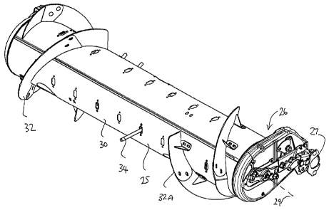
15 The roller 25 as best shown in Figures 4 and 5 comprises a roller
wall
30 which is cylindrical carried for rotation on stub-shafts 31 mounted
suitably on the
arms 26 and connected to end walls of the roller 25 so that the interior of
the roller
has no support at the axis 29 of the shafts 31. On the outside surface of the
roller is
provided an auger flight 32 which is arranged helically around the wall 30 and
its
outer surface 33 so as to project outwardly therefrom. The auger flight, as is
well
known, is arranged in two sections coiled in opposite directions so as to tend
to carry
the crop inwardly toward the center of the feeder house as the roller rotates
in a
CA 02875047 2014-12-15
16
feeding or counter clockwise direction as shown in Figure 4.
In addition the roller carries fingers 34 at angularly and axially spaced
positions around the peripheral surface 33 of the roller. In the embodiment
shown
there are six angularly spaced positions of the fingers and six axially spaced
positions of the fingers. However these numbers may vary in accordance with
requirements.
The fingers rotate with the roller 25 but are driven by an arrangement
described in more detail hereinafter so that they move radially of the axis of
the roller
as the roller angularly advances. Thus in one of the fingers indicated at 34A
provides
a maximum extension of the fingers beyond the surface 33 so that the finger
projects
beyond an outside edge 32A of the flight. This maximum extension position 34A
is
generally at or just above the three o'clock position in Figure 3 or
immediately at the
front of the roller facing the crop. This position may be slightly angularly
advanced or
slightly angularly retarded as required so that for example as shown in Figure
2 with
the roller in its lowered position close down onto the pan 23 the most
extended
position is approximately at the 8.30 position around the axis of the roller.
Symmetrically the most retracted position of the fingers is indicated at
34B which is located directly behind the roller. Thus the normal operation of
the
roller and the fingers carried thereby is that the fingers extend to their
maximum
extension in front of the rollers so as to grasp the crop in front of the
roller and
tending to pile in front of the roller and to push that crop downwardly and to
carry it
rearwardly in a feeding action over the pan 23 to the feeder house. Behind the
roller
CA 02875047 2014-12-15
17
the fingers gradually retract to the position indicated at 34B where the outer
end of
the finger is substantially flush with the surface 33 so as to ensure that the
crop is
released at this position and is not carried by the fingers in a wrapping
action around
the remainder of the roller.
The above description relates to conventional constructions which are
well known for providing a feeding action.
Turning now to the drive arrangement for the fingers of the roller as
shown in Figures 3, 4, 5 and 6, the roller 25 has an outer peripheral wall 33
of the
roller which rotates as described above and contains a plurality of finger
units 40
mounted within the roller 25 arranged to provide a plurality of fingers 34C,
34D
projecting outwardly of the peripheral wail for engaging crop outside the
peripheral
wall 33.
Each finger unit includes a center inner member 41 carrying the pair of
fingers 34C and 34D which are co-linear and lie on a diameter of the axis 29
of the
roller. The roller has in the peripheral wall 33 thereof a plurality of pairs
of finger
guide holes 42, 43 spaced axially of the roller with each pair disposed on
opposite
sides of the roller on the diameter defined by the fingers 34C, 34D. Each pair
of
finger guide holes includes a tubular bushing 42A, 43A such that each of the
pair of
fingers extends through and is slidable in a respective one of the pair of
holes in
opposite sides of the roller so as to be movable along its length from a
retracted
position in which an end of the finger is adjacent the peripheral wall to an
extended
position on the finger path.
CA 02875047 2014-12-15
18
Each finger unit includes a respective inner member 41 within the roller
to which the pair of fingers are affixed so that movement of the inner member
41
acts to drive the fingers to the retracted and extended positions. Each inner
member
41 is formed in two portions 41A, 41B which are identical and arranged back to
back
and connected by bolts 40C at top and bottom. Each portion has a bore 40D into
which a respective one of the fingers 34B, 34C is inserted and attached by
fasteners
40E to hold the fingers co-linear and extending outwardly from the outer face
of the
portions.
In order to drive the fingers to the retracted and extended positions, the
inner member 41 defines an internal continuous elongate guide slot 44 which
cooperates with a stationary guide member 45 inside the roller arranged to
cause
the inner member 41 with the fingers of each of the finger units to
reciprocate during
the rotation of the roller. The stationary guide member is mounted on a common
shaft with a plurality of similar guide members each associated with a
respective
inner member arranged along the length of the roller.
The guide slot extends generally transverse to the axis of the roller and
generally transverse to the longitudinal direction of movement of the fingers.
The
stationary guide member 45 is offset from the center 29 of the roller so that
the
rotation of the inner member 41 with the roller causes the stationary guide
member
45 to slide along the slot 44 which forces the inner member 41 to follow a
path
defined by the slot 44. Thus the guide slot 44 defined by the inner member 41
lies in
a radial plane of the axis of the roller and the fingers 34C, 34D lie on a
diameter of
CA 02875047 2014-12-15
19
the roller with the guide holes 42, 43 being diametrically opposed thus
generating a
predetermined movement of the inner member and the fingers carried thereby.
Instead of being straight and transversely across the line defined by
the fingers, the guide slot 44 of the inner member is generally S-shaped so as
to
comprises a center portion 44A transverse to the longitudinal direction of
movement
of the fingers and a first lobe portion 44B at a first end of the center
portion diverging
to a first side of the center portion and a second lobe portion 44C at a
second end of
the center portion diverging to a second side of the center portion.
This S-shape of the slot generates a path of the ends 34A and 34B of
the fingers which is particularly advantageous and is shown in Figure 3. Thus
the S-
shape of the guide slot causes the finger ends to follow a path S1 which is
different
from the generally circular path S2 of the conventional drive arrangements.
This
path has lobes S11, S12 and S13 of maximum extension of the fingers where the
path is outside the conventional path S2. The path S1 however has a minimum
projection of the finger at the same position directly behind the roller at
34B. Thus
the important action of the finger at or just above the 3 o'clock position in
Figure 3 is
increased by the increased extent of the finger at this location relative to
the path S2.
The finger then remains extended outside the path S2 until it is required to
be
retracted at the 9 o'clock position shown at 34B.
As shown in cross-section in Figure 6, the stationary guide member 45
includes a roller running in the guide slot 44 and the guide slot and the
roller are
correspondingly V-shaped in cross-section with the roller having a V-shaped
recess
CA 02875047 2014-12-15
45R to receive a projecting apex 44R on the wall of the slot 44 so as to
maintain the
guide roller tracking in the guide slot.
Also in this arrangement, the fixed guide 145 has been adjusted
relative to the diameter of the roller so that it lies on or closer to the
diameter
5 containing the fingers 34C and 34D. This acts to change the finger pattern
by
moving the lobes S11, S12 and 813.
As shown in Figure 4A at arrow X, the fixed guide roller 145 is moved
in an arc around the axis 29 of the drum to adjust finger "timing" as
indicated at
arrow T, that is the point of maximum finger projection relative to a fixed
point in
10 space.
As shown in Figure 4B at arrow Y, in order to reverse the finger pattern
for use in reversing the roller during an unblocking process, the guide roller
145 is
moved from its position in Figure 4 to a position to the rear of the feed
drum.
As shown in Figure 4C at arrow Z, the S-shaped track can be rotated
15 about the axis A of the guide roller with respect to the finger to alter
the finger
pattern.
The S shaped track as shown in Figure 3 formed of two smooth
interconnecting curves with no straight parallel sections is the preferred
design. The
S shape is perpendicular to the finger at the point where it crosses the
finger, and
20 the radius of the smooth curves of the S shape is arranged to be of
the same order
of magnitude a or slightly larger than the distance between the 'center 29 of
the drum
and the axis of the control roller 45. This radius is necessary to lower the
control
CA 02875047 2014-12-15
21
loads due to the inertia of the finger system, as well as to maximize the
dwell given
the constraints of the swept diameter and drum size. Also as shown in Figure
4C,
the curvature of the S-shape is reduced so that a divergence to one side of a
straight
line L through the axis A is reduced relative to previous embodiments. The S-
shape
may or may not have straight lines parallel to the line L at the axis A or may
be
formed from two interconnecting smooth curves.
In Figure 7 is shown the pattern generated by a C-shaped track 148
which is two smooth curves 149, 150 joining at the center axis A with little
or no
straight section but where the curves are on the same side of the guide roller
145.
This provides as shown up to 1800 of dwell, the largest swept area and a
finger
pattern which is not symmetrical.