Note: Descriptions are shown in the official language in which they were submitted.
CA 02875383 2014-12-17
DEVICE AND SYSTEM FOR LIFTING A MOTOR VEHICLE
Field of the Invention
The present invention relates to devices and systems for lifting a motor
vehicle, such a bus, to facilitate maintenance or service operations on the
motor
vehicle.
Background of the Invention
Hydraulically-powered lifts are commonly used at maintenance facilities and
service stations to lift buses, trucks, automobiles, and other types of motor
vehicles.
Lifting a motor vehicle is often necessary when performing service or
maintenance
CA 02875383 2014-12-17
2
operations such as tire or brake replacement, or tasks that require access to
the
underside of the motor vehicle.
Conventional hydraulic lifts typically comprise a hydraulic cylinder. The
hydraulic cylinder includes a casing, and piston telescopically disposed
within the
casing. Pressurized hydraulic fluid is directed into the casing, so that the
fluid acts
against a first end of the piston. The force of the fluid on the piston causes
the piston
to extend from the casing. A superstructure suitable for engaging the motor
vehicle
can be mounted on the opposing end of the piston, so that extension of the
piston from
the casing urges the superstructure into the motor vehicle, and thereby lifts
the motor
vehicle.
The casing is typically located below the surface of the floor of the shop or
service area, so that the piston can be retracted so as to place the
superstructure at or
near floor level when the vehicle. Positioning the superstructure in this
manner is
necessary to permit the motor vehicle to be driven or otherwise positioned
over the
superstructure. Thus, most or all of the casing must often be located at or
below floor
level. A relatively deep, e.g., ten-foot deep, trench or hole therefore may be
required
to accommodate the casing. The need for a relatively deep trench or hole can
increase
the cost and complexity of the installation, and can make it difficult or
unfeasible to
install a hydraulically-powdered lift in certain locations, e.g., where the
water table or
bedrock level is relatively shallow. Moreover, the structure required to
support the
casing is usually fixed and cast in concrete, with reinforcing bars, further
adding to
the cost and complexity associated with installing and removing the lift.
The amount of hydraulic fluid needed to operate the above-described lift can
be relatively high, e.g., ninety gallons or more. The need to route relatively
large
amounts of pressurized hydraulic fluid through an underground casing generatcs
a
CA 02875383 2014-12-17
3
potential for contamination of the surrounding.area caused by leakage of the
hydraulic
fluid. Moreover, the risk of ground contamination can be relatively high in
applications wherein the unit that pressurizes and controls the flow of the
hydraulic
fluid is located within the trench or hole that accommodates the cylinder.
Summary of the Invention
A preferred embodiment of a system comprises a lifting device for lifting a
Motor vehicle, a support structure for mounting the lifting device in a pit,
and a
carriage for supporting the lifting device from the support structure and
being
movable within the support structure. The system also comprises a cover
coupled to
opposite sides of the carriage so that the cover extends away from the
carriage and
continuously between the opposite sides of the carriage.
A preferred method for lifting a motor vehicle comprises positioning the
motor vehicle so that a first axle of the motor vehicle is located directly
above a first
scissors lift located in a first pit, and a second axle of the motor vehicle
is located over
a second pit having a second scissors lift located therein. The method also
comprises
positioning the second scissors lift so that the second scissors lift is
located directly
beneath the second axle, and extending the first and second scissors lifts so
that the
first and second scissors lifts urge the respective first and second axles
upward.
A preferred embodiment of a kit comprises a support structure capable of
being installed in a pit so that a lower surface of the support structure
rests on a floor
of the pit, and fasteners for securing the support structure in place within
the pit. The
kit also comprises a scissors lift capable of being mounted on the support
structure so
that the scissors lift can move between an extended position wherein a portion
of the
scissors lift is extends from the support structure, and a retracted position
wherein a
substantial entirety of the scissors lift is located within the support
structure.
CA 02875383 2014-12-17
4
A preferred embodiment of a lifting device comprises a base, a first leg
pivotably coupled to the base, a first leg leaf pivotally coupled to the base
and the first
leg, a bolster, and a second leg pivotally coupled to the bolster. The lifting
device
also comprise a second leg leaf pivotally coupled to the bolster and the
second leg,
wherein the second leg is coupled to one of the first leg and the first leg
leaf, and the
second leg leaf is coupled to the other of the first leg and the first leg
leaf so that
pivotal movement of the first leg in relation to the first leg leaf and
pivotal movement
of the second leg in relation to the second leg leaf causes the bolster to
rise and lower
in relation to the base, and a mating assembly mounted on the bolster for
engaging an
axle of a motor vehicle.
A preferred embodiment of a vehicle lift comprises a base, and a first tier
comprising a first weldment, and two first leg leaves pivotally coupled to the
first
weldment. The first weldment and the first leg leaves are pivotally coupled to
the
base. The lifting device also comprises a second tier comprising a second
weldment
pivotally coupled to the first leg leaves, and two second leg leaves pivotally
coupled
to the first and second weldments.
The lifting device further comprises a third tier comprising a third weldment
pivotally coupled to the second leg leaves, and two third leg leaves pivotally
coupled
to the second and third weldments. The lifting device also comprisesa bolster
pivotally coupled to the third weldment and thc third leg leaves, and a mating
adapter
capable of engaging an axle of a motor vehicle so that the vehicle lift can
lift the
motor vehicle by way of the axle.
Brief Description of the Drawings
The foregoing summary, as well as the following detailed description of a
preferred embodiment, are better understood when read in conjunction with the
CA 02875383 2014-12-17
appended diagrammatic drawings. Forthe purpose of illustrating the invention,
the
drawings show an embodiment that is presently preferred. The invention is not
limited, however, to the specific instrumentalities disclosed in the drawings.
In the
drawings:
Fig. 1 is a perspective view of preferred embodiment of a lifting device,
depicting the lifting device in an extended position;
Fig. 2 is an exploded perspective view of the lifting device shown in Fig. 1;
Figs. 3A-3C are front (or rear), side, and perspective views, respectively, of
the lifting device shown in Figs. 1 and 2, depicting the lifting device in a
retracted
position;
Fig. 3D is a cross-sectional view of the lifting device shown in Figs. 1-3C,
taken through the line "A-A" of Fig. 3B;
Fig. 4 is a front (or rear) view of the lifting device shown in Figs. 1-3D,
=
depicting the lifting device in its retracted position;
Figs. 5A-5C are front (or rear), side, and perspective views, respectively, of
the lifting device shown in Figs. 1-4, depicting the lifting device in its
extended
position;
Fig. 5D is a cross-sectional view of the lifting device shown in Figs. 1-5C,
taken through the line "A-A" of Fig. 5B;
Fig. 6 is a front (or rear) view of the lifting device shown in Figs. 1-5D,
depicting the lifting device in its extended position;
Fig. 7A is a perspective view of a base of the lifting device shown in Figs. 1-
6;
Fig. 7B is a perspective view of an alternative embodiment of a gusset of the
base shown in Fig. 7A;
CA 02875383 2014-12-17
6
Fig. 8 is a perspective view of an inner, leg weldment of a first tier of the
lifting device shown in Figs. 1-7;
Fig. 9 is a perspective view of an inner leg weldment of a second tier of the
lifting device shown in Figs. 1-8;
Fig. 10 is a perspective view of an inner leg weldment of a third tier of the
lifting device shown in Figs. 1-9;
Fig. 11 is a perspective view of reinforcing plates and a gusset of the inner
leg
weldment shown in Fig. 10;
Fig. 12 is a perspective view of a centering link of the lifting device shown
in
Figs. 1-11;
Fig. 13 is a perspective view of a locking mechanism of the lifting device
shown in Figs. 1-12, with an upper lock assembly of the locking mechanism in a
locked position;
Fig. 14 is an exploded perspective view of the locking mechanism shown in
Fig. 13;
Fig. 15 is an exploded perspective view of a lock actuator and control
assembly of the locking mechanism shown in Figs. 13 and 14;
Fig. 16 is a front view of an installation incorporating two of the lifting
devices shown in Figs. 1-15, depicting one of the lifting devices in a front
pit, with the
lifting device in its extended position and lifting a bus;
Fig. 17 is a rear view of the installation shown in Fig. 16, depicting the
other
of the lifting devices installed in a rear pit of the installation, and
showing the lifting
device in its extended position and lifting the bus;
Fig. 18 is a side view of the installation shown in Figs. 16 and 17, and
depicting further details of the installation, including a support structure
and carriage
CA 02875383 2014-12-17
7
assembly for mounting the lifting device in the front pit, and a cover for the
support
structure;
Fig. 19 is a side view of an installation incorporating two conventional
lifting
devices of comparable capacity to the lifting devices shown in Figs. 1-6 and
16-18;
Fig. 20 is a front view of the front pit, lifting device, support structure,
cover,
and carriage shown in Figs. 16 and 18, depicting the lifting device in its
retracted
position;
Figs. 2IA and 21B are side views of two cover elements of the cover shown in
Fig. 20, depicting the manner in which the cover elements can articulate with
respect
to each other;
Fig. 22 is a perspective view of the lifting device, carriage, and cover shown
in
Figs. 16, 18, and 20-2IB;
Fig. 23 is a perspective view of the front pit, lifting device, carriage, and
support shown in Figs. 16, 18, and 20, with the cover removed;
Fig. 24 is a perspective view of the carriage shown in Figs. 18, 22, and 23;
Fig. 25 is a perspective view of a base of the lifting device shown in Figs.
16,
18, 20, 22, and 23;
Fig. 26 is a perspective view of the lifting device, carriage, and base shown
in
Figs. 16, 18, 20, and 22-25, showing the lifting device in its retracted
position;
Fig. 27 is a front view of the lifting device, carriage, and base shown in
Figs.
16, 18, 20, and 22-26, showing the lifting device in its extended position;
Fig. 28 is a front view of a side panel of the support structure shown in
Figs.
18, 20, and 23;
Fig. 29 is a perspective view of a mating assembly of the lifting device shown
in Figs. 1-15;
CA 02875383 2014-12-17
8
Fig. 30 is a front view of the mating assembly shown in Fig. 29;
Fig. 31 is a perspective view of a base adapter of the mating assembly shown
in Figs. 29 and 30;
=
Fig. 32 includes perspective views of various risers of the mating assembly
shown in Figs. 29-31;
Fig. 33 includes perspective views of various accessory adapters of the mating
assembly shown in Figs. 29-32;
Figs. 34A-F depict a lifting device of the type shown in Figs. 1-6, configured
for use with a platform for accommodating a vehicle;
Figs. 35A-D depict two lifting devices of the type shown in Figs. 1-6,
configured for use with another type of platform for accommodating a vehicle;
Figs. 36A-F depict four lifting devices of the type shown in Figs. 1-6,
configured for use with another type of platform for accommodating a vehicle;
Figs. 37A-D depict a lifting device of the type shown in Figs. 1-6, configured
for use with swing arms for accommodating a vehicle; and
Figs. 38A-D depict two lifting devices of the type shown in Figs. 1-6,
configured for use with swing arms for accommodating a vehicle.
Detailed Description of Preferred Embodiments
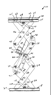
Figures 1-15 depict a preferred embodiment of a lifting device 10 in the form
of a scissors jack, and various components thereof. The lifting device 10 can
be used
to lift a vehicle such as a bus 200, as shown in Figures 16-18. The lifting
device 10 is
believed to be particularly well suited for lifting relatively heavy vehicles
such as the
bus 200, due to the relatively high lifting capacity and relatively small size
of the
lifting device 10.
CA 02875383 2014-12-17
9
The lifting device 10 can move between an extended position (Figures 1 and
5A-6) and a retracted (collapsed) position (Figures 3A-4). The lifting device
10
comprises a first (bottom) tier 12, a second (intermediate) tier 14, and a
third (upper)
tier 16 (see Figure 1). The lifting device also comprises a base 18 and a
bolster 20.
The base 18 comprises a base plate 21, and two substantially C-shaped
channels 24 secured to the base plate 21 by a suitable means such as welding.
The
base plate 21 can be formed from 3/4-inch thick A36 mild steel, or other
suitable
materials. It should be noted that the optimal value for the thickness of the
base plate
21 is application-dependent, and can vary with factors such as the maximum
lifting
capacity of the device 10. A specific value for the thickness is presented for
exemplary purposes only.
Gussets 27 can be secured to the channels 24 and the base plate 21 by a
suitable means such as welding, to help stiffen the channels 24. (An
alternative
versions of the gussets 27, in the from of a gusset 27a, is depicted in Figure
78.) The
base plate 21 preferably has a cutout 29 formed therein to accommodate lines
(not
shown) that route hydraulic fluid to and from a hydraulic actuator 62 of the
device 10.
The bolster 20 comprises a base plate 150, and two substantially C-shaped
channels 54 secured to a lower surface of the base plate 150 by a suitable
means such
as welding. The base plate 150 can be formed from one-inch thick A514 (T1)
high
strength steel, or other suitable materials. It should be noted that the
optimal value for
the thickness of the base plate 150 is application-dependent, and can vary
with factors
such as the maximum lifting capacity of the device 10. A specific value for
the
thickness is presented for exemplary purposes only.
Three gussets (not shown) preferably are secured each of the channels 54 and
the base plate 150 to help stiffen the channels 54 (the gussets 152 are shown
in
CA 02875383 2014-12-17
phantom, in Figure 3C). The bolster 20.also includes two T-shaped members 154,
two retaining plates 156, and a stop 158 each secured to an upper surface of
the base
plate 150 by a suitable means such as welding. The bolster 20, as discussed
below,
accommodates a mating assembly 170 that acts as an interface between the
device 10,
and the bus 200 or other vehicle being lifted by the device 10.
The first tier 12 comprises an inner leg weldment 22. The inner leg weldment
22 comprises two legs 28, and plates, or cross-members 129 secured to each of
the
legs 28 by a suitable means such as welding. The legs 28 and cross-members 129
can
be formed from, for example, A36 mild steel or other suitable materials. (The
other
structural components of the device 10 can be formed from A36 mild steel or
other
suitable materials, unless otherwise noted.) One of the cross-members 129
preferably
has a cutout 130 formed therein to accommodate flexing of the hydraulic lines
that
route hydraulic fluid to and from the hydraulic actuator 62.
The inner leg weldment 22 is pivotally coupled to the base 18, i.e., the inner
leg weldment 22 is coupled to the base 18 so that the inner leg weldment 22
can pivot
in relation to the base 18. More specifically, a first end of each leg 28 of
the inner leg
weldment 22 can be pivotally to the base 18 by a pair of bearings in the form
of slider
blocks 23, and a pin 125 secured to each of the legs 28 (see Figures I, 2, and
7).
Preferably, the pin 125 is secured to each of the legs 28 by welds formed
between the
pin 125, and both the inwardly and outwardly facing sides of each leg 28.
Each slider block 23 slides within a corresponding one of the channels 24 as
the device 10 moves between its extended and retracted positions. The slider
blocks
23 preferably are formed from a material that helps to minimize sliding
friction, such
as NYLATRON, ultra-high molecular weight polyurethane, or other suitable
materials.
CA 02875383 2014-12-17
11
The first tier 12 also comprises two outer leg leaves 26. A first end of each
outer leg leaf 26 is pivotally coupled to the base 18 by another pair of
slider blocks 23
each slidably disposed within a corresponding channel 24, and a pin 25 that
extends
through each of the outer leg leaves 26. The outer leg leaves 26 can be
connected by
a cross member (not shown) secured to the outer leg leaves 26 by a suitable
means
such-as fasteners, to provide the outer leg leaves 26 with additional lateral
stiffness.
Each outer leg leaf 26 preferably is undercut proximate the first end thereof,
as shown
in Figure 2, to facilitate clearance between the outer leg leaf 26 and the
base plate 21
of the base 18.
A bearing in the form of a sleeve 31 preferably is disposed on both the pin
125
and the pin 25 (see Figure 2; the sleeves 31 are not depicted in Figure 8, for
clarity).
The sleeves 31 contact the base plate 21 of the base 18, and thereby increase
the load-
bearing area on the pins 125, 25. The sleeves 31 preferably are formed from a
material that helps to minimize sliding friction, such as ultra-high molecular
weight
polyurethane, NYLATRON, or other suitable materials.
One of the outer leg leaves 26 is pivotally coupled to a corresponding leg 28
of the inner leg weldment 22, by a suitable means such as a pin 30 attached to
the leg
28, and a journal bearing 134 and washer 136 (see Figures 1 and 2). The
journal
bearing 134 can be, for example, a POLYLUBE composite bearing, available from
Polygon Co. of Walkerton, Indiana.
The pin 30 and the journal bearing 134 preferably are accommodated by a
counterbore formed in the leg 28. The pin 30 preferably is positioned
proximate a
midpoint of the leg 28, and engages the outer leg leaf 26 by way of a hole 32
formed
in the outer leg leaf 26, proximate a mid-point thereof. The other outer leg
leaf 26 is
pivotally coupled to the other leg 28 of the inner leg weldment 22 in a
similar manner.
CA 02875383 2014-12-17
12
The second tier 14 comprises an inner leg weldment 36. The inner leg
weldment 36 includes two legs 42, and plates, or cross-members 43 secured to
each of
the legs 42 by a suitable means such as welding. A first end of each leg 42 is
pivotally coupled to a second end of a corresponding outer leg leaf 26 of the
first tier,
by a suitable means such as a pin 38 secured to each of the legs 42, and two
end cap
assemblies 132 (see Figures 1, 2, and 8). Preferably, the pin 38 is secured to
each of
the legs 42 by welds formed between the pin 38, and both the inwardly and
outwardly
facing sides of each leg 42.
Each end cap assembly 132 preferably comprises one of the journal bearings
134, one of the washers 136, a pin 140, a pin retainer cap 142, and a fastener
144 that
securely engages the pin 38.
The second tier 14 also comprises two outer leg leaves 40. A first end of each
outer leg leaf 40 is pivotally coupled to a second end of a corresponding leg
28 of the
inner leg weldment 22. The outer leg leaves 40 and the legs 28 can be coupled
by a
suitable means such as a pin 39 secured to the legs 28, and two end cap
assemblies
132. Preferably, the pin 38 is secured to each of the legs 28 by welds formed
between
the pin 39, and both the inwardly and outwardly facing sides of each leg 28.
The pin
39 preferably has a cutout 41 formed therein to provide clearance between the
pin 39
and the hydraulic actuator 62 of the device 10, as the device 10 moves between
its
retracted and extended positions.
One of the outer leg leaves 40 is pivotally coupled to a leg 42 of the inner
leg
weldment 36 by a suitable means such as a pin 44 attached to the leg 42, and
another
of the journal bearings 134 and washers 136. The pin 44 and the journal
bearing 134
preferably are accommodated by a counterbore formed in the leg 42. The pin 44
preferably is positioned proximate a midpoint of the leg 42, and engages the
outer leg
CA 02875383 2014-12-17
13
leaf 40 by way of a hole 46 formed in the leaf 40 proximate a mid-point
thereof. The
other of the outer leg leaves 40 is pivotally coupled to another leg 42 of the
inner leg
weldment 36 in a similar manner.
The third tier 16 comprises an inner leg weldment 48. The inner leg weldment
48 includes two legs 55, and plates, or cross-members 57 secured to each of
the legs
55 by a suitable means such as welding. Each leg 55 is pivotally coupled to a
second
end of a corresponding leaf 40 of the second tier, by a pin 50 secured to each
of the
legs 55, and two of the end cap assemblies 132. Preferably, the pin 50 is
secured to
the legs 55 by welds formed between the pin 50, and both the inwardly and
outwardly
facing sides of each leg 55.
The third tier 16 also comprises two outer leg leaves 52. Each of the outer
leg
leaves 52 is pivotally coupled to a second end of a corresponding leg 42 of
the inner
leg weldment 36 by a pin 49 secured to the legs 42, and two of the end cap
assemblies
132. Preferably, the pin 49 is secured to each of the legs 42 by welds formed
between
the pin 49, and both the inwardly and outwardly facing sides of each leg 42.
Each
outer leg leaf 52 preferably is undercut proximate an end thereof, as shown in
Figure
2, to facilitate clearance between the outer leg leaf 52 and the base plate
150 of the
bolster 20.
A second end of each leg 55 of the weldment 48 is pivotally coupled to the
bolster 20 by another pair of the slider blocks 23, and a pin 51 secured to
the legs 55
(see Figures 1, 5C, and 6). Preferably, the pin 51 is secured to each of the
legs 55 by
welds formed between the pin 51, and both the inwardly and outwardly facing
sidcs
of each leg 55. Each slider block 23 is located within a corresponding one of
the
channels 54 of the bolster 20, and slides within the channel 54 as the device
10 moves
between its extended and retracted positions.
CA 02875383 2014-12-17
14
A second end of each outer leg leaf 52 is pivotally coupled to the bolster 20
by
another pair of the slider blocks 23 each disposed within an associated one of
the
channels 54, and another of the pins 25. The slider blocks 23 slide within
their
associated channel 54 as the device 10 moves between its extended and
retracted
positions.
Another pair of the sleeves 31 preferably is disposed on both the pin 51, and
the pin 25 associated with the outer leg leaves 52. The sleeves 31 contact the
base
plate 150 of the bolster 20, and thereby increase the load-bearing area on the
pins 51,
25.
One of the outer leg leaves 52 is pivotally coupled to a leg 55 of the inner
leg
weldment 48 by a suitable means such as a pin 56 attached to the leg 55, and
another
journal bearing 134 and washer 136. The pin 56 and the journal bearing 134
=
preferably are accommodated by a counterbore formed in the leg 55. The pin 56
is
preferably positioned proximate a midpoint of the leg 55, and engages the
outer leg
leaf 52 by way of a hole 58 formed in the outer leg leaf 52 proximate a mid-
point
thereof. The other of the outer leg leaves 52 is pivotally coupled to another
leg 55 of
the inner leg weldment 48 in a similar manner.
The pins 25, 30, 38, 39, 42, 49, 51, 55, 125 can be formed from 4140
casehardened steel, or other suitable materials. The pins 25, 30, 38, 39, 42,
49, 51, 55,
125 can each have a diameter of approximately two inches. It should be noted
that
the optimal diameter for these pins is application-dependent, and can vary
with factors
such as the maximum lifting capacity of the device 10. A specific value for
the
diameter is presented for exemplary purposes only.
The lifting device 10 is depicted with three tiers for exemplary purposes
only.
The optimal number of tiers is application dependent, and can vary with
factors such
CA 02875383 2014-12-17
as the desired lifting capacity of the lifting device 10, and the desired
height of the
lifting device 10 above the shop floor when the lifting device 10 is in its
extended
position.
The hydraulic actuator 62 actuates the lifting device 10 between its extended
and retracted positions (see Figures 2, 4, 5B, 5C, and 14). The hydraulic
actuator 62
includes a cylinder 66, and a rod 68 that retracts and extends into and out of
the
cylinder 66. An end of the rod 68 is pivotally coupled to the legs 55 of the
weldment
48, proximate the first end of the weldment 48, by a suitable means such as a
pin 70.
The pin 70 can be formed, for example, from heat-treated 4140 steel or other
suitable
materials. The pin 70 can be equipped with drilled and tapped holes to
accommodate
a slide puller during disassembly of the device 10.
An end of the cylinder 66 is pivotally coupled to the legs 28 of the weldment
22, proximate the first end of the weldmcnt 22, by a suitable means such as a
pin 71. =
The cylinder 66 can include a pin-retaining member 67 for receiving the pin 71
(see
Figure 14). The member 67 can be split, as depicted in Figure 14, so that a
first half
67a of the member 67 can be removed from the remainder of the cylinder 66. The
first half 67a can be secured to the remainder of the member 67 by four bolts
(not
shown). This feature can facilitate removal and installation of the cylinder
66 without
need to disassemble or otherwise remove any of the components of the first
tier of the
device 10.
It should be noted that other types of actuators can be used in lieu of the
hydraulic actuator 62 in alternative embodiments.
The pin 71 can be accommodated by through holes forrned in the legs 28 of
the inner leg weldment 22 (see Figure 8). Bolts 73 can be used to secure the
pin 71
from rotational and axial movement in relation to the legs 28. The bolts '73
can
CA 02875383 2014-12-17
16
extend upward through taps 75 formed in the legs 28, and can threadably engage
an
upper portion (not shown) of the corresponding tap 75, i.e., a portion of the
tap 75
located above the corresponding through hole.
The weldment 48 includes mounting plates 72, and a gusset 74 secured to. an
inwardly-facing surface of each leg 55 thereof (see Figure 10 and 11). The
mounting
plates 72 and the gusset 74 provide the weldment 48 with additional strength
to
withstand the loads that the hydraulic actuator 62 exerts thereon.
The cylinder 66 preferably is a doublc-acting cylinder. The cylinder 66 is in
fluid communication, on a selective basis, with a tank of hydraulic fluid
located
within a free-standing control console (not shown). The hydsaulic fluid is
pressurized
by a pump (not shown), and acts on a piston (not shown) within the cylinder 66
so as
to cause the piston to translate within the cylinder 66. Movement of the
piston
imparts a corresponding movement to the rod 68 that causes the rod 68 to
extend from
or retract into the cylinder 66. The flow of hydraulic fluid to the cylinder
66 (and the
resulting movement of the rod 68) is controlled by way of the control console.
The control console can also include, for example, a hydraulic pump, a
hydraulic manifold and valving, a starter motor, thermal overloads, a
programmable
logic controller, and operator interface push buttons.
The piston of thc hydraulic actuator 62 preferably has a stroke of
approximately twenty-one inches, and the cylinder 66 preferably has a bore of
approximately seven inches. The hydraulic fluid is preferably supplied to the
hydraulic actuator 62 at a pressure of approximately 3,500 psi when the
lifting device
is being extended, and at a pressure of approximately 500 psi when the lifting
device 10 is being retracted. The hydraulic actuator 62 requires approximately
3.5
gallons of hydraulic fluid. 11 should be noted that the stroke, bore,
operating
CA 02875383 2014-12-17
17
pressures, and fluid capacity associated with the hydraulic actuator 62 are
application
dependent; specific values for these parameters are specified for exemplary
purposes
only.
The cylinder 66 preferably has a wall thickness of approximately 1/2-inch. The
optimal value for the wall thickness is application-dependent, and can vary
with
factors such as the maximum lifting capacity of the device 10. A specific
value for
the wall thickness is presented for exemplary purposes only.
Retraction and extension of the rod 68 into and out of the cylinder 66 imparts
forces on the weldment 22 and the weldmcnt 48. These forces cause the lifting
device
to move between its retracted and extended positions.
The lifting device 10 further includes a locking mechanism 82 for locking the
lifting device 10 in its extended position, or in a partially-extended
position (see
Figures 3D, 5D, 13, and 14). The locking mechanism 82 includes an upper lock
assembly 84, and two jaw locks 85. The upper lock assembly 84 and the jaw
locks 85
can be formed from A514 (T1) high strength steel, or other suitable materials.
The
jaw locks 85 are secured to mounting provisions 86 formed on the cylinder 66.
An
end of each jaw lock 85 is pivotally coupled to the first end of the weldment
22 by the
pin 71 (the jaw locks 85 therefore pivot with the cylinder 66).
The upper lock assembly 84 is pivotally coupled to the legs 55 of the
weldment 48 by the pin 70. The upper lock assembly 84 has a plurality of teeth
87
formed therein, and the jaw locks 85 each have a plurality of teeth 90 formed
therein.
The upper lock assembly 84 can pivot between a locked position (Figure 5D) in
which
the teeth 87 engage the teeth 90, and an unlocked position (Figure 3D) where
the teeth
87 are disengaged from the teeth 90.
CA 02875383 2014-12-17
18
The locking mechanism 82 prevents the'lifting device 10 from moving toward
its retracted position when the teeth 87 engage the teeth 90 (the lifting
device 10 can
move toward its retracted position when the teeth 87 and the teeth 90 are
disengaged).
The teeth 87 can ride over the teeth 90 as the lifting device 10 moves toward
its
extended position. In other words, the engagement of the teeth 87 and the
teeth 90
does not prohibit extension of the lifting device 10.
The configuration of the upper lock assembly 84 and the jaw locks 85 permits
the lifting device 10 to be locked in various positions (including its fully-
extend
position, and a position approximately twenty-four inches above the floor as
required
by the Automated Lift Institute and ANSI standard, ALCTV 1998).
The locking mechanism 82 also includes a lock actuator and control assembly
88 mounted on the upper lock assembly 84, within a housing 91 (see Figure 15).
The
lock actuator and control assembly 88 causes the upper lock assembly 84 to
pivot
between its locked and unlocked positions. The lock actuator and control
assembly
84 preferably comprises a pneumatic actuator 92 and a pneumatic limit switch
94.
The pneumatic actuator 92 comprises a cylinder 96 securecIto thc housing 91.
The
pneumatic actuator 92 also comprises a shaft 98 that extends from and retracts
into the
cylinder 96.
The pneumatic actuator 92 is in fluid communication with a source of
pressurized air (not shown) on a selective basis. The flow of pressurized air
to the
pneumatic actuator 92 causes the shaft 98 to extend from the cylinder 96.
Extension
of the shaft 98 causes the shaft 98 to contact and exert a force on the
cylinder 66 of
the hydraulic actuator 62 by way of a bumper 100. Further extension of the
shaft 98
causes the shaft 98 to lift the upper lock assembly 84 toward its unlocked
position
(interrupting the flow of pressurized air to the pneumatic actuator 92 causes
the shaft
CA 02875383 2014-12-17
19
98 to retract into the cylinder 96, thereby causing the upper lock assembly 84
to return
to its locked position).
The flow of pressurized air to the pneumatic actuator 92 is controlled from
the
control console. The pneumatic limit switch 94 contacts the cylinder 66 of the
hydraulic actuator 62 so that the pneumatic limit switch 94 receives a
mechanical
input indicating the position of the pneumatic actuator 92 (and the upper lock
assembly 84). The pneumatic limit switch 94 sends a pneumatic signal to the
control
console indicating the position of the upper lock assembly 84.
The lifting device 10 preferably comprises a centering mechanism. The
centering mechanism causes the lifting device 10 to extend and retract in a
substantially vertical direction, without substantial movement in the lateral
direction.
In other words, the centering mechanism causes the bolster 20 to remain
substantially
centered in relation to the base 18 as the lifting device 10 moves between its
retracted -
and extended positions. The feature causes the load on the lifting device 10
to remain
substantially centered on the lifting device 10, and can thereby enhance the
stability of
the lifting device 10.
The centering mechanism comprises a first centering link 102 and a second
centering link 104 (see Figures 1 and 2). An end of the first centering link
102 is
pivotally coupled to one of the outer leg leaves 26, between the mid-point and
the first
end thereof, by a 1/2-inch diameter bolt 105 (see Figure 12). It should be
noted that the
optimal diameter of the bolt 105 is application-dependent, and can vary with
factors
such as the maximum lifting capacity of the device 10. A specific value for
this
parameter is disclosed for exemplary purposes only.
The other end of the first centering link 102 is pivotally coupled to a
mounting
provision 108 formed on the base 18, by way of a pin 103. An end of the second
CA 02875383 2014-12-17
centering link 104 is pivotally coupled to. the other of the outer leg leaves
26, between
the mid-point and the first end thereof, by another bolt 105. The other end of
the
second centering link 104 is pivotally coupled to another of the mounting
provisions
108 formed on the base 18, by another bolt pin 103.
The bolt 105 that joins the first centering link 102 and the associated outer
leg
leaf 26 preferably is accommodated by a slot formed in the first centering
link 102
(the slot is shown in phantom in Figure 12). The other bolts 105 preferably
are
accommodated by substantially circular holes the second centering link 104.
The use
of the slot in the first centering link 102 can help to facilitate insertion
of thc
associated bolt 105 in the first leg leaf 26, when the first leg leaf 26 and
the first
centering link 102 arc misaligned due to the stack-up of manufacturing
tolerances of
the various components of the device 10.
The centering mechanism further comprises a third centering link 110 and a
fourth centering link 112. An end of the third centering link 110 is pivotally
coupled
to one of the outer leg leaves 52 of the third tier 16, between the mid-point
and the
first end thereof, by another bolt 105. The other end of the third centering
link 110 is
pivotally coupled to a mounting provision 114 formed on the bolster 20,
between the
mid-point and the first end thereof, by another pin 103. An end of the fourth
centering link 112 is pivotally coupled to the other of the outer leg leaves
52 of the
third tier 16, by another bolt 105. The other end of the fourth centering link
112 is
pivotally coupled to another of the mounting provisions 114 formed on the
bolster 20,
by another pin 103.
The bolt 105 that joins the third centering link 110 and the associated outer
leg
leaf 26 preferably is accommodated by a slot formed in the third centering
link 110.
CA 02875383 2014-12-17
21
The other bolt 105 preferably is accommodated by a substantially circular hole
formed in the fourth centering link 112.
The bolster 20, as noted above, accommodates the mating assembly 170 that
acts as an interface between the device 10, and the bus 200 or other vehicle
being
lifted by the device 10. The mating assembly 170 preferably comprises two base
adapters 172, a plurality of extensions, or risers 173, and a plurality of
accessory
adapters 174 (see Figures 29-33).
The accessory adapters 174 engage the axle of the bus 200 or other vehicle
being lifted by the device 10. The base adapters 172 mate with the bolster 20,
and
permit the mating assembly 170 to be positioned at a desired location on the
bolster
20. The risers 173 allow the height of the accessory adapters 174 in relation
to the
accessory adapters to be adjusted to accommodate a particular type of vehicle.
The base adapters 172 each comprise a plate member 175, and two guides 176
secured to opposite sides of the plate member 175 (see Figure 31). The guides
176
preferably are shaped to fit within one of the T-shaped members 154 of the
bolster 20,
as shown in Figures 31 and 32. Each base adapter 172 also comprises a mating
block
177 secured to the plate member 175 by a suitable means such as welding.
Three relatively large diameter holes 178, and two relatively small diameter
holes 179 are formed in the mating block 177. The large and small diameter
holes
178, 179 are positioned so that each small diameter hole 179 is located
between two
large diameter holes 178.
Each base adapter 172 also comprises two reinforcing plates 192 positioned
between, and secured to the mating block 170 and an associated guide 176, and
a pin
assembly 181. The pin assembly 181 is biased in a downward direction by a
suitable
means such as a spring. Contact between a pin 182 of the pin assembly 181 and
an
CA 02875383 2014-12-17
22
associated one of the retaining plates 156'on the'base plate 150 of the
bolster 20
prevents the base adapter 172 from moving outward and disengaging from the
bolster
20. Inward movement of the base adapter is limited by contact between the pin
182
and the stop 158 on the base plate 150.
The base adapter 172 can be removed from the bolster 20, if desired, by
pulling the pin assembly 181 upward, so that the pin 182 can clear the
associated
retaining plate 156, and pulling the base adapter 172 outward.
The risers 173 allow the height of the accessory adapters 174 in relation to
the
accessory adapters to be adjusted to accommodate a particular type of vehicle,
as
noted above. The risers 173 can have respective heights of, for example,
three, six,
and seven inches (see Figure 32). Each riser 173 preferably includes a
relatively large
diameter projection 183 and a relatively small diameter projection 184 that
each
extend from a lower surface of the riser 173. The large and small diameter
projections 183, 184 are configured to engage the base adapters 172 by way of
the
large and small diameter holes 178, 179 formed therein. The arrangement of the
large
and small diameter holes 178, 179 allows the risers 173 to be placed in one of
four
different positions along the length of the associated accessory adapter 174.
Each riser 173 has a relatively large diameter hole 185, and a relatively
small
diameter hole 186 formed therein. The large and small diameter holes 185, 186
extend inward from an upper surface of the riser 173.
The accessory adapters 174 are configured to engage different types of axles,
to facilitate use of the device 10 with different types of vehicles (see
Figure 33). Each
accessory adapter 174 has a relatively large diameter projection 189, and a
relatively
small diameter projection 190 formed thereon, and extending from a lower
surface
CA 02875383 2014-12-17
=23
thereof. The large and small diameter projections 189, 190 are sized to engage
the
risers 173 by way of the large and small diameter holes 185, 186 formed
therein.
The size and relative locations of the large and small diameter projections
189,
190 on the accessory adapters 174 are substantially identical to the size and
relative
locations of the large and small diameter projections 183, 184 on the risers
173. The
accessory adapters 173 therefore can be used without the risers 173, i.e., the
accessory
adapters 173 can be mounted directly on the base adapters 172.
The ability to position the risers 174 or the accessory adapters 173 in four
different positions on the base adapters 172, and the ability to vary the
position of the
base adapters 172 in relation of the bolster 20 can provide the user with
substantial
flexibility in positioning the accessory adapters 174 at a suitable location
on the axle
of the vehicle being lifted. For example, the spacing between the outer ends
of the
accessory adapters 174 can be varied between a minimum of approximately 24-1/2
inches, and a maximum of approximately 55-1/2 inches (as shown in Figure 31).
(The
maximum and minimum spacing can vary by application; specific values are
presented for exemplary purposes only).
Figures 16-18 depict an exemplary installation for the lifting device 10. In
particular, Figures 16-18 show two of the lifting devices (the forward-located
lifting
device is designated 10a, and the rearward-located lifting device is
designated 10b;
the lifting devices 10a, 10b are substantially identical to the lifting device
10).
The lifting device 10a is located in a front pit 202, and is movable in the
forward of rearward directions, i.e., to the left and right from the
perspective of Figure
18. The lifting device 10b is positioned in a rear pit 204, and is fixed,
i.e., the lifting
device 10b cannot move in the forward and rearward directions.
CA 02875383 2014-12-17
24
The bus 200 has a front axle 208 and a rear axle 210. 'The lifting devices
10a,
10b lift the bus 200 (or other vehicle) by the front and rear axles 208, 210.
In
particular, the bus 200 can be driven over the lifting devices 10a, 10b so
that the rear
axle 210 is positioned directly over the lifting device 10b. The position of
the lifting
device 10a can subsequently be adjusted so that the lifting device 10a is
positioned
directly below the front axle 208. The lifting devices 10a, 10b can then be
extended
so that the mating assembly 170 of each lifting device 10a, 10b contact the
respective
front and rear axles 208, 210 and lift the bus 200. (Extension of the lifting
devices
10a, 10b can be commanded from the control console, as discussed above with
respect to the lifting device 10; the hydraulic lines that supply pressurized
hydraulic
fluid to the hydraulic actuator 62 of each lifting device 10a, 10b are not
depicted in
Figures 16-18, for clarity).
Lifting the bus 200 by the front and rcar axles 208, 210 is particularly well
suited for maintenance or repair operations in which or more of the wheels of
the bus
200 must be removed, as lifting the bus 200 by the front and rear axles 208,
210 is
believed to minimize the height by which the body of bus 200 must be lifted to
break
contact between the wheels and the shop floor. Moreover, lifting the bus 200
by the
axles 208, 210, it is believed, minimizes the obstacles and obstructions
presented by
the lifting equipment to a mechanic or other individual working beneath the
bus 200,
in comparison to other lifting methodologies.
The lifting device 10a is preferably positioned in a carriage 300 (see Figures
23, 24, 26, and 27. The carriage 300 is suspended within a pit box, or support
structure 234 installed in the front pit 202 (see Figure 23). The carriage 300
facilitates
movement of the lifting device 10a within the support structure 234 in the
forward
and rearward directions, so that the lifting device 10a can be aligned with
the front
CA 02875383 2014-12-17
axle 208 of the bus 200. A cover 232 is installed on the support structure
234, and
moves with the carriage 300, as explained below (the cover 232 is not shown in
Figure 23, for clarity).
The support structure 234 preferably comprises two side panels 237, two
bottom flanges 238 that adjoin a corresponding side panel 237, and two end
caps 239
(see Figure 23). The bottom flanges 238 can formed bending the sheet of
material
from which the associated side panel 237 is formed. The end caps 239 are
secured to
opposing ends of the side panels 237 and bottom flanges 238 by a suitable
means such
as fasteners. Each side panel 237 preferably has ribs 241 secured to an
outwardly-
facing surface thcreof, to stiffen and strengthen the side panel 237. One of
more of
the side panels 237 and end caps 239 can be equipped with drain holes 291 to
facilitate drainage of the support structure 234.
An upper support track 290 and a lower support track 292 are secured to one
of the side panels 237 by a suitable means such as fasteners (see Figures 23
and 28).
Another upper support track 290 and lower support track 292 likewise are
secured to
the other of the side panels 237.
A bearing strip 293 can be secured to a top surface of each of the upper and
lower support tracks 290, 292. The bearing strips 293 preferably are formed
from a
material that helps to minimize sliding friction, such as ultra-high molecular
weight
polyurethane, NYLATRON, or other suitable materials.
A gear track 295 is secured to each side panel 237 below the associated upper
support track 290, by a suitable means such as fasteners (see Figure 28).
Two radius end plates 294 are secured to opposing sides of each end cap 239
by a suitable means such as fasteners (see Figure 23). Each radius end plate
294 has a
channel 296 formed therein. The channels 296 can be formed, for example, by
three-
CA 02875383 2014-12-17
26
dimensional milling or other suitable techniqueS. Each channel 296 adjoins an
associated upper and lower support track 290, 292. The depth of each channel
296
preferably varies along a length thereof. The significance of this feature is
discussed
below.
The radius end plates 294 preferably are formed from a material that helps to
minimize sliding friction, such as ultra-high molecular weight polyurethane,
NYLATRON, or other suitable materials.
The support structure 234 is located within the front pit 202. The support
structure 234 preferably is sized so that the bottom flanges 238 rests on the
bottom of
the front pit 202, and minimal clearance exists between the wails of the pit
202, and
the side panels 237 and end caps 239. The side panels 237, end caps 239, and
bottom
flanges 238 can be secured to the walls of the front pit 202 using a suitable
means
such as fasteners. The support structure 234 does not need to be embedded or
cast in
the front pit 202 using concrete and reinforcing bars, or other means. Shims
can be
installed between the support structure 234 and the adjacent surfaces of the
front pit
202 as needed.
The lifting device 10a is suspended within the support structure 234 by the
carriage 300 (see Figures 24, 26, and 27). The carriage 300 comprises two side
plates
302, and two lower support bars 306. Each lower support bar 306 is secured to
a
lower end of a corresponding one of the side plates 302 by a suitable means
such as
welding. Opposing ends 302a of each sidc plate 302 are bent in relation to a
centrally-located portion 302b of the side plate 302, as shown in Figure 26.
This
feature is believed to increase the stiffness of the side plates 302.
The carriage 300 also comprises two upper support bars 308. Each upper
support bar 308 is secured to an upper end of a corresponding one of the side
plates
CA 02875383 2014-12-17
=
27
302 by a suitable means such as welding. The'upper support bars 308 are
connected
by two alignment bars 310, located on opposite sides of the carriage 300. A
strip of
ultra-high molecular weight polyurethane or other suitable material (not
shown) can
be secured to the outwardly-facing surface of each alignment bar 310. These
strips
can contact the associated side panel 237 of the support structure 234, so as
to center
thc carriage 300 within the support structure 234.
The carriage 300 also includes two slides 314. Each slide 314 is secured to
the
underside of an associated upper support bar 308 and alignment bar 310. The
carriage
300 is positioned within the support structure 234 so that the slides 314 rest
on the
bearing strip 293 on an associated one of the upper support tracks 290. The
slides 314
preferably are formed from steel.
The device 10a includes a base 18a (see Figure 25). The base 18a is a
modified version of the base 18 described above. Components of the base 18a
that
are substantially identical to those of the base 18 are denoted by
identical.reference
characters in the figures.
The base 18a includes a plurality of stiffeners 320 secured to a lower surface
of the base plate 21, by a suitable means such as welding. The base 18a also
includes
a plurality of gussets 322 secured to an upper surface of the base plate 21,
outboard of
the channels 24, by a suitable means such as welding. The base 18a further
comprises
two flanges 326 secured to upper surfaces of the gussets 322 by a suitable
means such
as welding. Each flange 326 can be secured to an associated lower support bar
306 of
the carriage, to suspend the device 10a from the carriage 300 as shown in
Figure 26.
The carriage 300 preferably is driven by a hydraulically-powered motor 270,
and a drive gear assembly 272 (see Figure 27). (Other types of drive systems,
including electric motors, can be used in the alternative.) The motor 270 and
the
CA 02875383 2014-12-17
28
drive gear assembly 272 are secured to one of the side plates 302 of the
carriage 300
by a suitable means such as fasteners.
Actuation of the motor 270 is a forward or reverse direction can be controlled
by the user from the control console (Figure 27). Actuation of the motor 270
imparts rotation to
gears 272a of the drive gear assembly 272. The gears 272a engage the teeth
formed
on an associated gear track 295 (Figure 23). The interaction between the gears
272a and the gear
tracks 295 imparts linear movement to the carriage 300 and the device 10a, in
the
longitudinal directions.
The lines that route hydraulic fluid to and from the hydraulic actuator 62 of
the
device 10a preferably are housed, in part, within a carrier 280. A first end
of the
carrier 280 is secured to the carriage 300. A second end of the carrier 280 is
secured
to one of the side panels 237. The carrier 280 preferably is formed from a
plurality of
pivotally connected links that can deflect in a repeatable, predetermined
manner as the
carriage 300 translates, so as to prevent the hydraulic lines from tangling or
otherwise
becoming damaged.
The cover 232 comprises a plurality of beams, or cover elements 240 (see
Figures 21A, 21B, and 22). The cover elements 240 are preferably formed from
extruded 6061 aluminum.
The cover elements 240 each preferably comprise a first major portion 240a, a
second major portion 2406, and first and second side portions 240c, 240d. The
first
and second side portions 240c, 240d adjoin each of the first and second major
portions 240a, 240b, so that the first and second major portions 240a, 240b
and the
first and second side portions 240c, 240d form an isotropic beam.
CA 02875383 2014-12-17
29
The cover elements 240 are supported by the upper and lower tracks 290, 292.
In particular, opposing ends of the major portion 240a of each cover element
240 can
rest on the bearing strips 295 of the associated upper or lower tracks 290,
292.
Each cover element 240 includes mating features that pivotally couple the
cover element 240 to adjacent cover elements 240. For example, each cover
element
240 can include a substantially rod-shaped member 242 the extends from a
leading (or
trialing) end of the first major portion 240, as shown in Figures 21A and 21B.
Each
cover element 240 can have a recess 243 defined therein, proximate the
trailing (or
leading ) end thereof. The recess 243 is shaped to receive and retain the
member 242
of the adjacent cover member 240. Moreover, the configuration of the recess
243
permits the member 242 to rotate about its longitudinal axis within the recess
243.
Movement of the cover 232 in one direction causes the cover elements 240
located to one side of the lifting device 10a to be pushed from the upper
tracks 290 to
the lower tracks 292 by way of the channel 296 in the radius end plates 294
located
proximate one end of the support structure 234. The cover elements 240 located
on
the other side of the lifting device 10a are simultaneously pulled from the
lower tracks
292 to the upper tracks 294 by way of the channels 296 in the radius end
plates 294
located proximate a second end of the support structure 294.
The mating features of the cover elements 240, i.e., the members 242 and the
recesses 243, permit the cover elements 232 to move in a substantially
curvilinear
path along the channels 296 of the radius end plates 294.
The depth of the channels 296 preferably varies along a length thereof, as
noted above. This feature results in a centering force on the cover elements
240 as the
cover elements 240 travel along the channels 296.
CA 02875383 2014-12-17
3)
The cover elements 240 are preferably designed to withstand a 7,500-pound
point load, so that the cover 232 can withstand a drive over by one tire of a
relatively
heavy vehicle such as the bus 200.
The ability of the cover 232 to move with the carriage 300 and the device 10a
permits the lifting device 10a to be lowered to its retracted position (below
the level
of the surrounding floor) regardless of its position within the front pit 202.
A typical
conventional lift, by contrast, can be fully lowered in only one particular
position, due
to the need for cut outs or other means to accommodate the relatively wide
superstructure and relatively narrow pit associated with such a lift. The
ability to
fully retract the lifting device 10 regardless of its position in the pit 202,
it is believed,
makes the lifting device 10 particularly well suited for use with relatively
low-
wheelbase vehicles such as low-floor transit buses.
Two side panels 298, and two end panels 299 can be secured to the support
structure 234 as depicted in Figure 22, to cover gaps between the cover
elements 240
and the shop floor.
The lifting device 10b is depicted as being installed in the rear pit 204
without
a support structure. The lifting device 10b can be installed in a support
structure
tailed to the dimensions of the rear pit 204, in alternative embodiments.
Figures 34A-34F depict another type of installation incorporating the lifting
device 10. In particular, Figures 34A-34F show the lifting device 10 having a
platform 210 secured to a bolster 20a thereof. The platform 210 accommodates a
vehicle, i.e., a vehicle can be driven onto the platform 210. The platform 210
(and the
vehicle thereon) can then be raised by the lifting device 10. (This particular
type of
installation is believed to be suited for lifting light-weight and medium-
weight
vehicles, i.e., vehicles weighing up to approximately 15,000 pounds. It should
be
CA 02875383 2014-12-17
31
noted that specific capacities for various applications of the lifting device
10 are
presented for exemplary purposes only; alternative embodiments of the lifting
device
can be constructed with capacities greater or less than those specified
herein.)
Figures 35A-35D dcpict another type of installation incorporating the lifting
device 10. This particular installation includes a platform 214 secured to the
respective bolsters 20b of two of the lifting devices 10. A vehicle can be
driven onto
the platform 214, and the platform 210 vehicle can be raised by the lifting
devices 10.
(This particular type of installation is believed to be suited for lifting
medium-weight
and heavy vehicles.)
Figures 36A-36F depict an installation incorporating four of the lifting
devices
10 and two substantially rectangular platforms 220. One of the platforms 220
is
secured to the respective bolsters 20c of two of the lifting devices 10. The
other of
the platforms 220 is secured to the respective bolsters 20c of the other two
lifting
devices 10. (This particular type of installation is believed to be suited for
relatively
heavy vehicles, i.e., vehicles weighing up to approximately 75,000 pounds.)
Figures 37A-37D depict the lifting device 10 configured with four swing arms
222: The swing arms 222 are pivotally coupled to a bolster 20d of the lifting
device
10 so that the positions of the swing arms 222 in relation to the bolster 20d
can be
adjusted. The swing arms 222 can be positioned to engage a frame or pinch
welds of
a vehicle positioned over the lifting device 10 as the lifting device 10 is
extended.
Figures 38A-38D depict two of the lifting devices 10 having two of the swing
arms 222 pivotally coupled to respective bolsters 20e thereof.
The lifting device 10, as described herein, is believed to have a lifting
capacity
of approximately 30,000 pounds (applications incorporating two of the lifting
devices
10 can thus lift approximately 60,000 pounds). The lifting device 10 can
extend
CA 02875383 2014-12-17
32
approximately seventy inches. The lifting device 10 is relatively compact when
in its
retracted position (the lifting device 10 has a footprint of approximately
forty inches
by approximately twenty-two inches (as viewed from above), and is
approximately
twenty-four inches tall). Hence, the lifting device 10 can be accommodated in
a
relatively shallow pit such as the pit 202. In particular, it is believed that
the required
depth for the pit 202 is less than half the depth of the trench or hole needed
to
accommodate the hydraulic cylinder of a conventional hydraulically-powered
lift of
comparable capacity. It should be noted that the dimensions of the lifting
device 10
are application dependent; specific dimensions are specified herein for
exemplary
purposes only.
The lifting device 10 is believed to be more stable than other types of
lifting
devices of comparable capacity. The lifting device 10 is preferably oriented
laterally
in relation to the vehicle being lifted as shown, for example, in Figures 16
and 17.
Orienting the lifting device 10 laterally is believed to maximize access to
the
underside of the vehicle positioned on the lifting device 10.
The lifting device 10, it is believed, requires less hydraulic fluid than
other
types of lifting devices of comparable capacity. For example, the lifting
device 10
requires approximately seven gallons of hydraulic fluid (alternative
embodiments may
require more or less than this amount of fluid). The relative low amount of
hydraulic
fluid required by the device 10 can lower the potential for ground
contamination
caused by leakage or spillage of the hydraulic fluid.
The foregoing description is provided for the purpose of explanation and is
not
to be construed as limiting the invention. While the invention has been
described
with reference to preferred embodiments or preferred methods, it is understood
that
the words which have been used herein are words of description and
illustration,
CA 02875383 2014-12-17
33
rather than words of limitation. Furtherrnore, although the invention has been
described herein with reference to particular structure, methods, and
embodiments,
the invention is not intended to be limited to the particulars disclosed
herein, as the
invention extends to all structures, methods and uses that are within the
scope of the
appended claims. Those skilled in the relevant art, having the benefit of the
teachings
of this specification, may effect numerous modifications to the invention as
described
herein. Moreover, specific dimensions and capacities for the lifting device 10
have
been specified for exemplary purpose only. Alternative embodiments of the
lifting
device 10 can have dimensions and capacities other than those specified
herein.