Note: Descriptions are shown in the official language in which they were submitted.
CATHETER SYSTEMS AND METHODS
USEFUL FOR CELL THERAPY
BACKGROUND
This disclosure relates generally to medical devices and methods, and in
certain of its aspects more particularly to catheter systems and associated
methods
which can be used for example in the delivery of cells to a patient.
In established and developing medical therapies, the administration of a
therapeutic agent, such as a flowable medium containing cells, is often
necessary. The
therapeutic agent may be administered for example to treat an acute or chronic
disease
or condition. In these respects, the therapeutic agent may be introduced into
tissue in
any of a variety of regions in the patient. Oftentimes, the tissue is tissue
of a solid
organ such as the heart, kidney, liver, pancreas, spleen, intestine, skeletal
muscle,
bone, lung(s), reproductive organs, or brain.
One illustrative area of interest involves heart disease. Over 1.1 million
people
experience a myocardial infarction each year in the United States. These
events occur
because of oxygen deprivation due to a reduction in the oxygenated blood
supplied to
the myocardium (heart muscle tissue). Traditionally it was believed that
damage to
cardiomyocytes (heart muscle tissue cells) was permanent because of the
absence of
effective cardiac progenitor cells which are able to replace dead or damaged
cardiomyocytes. Cardiomyocytes were thought to be terminally differentiated
cells
having lost their ability to naturally proliferate shortly after birth.
More recent work suggests that the human heart may in fact be capable of
regenerating cardiomyocytes following injury to the myocardium. This has led
to the
proposal of various cell therapies seeking to strengthen or regenerate damaged
1
CA 2875516 2019-10-02
CA 02875516 2014-12-02
WO 2013/184782
PCT/US2013/044287
myocardium to improve performance in the infarcted region. Treatment goals
vary
widely but generally fall into the categories of replacing dysfunctional,
necrotic, or
apoptotic cardiomyocytes with new functional cells (thereby decreasing infarct
size
and improving cardiac output), increasing the quality and quantity of
contractile
tissue, and promoting local angiogenesis (creation of new blood vessels). In
order
to achieve these goals, various therapies have been developed involving the
delivery of different types of cells into the infarcted myocardium by various
means
with varying degrees of limited success depending on the circumstances and the
method used.
One technique for delivering cells into the infarcted region of the
myocardium is by retrograde perfusion from within a cardiac vein. With this
technique, a vein opposite, or in the area of, an artery in the infarcted
region is
temporarily occluded using an expanding balloon catheter or similar device
while a
treatment agent containing the cells is introduced into the vein. The vein
remains
occluded during perfusion of the treatment agent to allow the treatment agent
containing the cells the opportunity to be delivered into the capillaries of
the tissue
in the treatment region. The coronary sinus is a common entry point for this
procedure because it is easily accessed from either the superior or inferior
vena
cava, and because venous pressures in the coronary sinus are significantly
lower
than arterial pressures making it more likely the treatment will succeed with
less
risk to the patient.
While delivery of cells to the heart as discussed above has received
significant attention, many proposals and methods are also known for treating
other diseased organs or tissue areas, such as those named above, with cells
or
other therapeutic agents.
There remain needs in this area for safe and effective devices, apparatuses,
systems and methods for the delivery of cells and/or other substances into
patient
tissues.
2
CA 02875516 2014-12-02
WO 2013/184782
PCT/US2013/044287
SUMMARY
In various aspects, the embodiments disclosed herein are directed to
catheters, systems and methods for delivering cells and/or other therapeutic
substances to human or animal (veterinary) patients. Embodiments include
catheter systems with multi-pressure monitoring capacity which can be used to
facilitate enhanced monitoring and control of the delivery of the
cells/therapeutic
substance(s) to a patient. Embodiments also include unique catheter
combinations
for enhanced access and delivery to patient tissue regions, and catheters that
can be
used in such combinations.
Additional embodiment summaries can be understood from reference to the
claims hereinafter, with it being understood that each claim is considered an
embodiment disclosed.
Further, still additional embodiments will be apparent to those skilled in the
art from the Detailed Description herein.
3
CA 02875516 2014-12-02
WO 2013/184782
PCT/US2013/044287
BRIEF DESCRIPTION OF THE DRAWINGS
Fig. 1 is a longitudinal cross-sectional view of the proximal end of one
example of a catheter for use in an infusion and pressure monitoring
operation.
Fig. 2a is a longitudinal cross-sectional view of one example of the distal
end of the catheter shown in Fig. 1.
Fig. 2b is a longitudinal cross-sectional view of a second embodiment of
the distal end of the catheter shown in Fig. 1.
Fig. 2c is a longitudinal cross-sectional view of a third embodiment of the
distal end of the catheter shown in Fig. 1.
Fig. 3 is a schematic diagram illustrating one exemplary use of a catheter
similar to those shown in Fig. 1 and Fig. 2a - 2c.
Fig. 4 is a longitudinal cross-sectional view of one example of a catheter
for delivering a treatment agent, optionally for use subselectively with
another
catheter such as that shown in Fig.1, Fig.2a, and Fig.2b.
Fig. 4a is a longitudinal cross-sectional view of another catheter for
delivery of a treatment agent, optionally for use subselectively with another
catheter such as that shown in Fig. 1, Fig. 2a, and Fig. 2b.
Fig. 4b is a longitudinal cross-sectional view of another catheter for
delivery of a treatment agent, optionally for use subselectively with another
catheter such as that shown in Fig. 1, Fig. 2a, and Fig. 2b.
Fig. 5 is a schematic diagram illustrating one exemplary use of the catheter
shown in Fig. 4 or 4a.
Fig. 6 is a diagram showing an alternate location for the insertion of the
catheters shown in Fig. 3 and Fig. 5.
Fig. 7 shows the distal end of a catheter similar to the catheters illustrated
in Fig. 1 - 5 positioned within heart.
4
CA 02875516 2014-12-02
WO 2013/184782
PCT/US2013/044287
DETAILED DESCRIPTION
For the purpose of promoting an understanding of the principles of the
invention, reference will now be made to the embodiments illustrated in the
drawings and specific language will be used to describe the same. It will
nevertheless be understood that no limitation of the scope of the invention is
thereby intended. Any alterations and further modifications in the described
embodiments, and any further applications of the principles of the invention
as
described herein are contemplated as would normally occur to one skilled in
the art
to which the invention relates. One embodiment of the invention is shown in
great
detail, although it will be apparent to those skilled in the relevant art that
some
features that are not relevant to the present invention may not be shown for
the
sake of clarity.
Fig. 1 and Fig. 2a show a longitudinal cross-sectional view of one
embodiment of a catheter which can be used in a liquid infusion and pressure
monitoring system and method, e.g. for cell or other therapy to be
administered to
a human or animal (veterinary) patient. As shown, a proximal end of the
catheter
is shown in Fig. 1 at 100 and a distal end of the catheter is shown in Fig. 2a
at
200a. The proximal end 100 has a first lumen which can receive a treatment
device, a valve or other flow restriction device for example a resilient valve
member operable to seal around the treatment device inserted through the
lumen,
attached to the proximal end of the catheter for restricting the movement of
fluid
into and out of the first lumen, a sensor operable to measure fluid pressure
in the
first lumen, and a second lumen extending into the catheter shaft for
inflating an
inflatable balloon.
First lumen 120 illustrated in Fig. 1 and Fig. 2a extends from a proximal
tip 118 to a distal tip 220 of catheter shaft 140 and is configured so as to
be capable
of coaxially receiving a treatment device 130. First lumen 120 appears in Fig.
1
and Fig. 2a centered on the central axis of catheter shaft 140. However, other
embodiments arc also envisioned. In another embodiment, first lumen 120 is
offset laterally from the longitudinal axis of catheter shaft 140. Also, first
lumen
120 appears in Fig. 1 as a lumen having a circular cross-section. However,
5
CA 02875516 2014-12-02
WO 2013/184782
PCT/US2013/044287
numerous embodiments of first lumen 120 are possible and Fig. 1 is meant to be
illustrative rather than exclusive in nature. Other embodiments of first lumen
120
have half circle, ovular, partial circular, crescent, or hexagonal cross-
sections. The
cross-section of first lumen 120 need only be shaped to provide sufficient
space for
treatment device 130 such that treatment device 130 is not undesirably bent,
kinked
or twisted as it is advanced through first lumen 120 to the treatment region
and
clearance for transmission of fluid pressure (e.g. blood pressure) for
pressure
measurement as described herein.
Also, inside diameter 170 of first lumen 120 can vary widely. In one
embodiment, inside diameter 170 of first lumen 120 is about 0.035 inches.
However, inside diameter 170 can vary widely serving only as a limitation on
the
maximum outside diameter of treatment device 130. If treatment device 130 is
too
large, then the clearance 165 between treatment device 130 and inside wall 160
of
first lumen 120 may be insufficient to allow effective liquid transfer between
the
treatment region in the area around distal tip 220 and pressure sensor 155 so
that
pressure sensor 155 can effectively detects pressure changes occurring in the
treatment region. Clearance 165 can vary depending on the application and the
circumstances specific to the use of the catheter including the type of fluids
being
engaged and the working pressures within the treatment area. For example, in
one
embodiment, treatment device 130 is a second catheter. When such is the case,
the
second catheter can be used for subselective catheterization of a tissue
region to
receive delivery of the therapeutic substance, preferably a cellular
preparation. For
example, CantataTM catheters commercially available from Cook Medical,
Bloomington, Indiana, USA or from other commercial sources, or other
subselective catheters as described herein, can be used for such subselective
catheterizations. In certain embodiments, the subselective catheter as used
herein
will have a catheter shaft with a French size of about 3 French or less (outer
diameter of about lmm or less). It has been discovered that subselective and
precise catheterization of relatively small vascular vessels such as those
which
occur in venous beds, and delivery of cells through the subselective catheter,
can
lead to dramatic improvements in the delivery and retention of the cells in
the
associated tissue volume, for example as compared to simply forcing the cells
6
CA 02875516 2014-12-02
WO 2013/184782
PCT/US2013/044287
under pressure out of the distal end of the larger outer catheter. In certain
embodiments, the second, subselective catheter can be a so-called
microcatheter,
and can have a shaft size of 3 French or less (or an outer diameter of about
lmm or
less), and in some forms of about 1 French to 2 French (or an outer diameter
of
about 0.3mm to about 0.7 mm). Further, in other embodiments, treatment device
130 is or can include a guidewire. Illustratively, in some embodiments the
treatment device can be a combination of a subselective catheter and a
guidewire
extending through a lumen of the subselective catheter (which can help to
stiffen
the subselective catheter during advancement). For example, where the
.. subselective catheter has an outer diameter of about 0.5mm, the guidewire
may
have a smaller outside diameter, for example about 0.35mm. Other sizes,
however,
may be used. Where the subselective catheter is to be used to deliver a
flowable
cellular and/or other therapeutic preparation, and the inserted guidewire is
in the
intended delivery lumen for the preparation, the guidewire may be removed
prior
to the delivery.
Other treatment devices 130 are envisioned as well. In some situations,
treatment device 130 can be a sensing, scanning, ultrasound, or other active
or
passive probing device performing angiography or other complex two-
dimensional, or three-dimensional mapping procedures within the treatment
region. In still other treatment scenarios, treatment device 130 can include a
plurality of instruments such as first a guidewire in combination with a
catheter or
other treatment device received thereover, e.g. a catheter similar to that
illustrated
in Fig. 1 and Fig. 2a or Fig. 2b. Of course numerous other uses of the
catheter
illustrated in Fig. 1 and Fig. 2a or Fig. 2b are also envisioned as will be
appreciated
by one of ordinary skill in the art.
As can be seen in the embodiment illustrated in Fig. 1 and Fig. 2a, first
lumen 120 opens at first proximal port 110 and extends from proximal tip 118
to a
distal opening or port 220 at the catheter distal tip allowing treatment
device 130 to
pass through catheter shaft 140 along its longitudinal axis. Distal port 220
is
positionable in the treatment region so as to be exposed to fluid (e.g. blood)
pressure there occurring, which pressure can be transmitted proximally up the
associated lumen 120. Various other embodiments are also envisioned. In
another
7
CA 02875516 2014-12-02
WO 2013/184782
PCT/US2013/044287
embodiment, treatment device 130 exits catheter shaft 140 through a lateral
port
some distance proximal to distal port 220 exiting through catheter shaft wall
145
rather than distal port 220. In this arrangement, distal port 220 is blocked
or not
present. Likewise in another embodiment, first port 110 and flow restrictor
115 are
positioned distal to proximal tip 118 laterally along the outside of catheter
shaft
wall 145. In this arrangement, first lumen 120 deflects at an angle relative
to the
longitudinal axis of catheter shaft 140 to maintain fluid communication with
first
port 110 and flow restrictor 115 whose central axis is not parallel to the
longitudinal axis of catheter shaft 140. In yet another embodiment, both first
port
110 enters from a lateral position distal to proximal tip 118, and distal tip
220 is
blocked with at least one exit port some distance proximal to the blockage at
distal
tip 200. These various embodiments may be advantageous depending on the
treatment scenario, the treatment region, and the specific treatment agent
involved.
In another aspect, distal tip 220 is shown in Fig. 2c with a set curve 225 for
easier
navigation through the various blood vessels and particularly through the
heart
vessels themselves. By adding a set curve 225, such as an angiographic curve
known in the art, to distal tip 220, the navigability of the catheter can be
improved.
The angle of curve 225 can be any suitable angle relative to the longitudinal
axis of
catheter shaft 140, for example an angle in the range of about 3 degrees to
about 90
degrees. In some embodiments, the angle of curve 225 will be between 45 and 90
degrees relative to the longitudinal axis of catheter shaft 140, while in
others, an
angle between 0 and 45 degrees may be preferable. Set curve 225, or any other
set
curve identified herein, can for example be provided by a maleable wire that
may
be manually bent to a desired curve, e.g. by a health care provider
immediately
prior to use, or can be a resilient memory set curve provided by a polymeric
material from which the curved shaft region is constructed and/or by a
resilient
wire or other element incorporated or otherwise associated with the catheter
shaft.
Also shown in Fig. 1 is a first port 110 positioned at the proximal tip 118 of
catheter shaft 140 and that is operable to provide access to first lumen 120.
First
port 110 opens into first lumen 120 and is therefore in fluid communication
with
first lumen 120. Fluid flow into and out of first lumen 120 and first port 110
is
restricted by flow restrictor 115, such as a resilient valve member, mounted
across
8
CA 02875516 2014-12-02
WO 2013/184782
PCT/US2013/044287
first port 110 at the proximal end of first lumen 120. Flow restrictor 115 can
prevent or substantially provide the escape of fluid from first lumen 120
through
first port 110 even after treatment device 130 has been received into first
lumen
120 and projects out of first port 110. Flow restrictor 115 can function to
seal first
port 110 before, during, and after the introduction of treatment device 130.
One
embodiment of flow restrictor 115 is a hemostasis valve as known to one of
ordinary skill in the art. In the embodiment illustrated in Fig. 1 and Fig.
2a, first
port 110 and flow restrictor 115 are arranged and aligned concentrically along
a
longitudinal axis of catheter shaft 140 to minimize mechanical interference
when
.. inserting treatment device 130 into the interior of first lumen 120.
However, other
configurations are possible. For example, as previously mentioned, in another
embodiment of proximal end 100, first port 110 and flow restrictor 115 are
angled
away from the longitudinal axis of catheter shaft 140 requiring a treatment
device
130 entering first lumen 120 through first port 110 and flow restrictor 115 to
then
bend at an angle before continuing through the remainder of lumen 120. In
another
embodiment, first port 110 and flow restrictor 115 are in separate locations
along
first lumen 120 such that flow restrictor 115 maintains hemostasis elsewhere
within first lumen 120 while first port 110 provides entry into first lumen
120 from
a separate location along first lumen 120 within catheter shaft 140.
As shown in Fig. 1, flow restrictor 115 is attached to catheter shaft 140 by
an attachment collar 105. In the embodiment illustrated in Fig. 1, attachment
collar
105 is coupled to catheter shaft wall 145 in order to securely maintain flow
restrictor 115 in place so that pressurized fluid within first lumen 120
during the
operation with the catheter cannot significantly escape around flow restrictor
115
between attachment collar 105 and flow restrictor 115, or between attachment
collar 105 and catheter shaft wall 145. In one embodiment, attachment collar
105
and flow restrictor 115 are manufactured along with catheter shaft 140 and
attachment collar 105 is therefore not a piece designed to be separated from
catheter shaft wall 145. In another embodiment, attachment collar 105 is
manufactured as a piece separate from catheter shaft wall 145, but is
permanently
attached to catheter shaft wall 145 by any of various means including thermal
bonding, adhesive bonding, bonding by chemical reaction, or other non-
detachable
9
CA 02875516 2014-12-02
WO 2013/184782
PCT/US2013/044287
permanent means. In yet another embodiment, attachment collar 105 is
manufactured as a piece separate from catheter shaft wall 145 that can also be
removed and replaced. In this embodiment, attachment collar 105 is coupled by
any one of various nondestructive detachable means such as by a threaded
connector, snap fit, interference fit, friction fit, or other removable means
thereby
allowing flow restrictor 115 to be removed from proximal tip 118 of catheter
shaft
140.
Continuing with other aspects shown in Fig. 1, sensor 155 is operable to
measure fluid pressure in first lumen 120. Sensor 155 is mounted in catheter
shaft
.. 140 within or through catheter shaft wall 145 such that pressures in first
lumen 120
are communicated to pressure sensitive areas of sensor 155. Various
embodiments
of sensor 155 are envisioned including transducers, solid-state pressure
sensors, or
sensors employing mechanical components and the like. Any device capable of
determining, indicating, and relaying fluid pressure that is small enough to
be
positioned in catheter shaft 140 could be used. In the embodiment shown in
Fig. 1,
a sensor 155 is manufactured as a separate electronic component and
permanently
fixed within catheter shaft wall 145 by adhesive bonding, chemical bonding,
thermal bonding, or other fixation means. In another embodiment, sensor 155 is
manufactured as a separate electronic component and created with lugs,
threads,
.. notches, or other attachment means that allow it to be removable from
catheter
shaft wall 145 such as by a threaded connection, snap fit, interference fit,
friction
fit, or other removable means. In yet another embodiment, sensor 155 is a
mechanically actuated diaphragm or other mechanical device capable of
communicating changes in fluid pressure within first lumen 120 to an analog
dial
.. or display. In this embodiment, the mechanically actuated diaphragm is
threaded
into catheter shaft wall 145 and is removable by unscrewing the device. In
those
embodiments where sensor 155 generates electronic signals indicating changes
in
pressure within first lumen 120, the collected data is transmitted to an
external
device for analysis and display through transmission device 150 illustrated in
Fig.
1 as a wire. However, in another embodiment, sensor 155 includes a miniature
transmitter and the transmission device 150 illustrated in Fig. 1 is an
antenna
coupled to a transmitter (not shown) coupled to sensor 150 which transmits to
a
CA 02875516 2014-12-02
WO 2013/184782
PCT/US2013/044287
wireless data collection device. In another embodiment, sensor 155 is a
mechanical
pressure monitoring device with internal components operable to measure fluid
pressure within first lumen 120. Such a device indicates fluid pressure in
first
lumen 120 using an external indicator such as a dial, gauge, meter, measuring
post,
and the like extending through catheter shaft wall 145. In this embodiment of
sensor 155 and electronic transmission device 150 as depicted in Fig. 1 is not
used.
Rather than collecting and displaying pressure data on a digital graphic
display, the
information is displayed on an analog device and recorded manually by an
operator.
Another mode of determining fluid pressure is illustrated at 200b in Fig. 2b.
In Fig. 2b, sensor 155 is positioned at distal tip 220 with transmission
device 150
coupled to sensor 155 and passing through a transmission lumen 212 to proximal
end 100 of catheter shaft 140. Transmission lumen 212 extends longitudinally
through catheter shaft 140 and has an opening in the vicinity of proximal end
100
(not shown) to allow transmission device 150 to exit catheter shaft 140 to
facilitate
connection to a data collection and reporting device. Sensor 155 is positioned
at
distal tip 220 such that it is operative to measure fluid pressure in the
treatment
area around distal tip 220 and communicate the pressure data via transmission
device 150 (for example, a wire) to a data collection and analysis device.
This
alternate positioning facilitates the insertion of larger diameter treatment
devices
130 into first lumen 120 without concern for inadequate communication of fluid
pressure through first lumen 120 to pressure sensor 155 because of reduced
clearance 165. It also may eliminate false pressure readings caused by
blockages or
obstructions which may have formed between treatment device 130 and inside
surface 160. Also, in certain forms, placing pressure sensor 155 at distal tip
220
allows for a reduction in the overall outside diameter of catheter shaft 140
making
it easier to maneuver the catheter through the various blood vessels and
organs.
In another aspect, Fig. 1 also illustrates a second port 125 which is operable
to allow access to a second lumen 135. Second lumen 135 extends through
catheter
shaft 140 terminating at inflation outlet 205 which is within inner void 215
of an
inflation balloon 210 (see Fig. 2a). In this embodiment second lumen 135
operates
as a balloon inflation lumen for inflatable balloon 210 shown inflated in Fig.
2a. In
11
CA 02875516 2014-12-02
WO 2013/184782
PCT/US2013/044287
operation, second port 125 is connected to an inflation source which pushes an
inflation medium such as a liquid or other suitable fluid into second lumen
135
through second port 125 and into inner void 215, thereby inflating inflatable
balloon 210. Second lumen 135 appears in Fig. 1 and Fig. 2a - 2c as round and
positioned along first lumen 120 parallel to the longitudinal axis of catheter
shaft
140. However, in another embodiment, second lumen 135 and first lumen 120 are
concentric with first lumen 120 and second lumen 135 positioned one inside the
other and extending through catheter shaft 140. As with the first lumen 120
discussed above, second lumen 135 need not be round and may be embodied in
various other cross sectional shapes such as crescents, half circles, and the
like.
Also, Fig. 1 shows second port 125 entering catheter shaft 140 from a lateral
position deflected at an angle from the longitudinal axis of catheter shaft
140.
Numerous other possible arrangements are also envisioned. For example, in
another embodiment, second port 125 enters catheter shaft 140 from the
proximal
end in a manner similar to first port 110 from an opening adjacent to first
port 110
such that both first port 110 and second port 125 open adjacent to one another
at
proximal tip 118 of catheter shaft 140. In another alternative embodiment,
second
port 125 enters catheter shaft 140 from a lateral opening entering at right
angles to
the longitudinal axis of catheter shaft 140.
Various modes of construction are possible for the catheter shown in Fig. 1
and Fig. 2a - 2c. For example, Fig. 1 shows catheter shaft 140 as being
constructed
of multiple materials. However this is not the only mode of construction
envisioned. In one embodiment, proximal end 100 is constructed of a
polycarbonate, metal, or similarly rigid material strong enough to firmly
maintain
sensor 155 in catheter wall 145 while also maintaining openings for first port
110,
second port 125, and proper mounting for flow restrictor 115 at the proximal
end
of the catheter. In this embodiment, a much more flexible material is used for
the
remainder of catheter shaft 140 to the distal end 200a which extends into the
patient's body, through the various blood vessels, organs and other tissue
structures, and into a treatment site. The proximal end of distal end 200a is
attached to the distal end of proximal end 100 by thermal bonding, adhesive
bonding, bonding by chemical reaction, or other non-detachable means as shown
in
12
CA 02875516 2014-12-02
WO 2013/184782
PCT/US2013/044287
Fig. 1. Other embodiments may be desirable, such as an embodiment with a
detachable coupling using a threaded or snap fit coupler at the junction
between
proximal end 100 and distal end 200a which allows proximal end 100 and distal
end 200a to be nondestructively detachable rather than permanently coupled
together. In another embodiment, catheter shaft 140 is manufactured of a
single
substance meaning proximal end 100 and distal end 200a are manufactured of the
same material as a single piece. On the other hand, another embodiment of
catheter
shaft 140 is manufactured from several substances which progress from very
rigid
toward proximal end 100 to provide strength and durability to very pliable and
flexible at the distal end 200a and 200b to make it easier to navigate
catheter shaft
140 through the various structures to a treatment area. In yet another
embodiment,
catheter shaft 140 is manufactured in a single piece from a biocompatible
polymer
embedded with radiopaque marking rings, dots, lines, or other indices at
various
points along catheter shaft 140, including distal tip 220. In yet another
embodiment, catheter shaft 140 is constructed using a radiopaque filler, such
as
barium sulfate or other similarly reactive material, thereby making
substantially all
of catheter shaft 140 radiopaque. By introducing radiopaque compounds and
markings, catheter shaft 140 becomes easier to observe under a fluoroscope
making precise positioning within the body easier. Such markings may also make
catheter shaft 140 more visible when used with other forms of visualization
discussed in some detail below. In another embodiment, distal tip 220 has a
magnetically reactive coil (not shown) which makes distal tip 220 visible
under
magnetic resonance imaging.
A catheter like the one shown in Fig. 1, Fig. 2a, or Fig. 2b is shown in Fig.
3 at 300 as part of a multi-point pressure monitoring system that may in some
embodiments be used for therapy with delivered cells and/or other flowable
therapeutic substance(s). In some embodiments, the cells and/or other
substances
may be delivered to a region of tissue in a patient. The perfusion (including
in
some modes retroperfusion into a vein(s)) of the cells or other therapeutic
substances into tissue can be accomplished, for example, in a solid organ such
as a
heart, kidney, liver, pancreas, spleen, intestine, skeletal muscle, bone,
lung(s),
reproductive organ(s), or the brain, for example. Using the catheters or
systems
13
CA 02875516 2014-12-02
WO 2013/184782
PCT/US2013/044287
described herein, the flowable cellular or other therapeutic preparation can
be
introduced retrograde into a vein so as to create a venous back pressure that
exceeds the venous forward pressure, causing flow to reverse in the vein. In
some
modes, this can in turn cause reverse flow in one or more capillaries,
potentially
also in associated aterioles, and potentially also in associated arterial
branches.
The resulting pressure gradient(s) against the walls any one or all of these
vessels
can be sufficient to result in increased permeability of the wall and allow
cells
and/or other therapeutic substances to be delivered into adjacent tissues. It
will be
understood that other delivery, transit or tissue penetration modes for the
cells or
other therapeutic substances may also be used in other embodiments. As well,
it
will be understood that in any of these delivery techniques where retrograde
venous introduction is applied, or in other retrograde venous delivery
techniques
described herein, the delivery system and methodology may include the use of a
balloon catheter (e.g. another balloon catheter such as that illustrated in
Figs. 1-2c)
or other means on the congruent arterial side to occlude arterial-side blood
flow to
enhance the transmural pressure gradient during retrograde perfusion delivery.
Such arterial occlusion while retroperfusing the congruent venous segment can
enhance vessel wall permeability and transmural penetration, migration and
diffusion by the cells and/or other therapeutic substance. Still further, in
addition
to or as an alternative to the above modes for enhancing delivery of the cells
and/or
other therapeutic substance (and potentially penetration of the
cells/substance into
and/or through the vessel walls), at least one additional stress can be
imparted to
the vessel walls in the target treatment site, for example stress imparted by
the
application of ultrasound to the walls. In certain forms, such ultrasound is
emitted
from one or more ultrasound emitting elements mounted in a distal region of
one
or more of the catheters involved in the delivery procedure and positioned
sufficiently near the target treatment site to impart the insonation-induced
stress.
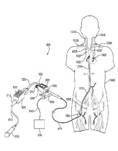
Turning now to one preferred illustrative use, Fig. 3 illustrates one
embodiment of the system in operation as well as one location and path for
positioning the distal end of a catheter of the type illustrated in Fig. 1,
Fig. 2a, or
Fig. 2b within the right atrium of the heart. Catheters other than those shown
in
Fig. 1, Fig.2a, and Fig.2b may be similarly positioned and used as well.
14
CA 02875516 2014-12-02
WO 2013/184782
PCT/US2013/044287
A first catheter 365 of a type similar to the one depicted in Fig. 1, Fig. 2a,
or Fig. 2b is initially prepared for the procedure by coupling a first
pressure
monitor 305 to a first pressure sensor 355 by a first sensor wire 350. Initial
setup
continues by coupling a second pressure monitor 330 to a second pressure
sensor
325 via a second sensor wire 320. Second pressure sensor 325 is coupled to a
pressure increasing device 315 configured to deliver the treatment agent. One
end
of inflation tube 370 is coupled to second port 360 of first catheter 365
while the
other end of inflation tube 370 is coupled to balloon inflation device 375
thus
completing setup. Examples of various embodiments of balloon inflation device
375 include syringes, metered pumps, and various types of balloon inflation
control devices used to monitor and control the pressure inside a catheter
balloon.
Examples of various embodiments of pressure increasing device 315 include a
syringe, a metered pump, or any of various other types of pumps or infusers
commonly used to push treatment agents through a catheter. Examples of various
treatment agents which might be used in the procedure include blood or blood
components, various pharmacological agents, infusion pellets, suspended cells,
stem cells, microspheres, peptide growth factors, and the like.
One example of a treatment procedure using first catheter 365 establishing
introducer sheath 385 in femoral vein 1005 in the thigh or groin area of
patient
1000. Although Fig. 3 indicates introducer sheath 385 is inserted in the
patient's
right thigh, insertion in the left thigh or groin area is also envisioned and
may be
preferable depending on the individual patient's situation. A guidewire (not
shown)
is extends through introducer sheath 385 into femoral vein 1005. The guidewire
preferably has a diameter between 0.014 and 0.018 inches and a flexible distal
tip
to make it easy to advance through the vasculature and into the vicinity of
the
selected target site, in this case the coronary sinus (not shown) attached to
right
atrium 1020 of the heart 1025. The guidewire is maneuvered into right atrium
1020
by guiding it into common iliac vein 1010, through inferior vena cava 1015,
and
into right atrium 1020 of heart 1025. The guidewire is then advanced into the
coronary sinus (shown in more detail in Fig. 7) and into the vicinity of one
or more
coronary veins (not shown).
CA 02875516 2014-12-02
WO 2013/184782
PCT/US2013/044287
The proximal end of the guidewire projecting from introducer sheath 385 is
positioned through the distal end of catheter shaft 380 finally exiting first
port 345
of first catheter 365. With the guidewire extending through first catheter
365,
catheter shaft 380 is maneuvered to the treatment site by gliding it over the
guidewire through introducer sheath 385 into femoral vein 1005, along the path
traversed by the guidewire up inferior vena cava 1015, into right atrium 1020
of
the heart 1025 and into the coronary sinus. Balloon inflation device 375 is
then
engaged to inflate the balloon which is positioned near the distal end of
first
catheter 365 in the coronary sinus and/or the adjacent cardiac vein thereby
holding
catheter shaft 380 in position while also occluding the coronary sinus and/or
cardiac vein. The guidewire is then withdrawn from first catheter 365 by
retracting
the guidewire proximally through first port 345. Throughout the withdrawal
process, hemostasis can be maintained by a hemostasis valve or other flow
restricting device (not shown) operatively coupled with first port 345 to keep
any
significant quantity of blood or other fluids from exiting first port 345
while the
guidewire is being withdrawn from catheter shaft 380.
After the guidewire is withdrawn, second catheter 340 is inserted into first
port 345 and advanced inside catheter shaft 380 through femoral vein 1005,
into
common iliac vein 1010, up inferior vena cava 1015, and into right atrium 1020
of
the heart 1025. Second catheter 340 moves through catheter shaft 380 exiting
its
distal tip to enter the treatment area where it is then steered to the precise
treatment
location (see Fig. 7). As with the guidewire positioning and withdrawal steps,
hemostasis may be maintained by a hemostasis valve or other similar flow
restricting device operatively coupled to first port 345 such that no more
than
insignificant quantities of blood or other fluids escape catheter shaft 380
through
first port 345 while the guidewire and second catheter 340 are being advanced
and
withdrawn. Throughout the procedure described here, standard medical
procedures
common to one of ordinary skill in the art can be followed to flush first
catheter
365, second catheter 340 and other necessary equipment with a saline solution
or
.. similar fluid as necessary to minimize the opportunity for air pockets to
be
introduced into the patient's vasculaturc. As well, a guidewire or other
guiding or
stiffening member may be inserted into a lumen of second catheter 340 during
16
CA 02875516 2014-12-02
WO 2013/184782
PCT/US2013/044287
advancement through first catheter 365. Such guidewire or other stiffening
member may then optionally be withdrawn prior to administration of a cellular
and/or other treatment agent as discussed below.
With second catheter 340 subselectively maneuvered into position within
the treatment area, delivery of the treatment agent may commence. As
illustrated in
Fig. 3, second catheter 340 functions as a treatment catheter or treatment
delivery
device. Second catheter 340 is coupled to second pressure sensor 325. A fluid
input device 315 then begins applying treatment agent under pressure into
second
catheter 340 thereby beginning the flow of treatment agent through a lumen of
second catheter 340 (e.g. a lumen from which a guidewire or other stiffening
member has been removed as discussed above) and into the treatment region. As
treatment progresses, second pressure sensor 325 relays pressure data through
second sensor wire 320 to second pressure monitor 330 which appears as second
pressure data 335. Likewise first pressure sensor 355 supplies pressure data
through first sensor wire 350 to first monitor 305 where it appears as first
pressure
data 310. Throughout the procedure, first pressure monitor 305 indicates the
fluid
pressure in the treatment region. Second pressure sensor 325, on the other
hand,
indicates fluid pressure of the treatment agent itself measured inside second
catheter 340 as the treatment agent is being delivered into the treatment
site. First
pressure sensor 335 gauges fluid pressure and stress on the walls of the
internal
passages (e.g. blood vessels) in the treatment area while second pressure
sensor
325 aids in gauging potential stress on the treatment agent itself (e.g.
cells) or
catheter structures caused by fluid pressure.
First pressure monitor 305 and second pressure monitor 330 appear in Fig.
3 as digital displays showing a historical graph of first pressure data 310
and
second pressure data 335. However, other embodiments are also envisioned such
as a mechanical gauge or other similar analog pressure indicator having no
electronic components. In another embodiment, first pressure monitor 305 and
second pressure monitor 330 only report the current pressure and have no
ability to
save past pressure data nor to indicate passed pressure data readings in a
graphical
form.
17
CA 02875516 2014-12-02
WO 2013/184782
PCT/US2013/044287
Another embodiment of a catheter useful for delivering a treatment agent
into a treatment region is shown at 400 in Fig. 4. The catheter at 400 has a
proximal end 405 and a distal end 475 and a catheter shaft 450 extending
between
the two ends. Proximal end 405 has a connector or hub 425 for coupling to
catheter
shaft 450 which extends the length of the catheter terminating at distal tip
480. The
proximal end of catheter shaft 450 is coupled to the distal end of connector
425 by
any appropriate means such as thermal bonding, adhesive bonding, bonding by
chemical reaction, or other non-detachable means as shown in Fig. 4. Other
embodiments may be desirable, such as an embodiment with a detachable coupling
using a threaded or snap fit coupler at the junction between connector 425 and
catheter shaft 450 allowing them to be detachable rather than permanently
coupled
together.
Connector 425 has an attachment collar 415 and ergonomic grips 420
which make it easier to attach the catheter to various other devices. A
flexible
sleeve 435 surrounds the junction between connector 425 and catheter shaft 450
giving the joint additional strength and durability while also making it
easier to
grip the catheter when attaching it to other devices. Connector 425 has a
central
lumen port 410 at the proximal tip which provides access to a central lumen
430
having an inside diameter 437. In one embodiment, inside diameter 437 is 0.022
inches; however, other inside diameters are also envisioned depending on the
treatment agent or other substance passing through central lumen 430 and the
size
constraints of the treatment area. In the embodiment illustrated at 400,
central
lumen 430 begins at proximal end 405 and continues along the central axis of
catheter shaft 450 through the catheter and terminating at distal tip 480.
In the embodiment shown at 400, catheter shaft 450 is constructed of
multiple concentric layers. Surrounding central lumen 430 is a liner 445 which
separates substances passing through central lumen 430 from reinforcing
material
447 and extends from the proximal end of catheter shaft 450 to distal tip 480.
Reinforcing material 447 can provide extra strength (e.g. column strength)
and/or
durability to catheter shaft 450. Reinforcing material 447 extends from the
proximal end of catheter shaft 450 to a termination region 470 some distance
from
distal tip 480. Surrounding reinforcing material 447 is flexible material 440
which
18
CA 02875516 2014-12-02
WO 2013/184782
PCT/US2013/044287
makes up the outer shell of catheter shaft 450. In one embodiment, reinforcing
material 447 is a layer of woven or braided metal or other reinforcing
material. In
another embodiment, reinforcing material 447 does not surround central lumen
430
but rather is present as one or more separate reinforcing or stiffening
members
running through catheter shaft 450 between liner 445 and flexible material
440. In
this embodiment, the separate reinforcing or stiffening member may be any sort
of
material providing increased rigidity such as one or more individual wires or
rods
made of plastic or metal. In another embodiment, flexible material 440 is
composed of various materials with stronger, more rigid materials used toward
the
proximal end to better resist physical deformation of catheter shaft 450 while
more
pliable and flexible materials are used in more distal sections of catheter
shaft 450
to make navigation through the vasculature less difficult.
At distal end 475, treatment catheter 400 has a set distal bend 465 which
deflects distal tip 480 away from the longitudinal axis of catheter shaft 450
to aid
in the navigation of treatment catheter 400 as it passes through the various
structures on its way to a treatment region. Distal end 470 also has a
plurality of
side ports 460 which allow the treatment agent moving through central lumen
430
to diffuse through the sides of distal end 475 in various directions rather
than
exiting through distal tip 480. The embodiment shown at 400 indicates multiple
ports 460. However no particular number or size of ports is intended by the
illustration in Fig. 4. Distal end 475 could have one port, two ports, or any
number
of ports appropriate to the successful release of the treatment agent. As
well, in
addition to or as an alternative to side port(s) 460, catheter 400 may have a
terminal distal port that directs fluids longitudinally out the very tip of
catheter
400. Furthermore, Fig. 4 indicates ports 460 penetrate catheter shaft 450 at
right
angles to the longitudinal axis of central lumen 430. However, the angle of
penetration indicated in Fig. 4 is illustrative only and various other angles
are
envisioned and may vary significantly depending on factors such as the
treatment
agent, the treatment region, the fluid pressure in central lumen 430 and the
like.
Also, the angle of distal bend 465 can be any suitable angle relative to the
longitudinal axis of catheter shaft 450, for example an angle in the range of
about 3
degrees to about 90 degrees. In some embodiments, the angle of bend 465 will
be
19
CA 02875516 2014-12-02
WO 2013/184782
PCT/US2013/044287
between 45 and 90 degrees relative to the longitudinal axis of catheter shaft
450,
while in others, an angle between 0 and 45 degrees may be preferable.
Considering the construction of the catheter shown in Fig. 4, various modes
are possible. For example, Fig. 4 shows catheter shaft 450 and connector 425
as
being constructed of multiple materials and coupled together. However, in
another
embodiment, connector 425 and catheter shaft 450 are constructed of the same
flexible material 440. In yet another embodiment, flexible material 440 is
manufactured from a biocompatible polymer embedded with radiopaque marking
indices appearing on the exterior surface of catheter shaft 450 as dots,
lines, rings
or other markings at various points, including distal tip 480 (see e.g. distal
tip
radiopaque marker 485). In yet another embodiment, catheter shaft 450 is
constructed using radiopaque filler, such as barium sulfate, thereby making
the
entire shaft radiopaque. By introducing radiopaque compounds and markings,
catheter shaft 450 is easier to observe under a fluoroscope simplifying the
process
of precise positioning within the body. In yet another embodiment, distal tip
480
can include a magnetically reactive coil to aid in visualization and
positioning
using magnetic resonance imaging. Such markings may also make catheter shaft
450 more visible when used with other forms of visualization discussed in some
detail below.
Fig. 4a shows another catheter 400a which has similar features to catheter
400 discussed above, which are similarly numbered. In addition, catheter 400a
includes an inflatable balloon 487 mounted on a distal region thereof, and an
inflation lumen 489 fluidly communicating with and useful for passage of a
fluid to
inflate balloon 487. Inflation lumen 489 fluidly communicates with port lumen
491 and ultimately inflation port opening 493 of hub or connector 425. In
certain
modes catheter 400a can be used as a subselective catheter in conjunction with
another catheter e.g. as described herein. Catheter 400a can be a
microcatheter, for
example having a catheter shaft with an outer diameter of about 0.018 inches
or
smaller. In one mode of use, balloon 487 can be inflated to occlude a vessel
that
has been subselectively catheterized (e.g. in conjunction with another, larger
balloon catheter as described herein), and a viable cellular preparation
and/or other
therapeutic agent can be delivered through the delivery lumen 430 and out of
ports
CA 02875516 2014-12-02
WO 2013/184782
PCT/US2013/044287
460. In other embodiments, in addition to or as an alternative to side ports
460,
catheter 400a can have a distal tip opening providing a port for longitudinal
delivery of the therapeutic preparation.
Fig. 4b shows another catheter 400b which has similar features to catheter
400 discussed above, which are similarly numbered. In addition, catheter 400b
includes an ultrasound emitting element 495 mounted on a distal region
thereof.
Element 495 is operable to emit ultrasound to the surrounding tissue region,
and
can for example be powered by a wire extending within a lumen wall of catheter
400b and/or within a dedicated lumen or shared lumen (e.g. lumen 430) of
catheter
400b. Suitable piezoelectric ultrasound emitting devices are known and can be
used herein. In certain modes of operation, ultrasound emitting element 495
can be
operated before, during and/or after the delivery of a viable cellular and/or
other
therapeutic substance from ports 460, in order to enhance the delivery of the
substance. In some modes of operation, the ultrasound emitted by element 495
can
be effective to increase the penetration of the cells and/or other therapeutic
substance through adjacent vessel (e.g. venous) walls. With reference now also
back to Fig. 4a, catheter 400a may also include an ultrasound emitting element
495. As with catheter 400a, in other embodiments, in addition to or as an
alternative to side ports 460, catheter 400b can have a distal tip opening
providing
a port for longitudinal delivery of the therapeutic preparation.
A multi-pressure monitoring system that may be used for cell therapy is
shown in Fig. 5, which is similar to the system shown in Fig. 3. The system
shown
in Fig. 5 has a first catheter 570 having an inflatable occlusion balloon (not
shown)
at its distal end for occluding areas within the treatment region as required
by the
specific treatment regimen. Catheter 570 has a catheter shaft 575 and a first
lumen
port 565 at the proximal end for accessing a first lumen (not shown) which
extends
through catheter shaft 575 and exits at or near the distal end. First catheter
570 also
has a balloon inflation port 560 which allows an inflation medium to pass
through
catheter shaft 575 inside a balloon inflation lumen (not shown) into the
inflation
void inside the occlusion balloon near the distal end of catheter shaft 575.
Coupled
to balloon inflation port 560 is a balloon inflation line 540 which carries
the
inflation medium from a balloon inflation device 535 through a balloon
inflation
21
CA 02875516 2014-12-02
WO 2013/184782
PCT/US2013/044287
port 560 into the balloon inflation lumen where it can be used to inflate the
balloon. First pressure sensing device 545 is coupled to first lumen port 565
to
measure the pressures inside the first lumen of catheter 570. First pressure
sensing
device 545 has an auxiliary inlet port 530 and a first treatment inlet port
550 and
displays first pressure data 555 indicating the current pressure inside the
treatment
area. First pressure data 555 may be indicated by any indicator operable to
communicate pressure to the user such as a liquid crystal display,
arrangements of
light emitting diodes, or by any of various analog indicators such as a needle
in a
gauge. A second catheter 525 enters first treatment inlet port 550, passes
through
first pressure sensing device 545, exits through first treatment outlet port
567, and
enters the first lumen of first catheter 570 through first lumen port 565.
Second
catheter 525 passes through the first lumen of catheter shaft 575 exiting at
or near
the distal end of first catheter 570 into the treatment area. Second catheter
525
maintains a sealing relationship with first treatment inlet port 550 so that
throughout the treatment procedure, no significant quantities of blood or
other
fluids can exit from first treatment inlet port 550 before, during and after
second
catheter 525 is inserted into first treatment inlet port 550. A second
pressure
sensing device 520 is coupled to second catheter 525 to measure the fluid
pressure
inside second catheter 525. Second pressure sensing device 520 displays second
pressure data 515 indicating the current pressure inside second catheter 525
as
treatment progresses. As with first pressure data 555, second pressure data
515
may be indicated by any sort of indicator such as a liquid crystal display, a
light
emitting diode display, or by any of various analog indicators such as a
needle in a
gauge. Treatment line 510 is coupled to a second treatment inlet port 512
allowing
the treatment agent passing from pressure increasing device 505 to move
through
treatment line 510, second treatment inlet port 512, second pressure sensing
device
520, second catheter 525, and into the treatment region. Suitable digital
pressure
monitors for use for first pressure sensing device 545 and second pressure
sensing
device 520 are commercially available from Mirador Biomedical (Seattle, WA)
under the brand name Compass.
In operation, one embodiment of the system shown in Fig. 5 can be
provided in initially disassembled condition such that catheter 570, balloon
22
CA 02875516 2014-12-02
WO 2013/184782
PCT/US2013/044287
inflation line 540, first pressure sensing device 545, second catheter 525,
second
pressure sensing device 520, treatment line 510, and pressure increasing
device
505 are not coupled together. However, in other embodiments, some or all of
these
components may already be coupled together using either nondestructively
detachable or nondetachable connectors or other means. One example of a
treatment procedure using first catheter 570 as part of the system shown in
Fig. 5
begins by establishing an introducer sheath 580 in femoral vein 1005 through
the
thigh or groin area of patient 1000, which can be achieved using standard
percutaneous access techniques. Although Fig. 5 illustrates introducer sheath
580
introduced into the right thigh or groin, insertion into the left thigh or
groin area is
also envisioned as well and may be preferable in some situations. A guidewire
extends through introducer sheath 580, which can be an initial guidewire used
for
percutaneous access or a newly introduced guidewire. The guidewire can in
certain
forms have a diameter between 0.014 and 0.018 inches and a flexible distal tip
that
allows it to bend easily as it is advanced through the body to the selected
site. The
guidewire is maneuvered into common iliac vein 1010, through inferior vena
cava
1015, and into right atrium 1020 of the heart 1025. The guidewire is then
advanced
into the coronary sinus (shown in more detail in Fig. 7) or other specific
treatment
area.
The distal end of first catheter 570 is advanced over the guidewire into
femoral vein 1005, into common iliac vein 1010, inferior vena cava 1015 and
into
right atrium 1020. A hemostasis valve may also be present in first lumen port
565
as necessary to avoid significant loss of blood or other fluids during the
catheter
insertion process. In some embodiments of first catheter 570, a hemostatic
device
is built into first lumen port 565 and therefore no additional hemostasis
valve over
flow restrictor is required to avoid loss of blood.
When first catheter 570 is correctly positioned, the guidewire can be
withdrawn from first lumen port 565 and first pressure sensing device 545 can
be
coupled to the proximal end of first catheter 570 by coupling a first lumen
port 565
to first treatment outlet port 567. Second catheter 525 can then be inserted
into
first treatment inlet port 550 and guided through first pressure sensing
device 545
and into the first lumen of first catheter 570 inside catheter shaft 575 until
reaching
23
CA 02875516 2014-12-02
WO 2013/184782
PCT/US2013/044287
the treatment region. Second catheter 525 is coupled to the treatment outlet
port on
second pressure sensing device 520 (not shown). Second treatment inlet port
512 is
coupled to treatment line 510 which is in turn coupled to fluid input device
505
which is operable to deliver the treatment agent. First pressure sensing
device 545
and second pressure sensing device 520 are activated and display first
pressure
data 555 and second pressure data 515 respectively.
With the pressure sensors, catheters, and treatment agent ready to be
administered, balloon inflation device 535 can be employed to inflate the
occlusion
balloon at the distal end of first catheter 570 to hold catheter shaft 575 in
place
while also occluding the necessary portions of and/or adjacent to the target
treatment region. Fluid input device 505 is operated to advance the treatment
agent
under pressure through a lumen of second catheter 525 to cause the treatment
agent
to flow into the treatment region. The increase in pressure within second
catheter
525 due to the forceful passage of the treatment agent will appear as second
pressure data 515 displayed by second pressure sensing device 520 and any
corresponding changes in pressure within the in the treatment region will
appear as
first pressure data 555 displayed by first pressure sensing device 545. The
operator
can then monitor pressure data 515, 555 and adjust the pressure generated by
fluid
input device 505 accordingly, or make other necessary changes to optimize the
therapy and/or avoid adverse effects to patient 1000 or to the treatment agent
being
administered.
While pressure monitoring in the target treatment region and in the
treatment agent delivery lumen are identified and provided for in the
preferred
embodiments herein, it will be understood that pressure monitoring in other
vascular locations during delivery of the therapeutic agent may also be
undertaken.
These include, for example, pressure measurement within congruent vessel
structures, for example arterial-side pressure monitoring when applying venous-
side retroperfusion or other delivery, or venous-side pressure monitoring in
regions
other than the target delivery region, e.g. for comparative purposes. These
and
other variations will be apparent to the person skilled in the field from the
descriptions herein.
24
CA 02875516 2014-12-02
WO 2013/184782
PCT/US2013/044287
Fig. 3 and Fig. 5 illustrate the insertion of catheters in the groin or thigh
area. Fig. 6 illustrates at 600 an alternate insertion point which may be
preferable
for some patients. An introducer sheath 610 is established percutaneously in
the
right internal jugular vein 1040 in the right side of the neck of patient
1000, instead
of into a femoral vein as shown in Fig. 3 and Fig. 5. The procedure is
continues as
described above wherein a guidewire is extended through internal jugular vein
1040 and is maneuvered downward through the right innominate vein 1023, into
superior vena cava 1027, and into right atrium 1020 of heart 1025 from above.
Catheter shaft 605, which is similar to catheter shaft 380 shown in Fig. 3 and
catheter shaft 575 shown in Fig. 5, is guided over the guidewire into right
atrium
1020 of heart 1025. Equipment similar to that shown in Fig. 3 or Fig. 5
described
above is then engaged as previously described to perform the treatment using
the
alternate insertion point. Other alternate insertion points are also
envisioned. For
example, introducer sheath 610 can also be established in left internal
jugular vein
1045 in which case catheter shaft 605 is maneuvered through left internal
jugular
vein 1045 into left innominate vein 1035, into superior vena cava 1027 and
right
atrium 1020 of the heart 1025. Also, introducer sheath 610 may be established
in
left subclavian vein 1035 allowing catheter shaft 605 to pass through left
subclavian vein 1035 and left innominate vein 1037 and into superior vena cava
.. 1027 and into right atrium 1020. A similar positioning may be used but from
the
opposite side by inserting introducer sheath 610 into right subclavian vein
1030 in
which case catheter shaft 605 can be maneuvered through right subclavian vein
1030 into right innominate vein 1023 and into the superior vena cava 1027 and
right atrium 1020.
Fig. 7 illustrates at 700 one positioning of the distal end of a catheter
system used for cell or other therapy of a type similar to the catheters
illustrated in
Fig. 1-5 and described above. In Fig. 7, catheter 720 is positioned within the
coronary sinus 1120 of the heart according to the techniques described above,
or
by other suitable technique. Fig. 7 shows a posterior view of the heart and
illustrates several of the major blood vessels. The blood vessels, veins,
arteries, and
other major structures depicted in Fig. 7 are illustrative and are not
necessarily
anatomically correct in every detail regarding position, size, and relative
scale.
CA 02875516 2014-12-02
WO 2013/184782
PCT/US2013/044287
Several coronary veins 1105, 1110, and 1115, arc illustrated and shown
covering
left ventricle 1100 and right ventricle 1135. These coronary veins branch off
from
coronary sinus 1120, a cutaway view of which is shown in Fig.7. Above coronary
sinus 1120 in Fig. 7 is left atrium 1125, and aorta 1130. Right atrium 1145
serves
as the entry point for superior vena cava 1140, inferior vena cava 1160, and
coronary sinus 1120. Superior vena cava 1140 delivers oxygen depleted blood
from the upper half of the body while inferior vena cava 1160 delivers oxygen
depleted blood from the lower half of the body. Coronary sinus 1120, provides
a
similar function with regard to the heart itself delivering oxygen depleted
blood
from the myocardial tissue to the right atrium through coronary sinus ostium
1150.
First catheter 720 is positioned generally in coronary sinus 1120 as
illustrated in Fig. 7. Catheter shaft 725 enters right atrium 1145 through
opening
1155 and turns to enter coronary sinus 1120 through coronary sinus ostium
1150.
Catheter balloon 715 is adapted to occlude the coronary sinus or another
vessel
when inflated. In Fig. 7, catheter balloon 715 is positioned within coronary
sinus
1120 and is inflated to partially or completely block the normal flow of
oxygen
depleted blood from the coronary sinus through coronary sinus ostium 1150and
into the right atrium. A second catheter 705 operating as a treatment delivery
catheter is shown exiting distal tip 710 of first catheter 720 and entering
coronary
vein 1105. Second catheter 705 is positioned in this manner to deliver an
appropriate treatment agent which may include fluids such as blood or blood
components, various drugs, infusion pellets, suspended cells, stem cells,
microspheres, peptide growth factors, DNA, RNA or other treatment agents, or
any
combination thereof. The treatment agent exiting second catheter 705 can be
delivered into the myocardial tissue e.g. via the capillary beds in the
treatment area
opposite the normal circulation of blood from the coronary sinus 1120 into
right
atrium 1020 which is at least partially stopped by catheter balloon 715. When
present, a set curve in a distal portion of second catheter 705, e.g. as
discussed in
conjunction with catheters above, can facilitate steering the catheter 705
subselectively into various branches or regions of the local vasculaturc for
delivery
of the treatment agent.
26
CA 02875516 2014-12-02
WO 2013/184782
PCT/US2013/044287
Fig. 7 shows one possible positioning of second catheter 705, catheter
balloon 715, and first catheter 720 for the introduction of an appropriate
treatment
agent. Depending on the desired outcome, the treatment agent used, and the
procedure followed, catheter balloon 715 and first catheter 720 may be
positioned
deeper within coronary sinus 1120 or closer to coronary sinus ostium 1150,
and/or
within a coronary vein (e.g. an anterior descending coronary vein), thereby
facilitating the positioning of second catheter 705 into other coronary veins
such as
1110, 1115, or other veins not shown in Fig.7. Likewise, the extent to which
second catheter 705 extends beyond distal tip 710 of first catheter 720 is
determined by the desired treatment as well. For example, it may be desirable
to
extend second catheter 705 further into coronary vein 1105, or into other
coronary
veins or vessels not shown in Fig. 7 to affect treatment in areas further
removed
from distal tip 710 and first catheter 720. One embodiment of second catheter
705
is similar to the catheter illustrated in Fig. 4 and described above which has
a tip
that has a set curve or bend from the longitudinal axis of second catheter 705
to aid
in the process of traversing the tight corners and narrow passageways of the
coronary veins branching out from coronary vein 1105, as discussed above.
Using the catheter illustrated in Fig. 7, other treatment options are also
possible. For example, in a similar procedure, second catheter 705 is inserted
deeper into a coronary vein such as coronary vein 1105, 1110, or 1115 and
catheter
balloon 715 is inflated to occlude coronary sinus 1120. As a treatment agent
is
infused from second catheter 705, second catheter 705 is simultaneously
withdrawn gradually from coronary vein 1105 as the treatment agent is released
into the myocardial tissue. As second catheter 705 passes the various branches
of
coronary vein 1105 during removal, second catheter 705 is advanced into these
lesser branches of coronary vein 1105. The process is repeated whereby second
catheter 705 is advanced into the lesser branch, and the treatment agent is
delivered
into these lesser branches of coronary vein 1105 as catheter 705 is then
gradually
withdrawn. This process allows for a more complete regional infiltration of
the
treatment agent into the myocardium in the treatment area.
Various techniques for guiding and positioning the catheter, guidewire, and
catheter balloon illustrated in Fig. 1 through Fig. 7 are available depending
on the
27
CA 02875516 2014-12-02
WO 2013/184782
PCT/US2013/044287
goals of the treatment and the location of the treatment region. A common
technique for aiding in catheter and guidewire positioning is to inject
radiocontrast
dyes into the bloodstream causing the blood vessels to be more easily visible
under
a fluoroscope. Another technique mentioned in the embodiments above that may
be used in concert with radiocontrast dyes is to use a catheter having
radiopaque
markings or a catheter that is constructed with radiopaque filler material in
the
catheter shaft. These markings make the catheter or selected portions thereof
visible under a fluoroscope as well. Once the blood vessels and catheter are
both
visible with the aid of fluoroscopy, the operator can use fluoroscopy to see,
and
manually control, the movements of the catheter in real-time as it is advanced
through the patient's body and into the treatment region.
Recent techniques have been developed involving computers and advanced
imaging techniques that significantly enhance the operator's ability to
precisely
navigate a catheter or guidewire into a treatment region. Any or all such
techniques
may be employed in treatment methods and systems described herein. In one
example, an imaging technique such as computed tomography angiography,
ultrasound or magnetic resonance imaging can be used to create a two-
dimensional
or three-dimensional map of the vasculature of a target region of a patient's
heart.
Such a map can be used in planning one or more target regions for receipt of
the
treatment agent. A catheter is then inserted percutaneously and guided into
the
treatment area through a coronary vein or artery, while imaging the movement
of
the catheter in real time, for example using at least a distal tip
fluoroscopic marker
(e.g. radiopaque markers 485 in the Figs. herein) or other suitable imaging
marker.
This real time image is overlaid upon the map as the procedure is conducted to
facilitate effective application of the therapy by a user referencing the real-
time
image and map. Such an arrangement may improve accuracy, reduce the chance of
misdirection into the wrong vessel or damage to the vessels themselves, and
allows
for precision positioning of the catheter and administration of the treatment
agent.
As to the treatment or therapeutic agent administered, in certain
embodiments, any one or combination of a wide variety of cellular preparations
may administered to a patient using a device, system or method described
herein.
For example, the cells can be skin cells, skeletal muscle cells, cardiac
muscle cells,
28
lung cells, mesentery cells, or adipose cells. The adipose cells may be from
omental
fat, properitoneal fat, perirenal fat, pericardial fat, subcutaneous fat,
breast fat, or
epididymal fat. In certain embodiments, the cells comprise stromal cells, stem
cells,
or combinations thereof. As used herein, the term "stem cells" is used in a
broad sense
and includes traditional stem cells, adipose derived stem cells, progenitor
cells,
preprogenitor cells, reserve cells, and the like. Exemplary stem cells include
embryonic stem cells, adult stem cells, pluripotent stem cells, neural stem
cells, liver
stem cells, muscle stem cells, muscle precursor stem cells, endothelial
progenitor cells,
bone marrow stem cells, chondrogenic stem cells, lymphoid stem cells,
mesenchymal
stem cells, hematopoietic stem cells, central nervous system stem cells,
peripheral
nervous system stem cells, and the like. Additional illustrative cells which
can be
used include hepatocytes, epithelial cells, Kupffer cells, fibroblasts,
neurons,
cardiomyocytes, myocytes, chondrocytes, pancreatic acinar cells, islets of
Langerhans,
osteocytes, myoblasts, satellite cells, endothelial cells, adipocytes,
preadipocytes,
biliary epithelial cells, and progentior cells of any of these cell types.
In some embodiments, the cells are, or include, endothelial progenitor cells
(EPCs). Preferred EPCs for use in the invention are endothelial colony forming
cells
(ECFCs), especially ECFCs with high proliferative potential. Suitable such
cells are
described for example in U.S. Patent Application Publication No. 20050266556,
and
U.S. Patent Application Publication No. 20080025956. Such ECFC cells can be a
clonal population, and/or can be obtained from umbilical cord blood of humans
or
other animals. Additionally or alternatively, the endothelial colony forming
cells have
the following characteristics: (a) express the cell surface antigens CD31,
CD105,
CD146, and CD144; and/or (b) do not express CD45 and CD14; and/or (c) ingest
acetylated LDL; and/or (d) replate into at least secondary colonies of at
least 2000
cells when plated from a single cell; and/or (e) express high levels of
telomerase, at
least 34% of that expressed by HeLa cells; and/or (f) exhibit a nuclear to
cytoplasmic
ratio that is greater than 0.8; and/or (g) have cell diameters of less than
about 22
microns. Any combination of some or all of these features (a)-(g) may
characterize
ECFCs used in the present invention.
29
CA 2875516 2019-10-02
In other embodiments, the cells are, or include, muscle derived cells,
including
muscle derived myoblasts and/or muscle derived stem cells. Suitable such stem
cells
and methods for obtaining them are described, for example, in U.S. Patent No.
6,866,842 and U.S. Patent No. 7,155,417. The muscle derived cells can express
desmin, M-cadherin, MyoD, myogenin, CD34, and/or Bc1-2, and can lack
expression
of CD45 or c-Kit cell markers.
In still other embodiments, the cells are, or include, stem cells derived from
adipose tissue. Suitable such cells and methods for obtaining them are
described for
example in U.S. Patent No. 6,777,231 and U.S. Patent No. 7,595,043. The
cellular
population can include adipose-derived stem and regenerative cells, sometimes
also
referred to as stromal vascular fraction cells, which can be a mixed
population
including stern cells, endothelial progenitor cells, leukocytes, endothelial
cells, and
vascular smooth muscle cells, which can be adult-derived. In certain forms,
the
cellular preparation can include adipose-derived cells that can differentiate
into two or
more of a bone cell, a cartilage cell, a nerve cell, or a muscle cell.
The uses of the terms "a" and "an" and "the" and similar references in the
context of describing the invention (especially in the context of the
following claims)
are to be construed to cover both the singular and the plural, unless
otherwise
indicated herein or clearly contradicted by context. Recitation of ranges of
values
herein are merely intended to serve as a shorthand method of referring
individually to
each separate value falling within the range, unless otherwise indicated
herein, and
each separate value is incorporated into the specification as if it were
individually
recited herein. All methods described herein can be performed in any suitable
order
unless otherwise indicated herein or otherwise clearly contradicted by
context. The
use of any and all examples, or exemplary language (e.g., "such as") provided
herein,
is intended merely to better illuminate the invention and does not pose a
limitation on
the scope of the invention unless otherwise claimed. No language in the
specification
should be construed as indicating any non-claimed element as essential to the
practice
of the invention.
CA 2875516 2019-10-02
While the invention has been illustrated and described in detail in the
drawings
and foregoing description, the same is to be considered as illustrative and
not
restrictive in character, it being understood that only the preferred
embodiment has
been shown and described and that all changes and modifications that come
within the
spirit of the invention are desired to be protected.
31
CA 2875516 2019-10-02