Note: Descriptions are shown in the official language in which they were submitted.
CA 02876399 2014-12-11
WO 2013/191907 PCT/US2013/044248
A WIRELESS TELEMETRY SYSTEM
INCLUDING AN INDUCTION POWER SYSTEM
FIELD OF THE INVENTION
The present invention relates generally to monitoring operating environments
and, in particular, to instrumented components and telemetry systems enabled
for
wirelessly transmitting electronic data indicative of individual component
condition
within an operating environment such as that of a combustion turbine engine.
BACKGROUND OF THE INVENTION
Embodiments of the present invention provide high temperature wireless
telemetry systems configured for operation on rotating or stationary
components
within an operating environment having an operating temperature up to
approximately 450 C or greater, such as within certain sections of a
combustion
turbine engine.
An exemplary high temperature telemetry system for use in a combustion
turbine engine may include at least one sensor deposited on a component such
as a
turbine blade. A telemetry transmitter circuit may be affixed to the turbine
blade and
a connecting material may be attached or deposited on the turbine blade for
routing
electronic data signals from the sensor to the telemetry transmitter circuit,
the
electronic data signals indicative of a condition of the turbine blade. An
induction
power system is provided for powering the telemetry transmitter circuit with a
rotating
data antenna affixed to the component, such as the turbine blade; and a
stationary
data antenna affixed to a static seal segment adjacent to the turbine blade.
In an embodiment of the telemetry system a resonant energy system is used
in conjunction with the rotating data antenna and the stationary data antenna.
More
specifically, a primary coil (which may be in the form of a probe or antenna),
or
power/energy transmitting device, is positioned at a stationary location in
the turbine
or compressor proximate to a secondary coil or power/energy receiving device
that is
affixed to the rotating components. The primary coil or antenna transmits an
oscillating current signal and the secondary coil is in resonance at generally
the
same frequency as a transmitting frequency of the oscillating current signal.
The
secondary coil and the rotating data antenna are fabricated on a same
substrate on
which the telemetry transmitter circuit is fabricated. Alternatively, one or
both of the
1
CA 02876399 2014-12-11
WO 2013/191907 PCT/US2013/044248
secondary coil and/or the rotating data antenna may be disposed on an airfoil
portion
of a turbine or compressor blade. In an embodiment, the primary coil may be
mounted to a casing or stationary component for the compressor or turbine
proximate to and in spaced relation to a tip of the blade.
Sensors in connection with a rotating component such as a compressor or
turbine blade are electrically linked to the telemetry transmitter circuit
which
processes and routes electronic data signals indicative of a condition of the
rotating
component to the rotating data antenna. The rotating data antenna then
transmits
the electronic data signals to the stationary antenna which then transmits
signals to a
receiver and/or processor.
In another embodiment, a stationary telemetry transmitter circuit is disposed
within the compressor and turbine, and used in conjunction with the above-
referenced rotating telemetry transmitter circuit mounted to a blade. One or
more
sensors in connection with stationary components transmit electronic data
signals
indicative of the stationary component to the stationary transmitter circuit,
which in
turn processes and routes the electronic data signals to the stationary data
antenna.
Accordingly; the stationary data antenna is configured to transmit electronic
data
signals indicative of operating conditions of the stationary and rotating
components
to a receiver for processing.
BRIEF DESCRIPTION OF THE DRAWINGS
FIG. 1 is a cross sectional view of an exemplary combustion turbine.
FIG. 2 is a perspective view of an exemplary combustion turbine vane.
FIG. 3 is a side view of the vane of FIG. 2.
FIG. 4 is an exemplary heat flux sensor deposited on a substrate.
FIG. 5 is a perspective view of an exemplary turbine blade, sensor and
wireless telemetry device.
FIG. 6 is a schematic of an exemplary wireless telemetry device.
FIG. 7 is a partial perspective view of an exemplary compressor blade..
FIG. 8 is a partial side view of the exemplary compressor blade of FIG. 7.
FIG. 9 is a partial cross sectional view of the exemplary turbine blade of
FIG. 5.
2
CA 02876399 2014-12-11
WO 2013/191907 PCT/US2013/044248
FIG. 10 is a perspective view of the exemplary turbine blade of FIG. 9, an
exploded view of a telemetry transmitter housing and an exemplary rotating
antenna
assembly mounted to the turbine blade.
FIG. 11 is an exploded view of an exemplary embodiment of the telemetry
transmitter housing of FIG. 10.
FIG. 12 illustrates components of an exemplary rotating antenna assembly.
FIG. 13 is a partial perspective view on a turbine static seal having an
exemplary embodiment of a stationary antenna assembly mounted thereto.
FIG. 14 is a partial cross sectional view of the turbine static seal of FIG.
12
and a turbine blade assembly having an exemplary rotating power and antenna
assembly mounted thereto.
FIG. 15 is a block diagram of an exemplary telemetry transmitter circuit.
FIG. 16 is a schematic of an exemplary induction power driver circuit.
FIG. 17 is a partial perspective view of a blisk having thereon wireless
telemetry components including a sensor and a telemetry device.
FIG. 18 is a schematic illustration of a telemetry device linked to a sensor.
FIG. 19 is a schematic illustration of circuits for a resonant energy transfer
system.
FIG. 20 is a schematic representation of a rotating data antenna.
FIG. 21 is a sectional schematic illustration of a telemetry device on a rotor
of
a blisk including a rotating data antenna on the blisk and a stationary
antenna on a
stator.
FIG. 22 illustrates a transmitter device housed within an RF transparent
cover.
FIG. 23 is an embodiment of the wireless telemetry system wherein an energy
receiving coil is on a blade for a blisk.
FIG. 24 is an embodiment of the wireless telemetry system wherein an energy
receiving coil and the rotating data antenna are on a blade for a blisk.
FIG. 25 is an embodiment of the wireless telemetry system wherein a
stationary telemetry circuit and stationary antenna are used to transmit data
relating
to stationary components and rotating components.
FIG. 26 is a perspective view of primary induction assemblies mounted to a
static seal segment of a stator.
3
CA 02876399 2014-12-11
WO 2013/191907 PCT/US2013/044248
FIG. 27 is a perspective view of a schematic representation of a planar
winding and magnetic core on a ceramic substrate.
FIG. 28 is a perspective view of a schematic representation of a planar
winding without a magnetic core on a ceramic substrate.
FIG. 29 is a schematic cross-sectional view of circuit board with a plurality
of
ceramic dielectric layers and planar windings formed thereon.
FIG. 30A is an elevational view of the top or first conductive layer of the
circuit
board of FIG. 29.
FIG. 303 is an elevational view of a second conductive layer of the circuit
board of FIG. 29.
FIG. 30C is an elevational view of a third conductive layer of the circuit
board
of FIG. 29.
FIG. 30D is an elevational view of a bottom or fourth conductive layer of the
circuit board of FIG. 29.
FIG. 31 is an embodiment of the wireless telemetry system incorporating
primary and secondary induction power assemblies that include planar windings
formed on ceramic boards.
DETAILED DESCRIPTION OF THE INVENTION
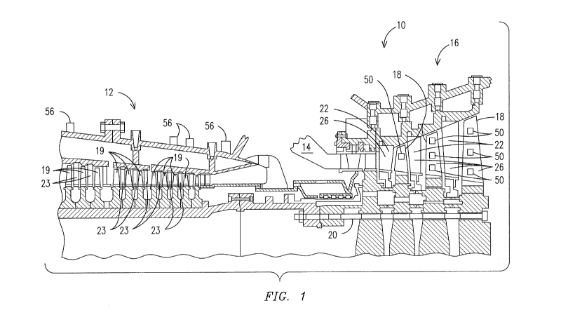
FIG. 1 illustrates an exemplary combustion turbine 10 such as a gas turbine
used for generating electricity. Embodiments of the invention may be used with
combustion turbine 10 or in numerous other operating environments and for
various
purposes. Combustion turbine 10 includes a compressor 12, at least one
combustor
14 (broken away) and a turbine 16. Compressor 12, combustor 14 and turbine 16
are sometimes referred to collectively as a gas or combustion turbine engine
10.
Turbine 16 includes a plurality of rotating blades 18, secured to a rotatable
central
shaft 20. A plurality of stationary vanes 22 are positioned between blades 18,
with
vanes 22 being dimensioned and configured to guide air over blades 18. Blades
18
and vanes 22 will typically be made from nickel-based alloys, and may be
coated
with a thermal barrier coating ("TBC") 26, such as yttria-stabilized zirconia.
Similarly,
compressor 12 includes a plurality of rotating blades 19 positioned between
respective vanes 23.
4
CA 02876399 2014-12-11
WO 2013/191907 PCT/US2013/044248
In use, air is drawn in through compressor 12, where it is compressed and
driven towards combustor 14. Combustor 14 mixes the air with fuel and ignites
it
thereby forming a working gas. This working gas temperature will typically be
above
about 130000. This gas expands through turbine 16, being guided across blades
18
by vanes 22. As the gas passes through turbine 16, it rotates blades 18 and
shaft
20, thereby transmitting usable mechanical work through shaft 20. Combustion
turbine 10 may also include a cooling system (not shown), dimensioned and
configured to supply a coolant, for example, steam or compressed air, to
blades 18
and vanes 22.
The environment within which turbine blades 18 and vanes 22 operate is
particularly harsh, subject to high operating temperatures and a corrosive
atmosphere, which may result in serious deterioration of blades 18 and vanes
22.
This is especially likely if TBC 26 should spall or otherwise deteriorate.
Embodiments of the invention are advantageous because components may transmit
real time or near real time data indicative of a component's condition during
operation of combustion turbine 10.
U.S. Patent No. 6,576,861, the disclosure of which is specifically
incorporated
herein by reference, discloses a method and apparatus that may be used to
deposit
embodiments of sensors and connectors for connecting sensors with transmitters
or
otherwise routing data signals. In this respect, methods and apparatus
disclosed
therein may be used for the patterning of fine sensor and/or connector
features of
between about 100 microns and 500 microns without the need of using masks.
Multilayer electrical circuits and sensors may be formed by depositing
features using
conductive materials, resistive materials, dielectric materials, insulative
materials and
other application specific materials. Alternate methods may be used to deposit
multilayer electrical circuits, sensors and connectors such as thermal
spraying, vapor
deposition, laser sintering and curing deposits of material sprayed at lower
temperatures may be used as well as other suitable techniques.
FIG. 2 illustrates a pair of adjacent vanes 23 removed from compressor 12
with one vane 23 having a sensor 50 mounted or connected thereto for detecting
a
condition of the vane. A lead line or connector 52 may be deposited as a means
for
routing a data signal from sensor 50 to a transmitter 54 configured for
wirele.ssly
transmitting the data signal to a transceiver 56. Connector 52 may be one or a
CA 02876399 2014-12-11
WO 2013/191907 PCT/US2013/044248
plurality of electrical leads for conducting a signal from sensor 50 to
transmitter 54.
Alternate embodiments allo\,v for various types of connectors 52 to be used as
a
means for routing a data signal from sensor 50 to transmitter 54, depending on
the
specific application.
Transmitters 54 may be multi-channel and have various specifications
depending on their location within a casing of combustion turbine 10.
Transmitters
54 may be configured to function within the early stages of compressor 12,
which are
subject to operating temperatures of between about 80 C to 120 C. Transmitters
54
may be configured to function within later stages of compressor 12 and/or
stages of
turbine 16 subject to operating temperatures of greater than about 120 C and
up to
about 300 C. Transmitters 54 may be fabricated using silicon-on-insulator
(S01)
technology and other materials capable of operating in regions with
temperatures
greater than about 120 C.
FIG. 3 illustrates a schematic plan view of compressor vane 23 having sensor
50 connected therewith and connector 52 connecting sensor 50 with transmitter
54.
A power source 51 may be provided, such as an appropriately sized battery for
powering transmitter 54. Transmitter 54 may receive signals from sensor 50 via
connector 52 that are subsequently wirelessly transmitted to transceiver 56.
Transceiver 56 may be mounted on hub 58 or on a surface external to compressor
12 such as the exemplary locations shown in FIG. 1. Transceiver 56 may be
mounted in various locations provided it is within sufficient proximity to
transmitter 54
to receive a wireless data transmission, such as an RF signal from transmitter
54.
One or more sensors 50 may be connected with one or more compressor
vanes 23 by fabricating or depositing sensors 50 and connectors 52 directly
onto a
surface of vane 23. Connector 52 may extend from sensor 50 to a termination
location, such as the peripheral edge of vane 23 so that a distal end 53 of
connector
52 is exposed for connection to transmitter 54. Sensor 50 and connector 52 may
be
positioned on vane 23 to minimize any adverse affect on the aerodynamics of
vane
23. Embodiments allow for a distal end 53 of connectors 52 to be exposed at a
termination location, which may be proximate a peripheral edge of a component
or
other suitable location. This allows a field technician to quickly and easily
connect
connector 52 to a transmitter 54 regardless of its location.
6
CA 02876399 2014-12-11
WO 2013/191907 PCT/US2013/044248
FIG. 4 illustrates an exemplary sensor 61 that may be deposited within a
barrier coating such as TBC 60, which may be yttria-stabilized zirconia. TBC
60 may
be deposited on a bond coat 62, which may be deposited on a substrate 64.
Substrate 64 may be various components such as a superalloy suitable for use
in
turbine 16 such as a turbine blade 18. Sensor 61 may be formed for various
purposes and may include thermocouples 66 deposited using conventional K, N,
5,
B and R-type thermocouple material, or any combination of their respective
constituent elements provided that the combination generates an acceptable
thermoelectric voltage for a particular application within combustion turbine
10.
Type K thermocouple materials NiCr or NiAl may be used in sections of
compressor 12 having an operating environment up to approximately 800 C. For
example, NiCr(20) may be used to deposit a strain gage in compressor 12, Type
N
thermocouple material, such as alloys of NiCrSi and NiSi, for example, may be
used
for depositing sensors in sections of turbine 16 having an operating
environment
between approximately 800 C to 1150 C.
Type 5, B and R thermocouple materials may be used for depositing sensors
in sections of turbine 16 having an operating environment between
approximately
1150 C to 1350 C. For example, Pt-Rh, Pt-Rh(10) and Pt-Rh(13) may be deposited
to form sensors 50 within turbine 16 provided that the material generates an
acceptable thermoelectric voltage for a particular application within
combustion
turbine 10. Ni alloys, for example, NiCr, NiCrSi, NiSi and other oxidation-
resistant
Ni-based alloys such as MCrAIX, where M may be Fe, Ni or Co, and X may be Y,
Ta,
Si, Hf, Ti, and combinations thereof, may be used as sensing materials for
high
temperature applications in deeper sections of compressor 12 and throughout
turbine 16. These alloys may be used as sensing material deposited in various
sensing configurations to form sensors such as heat flux sensors, strain
sensors and
wear sensors.
Components within combustion turbine 10, such as blades 18, 19 and/or
vanes 22, 23 may have application specific sensors 50 deposited to conform to
a
component's surface and/or embedded within a barrier or other coating
deposited
within combustion turbine 10. For example, FIG, 5 shows an exemplary turbine
blade 70, which may be a blade from row 1 of turbine 16, having high
temperature
resistant lead wires, such as connectors 72 deposited to connect an embedded
or
7
CA 02876399 2014-12-11
WO 2013/191907 PCT/US2013/044248
surface mounted sensor 74 with a wireless telemetry device 76. Device 76 may
be
mounted in a location where the telemetry components are exposed to relatively
lower temperatures, such as proximate the root 78 of blade 70 where the
operating
temperature is typically about 150 C - 250 C and higher.
Silicon-based electronic semiconductors, such as those that may be used for
transmitting data, may have limited applications due to their operational
temperature
constraints. Temperature and performance properties of silicon and silicon-on-
insulator (SOI) electronic chip technologies may limit their applications to
operating
environments of less than about 200 C. Aspects of the invention allow for such
electronic systems to be deployed for wireless telemetry device 76 within
compressor 12, which typically has an operating temperature of about 100 C
150 C.
Embodiments of wireless telemetry sensor systems may be configured to
operate within higher temperature regions present in later stages of
compressor 12,
and within turbine 16. These regions may have operating temperatures of about
150
C-250"C and higher. Materials having temperature and electrical properties
capable of operation in these higher temperature regions may be used for
depositing
sensors 50, 74, connectors 52, 72 and fabricating wireless telemetry devices
76.
Sensors 50, 74 and high temperature interconnect lines or connectors 52, 72
may be deposited using known deposition processes such as plasma spraying, EB
PVD, CVD, pulsed laser deposition, mini-plasma, direct-write, mini-HVOF or
solution
plasma spraying. Typically, dynamic pressure measurements, dynamic and static
strain, and dynamic acceleration measurements are desired on both stationary
and
rotating components of combustion turbine 10 together with component surface
temperature and heat flux measurements. Thus, embedded or surface mounted
sensors 50, 74 may be configured as strain gages, thermocouples, heat-flux
sensors, pressure transducers, micro-accelerometers as well as other desired
sensors.
FIG. 6 is a schematic of a representative embodiment of a wireless telemetry
device 76. Device 76 may be formed as a circuit board or integrated chip that
includes a plurality of electronic components such as resistors, capacitors,
inductors,
transistors, transducers, modulators, oscillators, transmitters, amplifiers,
and diodes
either embossed, surface mounted or otherwise deposited thereon with or
without an
8
CA 02876399 2014-12-11
WO 2013/191907 PCT/US2013/044248
integral antenna and/or power source. Embodiments of wireless telemetry device
76
may be fabricated for use in compressor 12 and/or turbine 16.
Wireless telemetry device 76 may include a board 80, an electronic circuit 90,
an operational amplifier 92, a modulator 94 and an RF oscillator/transmitter
96
electrically connected with each other via interconnects 98. The embodiment of
FIG.
6 is an exemplary embodiment and other embodiments of device 76 are
contemplated depending on performance specifications and operating
environments.
Embodiments of device 76 allow for a power source 100, and a transmitting and
receiving antenna 102 to be fabricated on board 80 thereby forming a
transmitter
such as transmitter 54 shown in FIGS. 2 and 3, or wireless telemetry device
76,
shown in FIG. 5.
PG. 7 illustrates a partial perspective view of an exemplary blade, such as a
blade 110 having a blade root 112, which may be a compressor blade within
compressor 12. One or more recesses or trenches 114 may be formed within root
112 such as within the bottom of blade root 112. Recesses 114 may be formed in
various shapes or dimensions and located within blade root 112 at various
places
along its length. One or more recesses or trenches 116 may be formed in one or
more faces 118 of blade root 112. Recesses 116 may be formed in various shapes
or dimensions and located within blade root 112 at various places within a
face 118.
Recesses 114, 116 may be formed using various methods such as by milling them
out after blade 110 is cast or by forming them as part of the blade 110 mold.
FIG. 8 illustrates compressor blade 110 instrumented with components of
wireless telemetry device 76 affixed within blade root 112. In this respect,
alternate
embodiments of wireless telemetry device 76 allow for one or more electrical
components 90, 92, 94, 96, 100, 102, shown in FIG. 6, to be mounted separately
or
contained on discrete boards 80 that are electrically connected and affixed
with an
instrumented component such as blade root 112. For example, a transmitting and
receiving antenna 102 shown in FIG. 6 may be mounted separately from and
electrically connected with board 80 having a transmitter 122 formed thereon
and
being electrically connected with antenna 102.
Antenna 120 may be seated within recess 116 and transmitter 122 may be
seated within recess 114. In this aspect, antenna 120 and transmitter 122 are
not
mounted/embossed or deposited onto a board 80. In other embodiments, antenna
9
CA 02876399 2014-12-11
WO 2013/191907 PCT/US2013/044248
120 may be deposited on a wireless telemetry board 80, as shown in FIG. 6, and
the
data may be transmitted using wireless telemetry to a receiver such as a
stationary
mounted transceiver 56. Power source 100 may be integral with board 80 or
located
separately from the board and mounted as a discrete component.
FIG. 9 illustrates a partial view of an exemplary blade 130, which may be a
turbine blade such as one of the turbine blades 18. Turbine blade 130 includes
a
root portion 132 defining an outer mold line for mating with a rotor disk of
turbine 16
within which blade 130 may be secured for operation of combustion turbine 10.
Sensing material may be deposited on blade 130 or within a barrier coating
deposited on the blade's surface to form a sensor 134. Connecting material may
be
deposited to form connectors 140 so that data signals from sensor 134 may be
communicated to a transmitter 138 and subsequently to a rotating antenna
assembly
142. A recess 136 may be formed within a portion of blade 130 so that one or
more
connectors 140 are seated below an outer surface of blade 130.
Transmitter 138 and antenna assembly 142 may be integrally secured with
blade 130 so that the outer mold line defined by root 132 is not altered. For
example, transmitter 138 may be affixed to a transition area, or platform,
above the
fir tree portion of root 132 and antenna assembly 142 may be affixed to a face
of root
132. Alternately, recesses may be formed within the platform and face so that
all or
a portion of transmitter 138 and/or antenna assembly 142 are seated below the
surface of the outer mold line of blade root 172. Transmitter 138 and antenna
assembly 142 may be secured within respective recesses using an epoxy or
adhesive and a backfill material may be placed over them for protection from
high
temperatures or particulates.
With respect to FIG. 5, wireless telemetry device 76 may be affixed to blade
root 78 externally or embedded in such a way so that an outer mold line of the
blade
root is not significantly altered. Device 76 may be affixed proximate blade
root 78 so
that it is contained within a cavity that is created between the blade root 78
and a
rotor disk of turbine 16 when blade root 78 is inserted within the rotor disk.
This
enables a turbine blade 70 instrumented with sensor 74, connectors 72 and
device
76 to be installed into a mating segment of a rotor disk of turbine 16 in the
same
manner as a turbine blade that is not instrumented. In this respect,
instrumented
blade 70 may be manufactured having all components necessary for wirelessly
CA 02876399 2014-12-11
WO 2013/191907 PCT/US2013/044248
extracting data indicative of various operating parameters or condons of blade
70
and/or a barrier coating deposited thereon and transmitting that data to a
receiving
device.
For example, one or more recesses or trenches may be formed into a portion
of the substrate of blade 70, such as blade. root 78, within which one or more
wireless telemetry devices 76 may be contained. Trenches may be formed by
milling out desired regions of blade root 78 and securing device 76 within the
trench
with an epoxy or other suitable binder. The trenches may be back filled with a
suitably high temperature cement or ceramic paste to protect device 76.
Embodiments of the present invention allow for transmitting sensor data from
a rotating component, such as a turbine engine blade 130 having certain
electronic
components located on root 132 of the blade, which operates in an environment
having a temperature of between about 300'C-500'C. For purposes of the
disclosure herein, the term "high temperature" without additional
qualification will
refer to any operating environment, such as that within portions of combustion
turbine 10, having a maximum operating temperature of between about 300 C-
500'C.
Embodiments of the present invention provide components for use in
combustion turbine 10 instrumented with telemetry systems that may include one
or
more sensors, lead lines connecting sensors with at least one telemetry
transmitter
circuit, at least one transmitting antenna, a power source and at least one
receiving
antenna. FIG. 10 illustrates turbine blade 130, a wireless telemetry
transmitter
assembly 150 and rotating antenna assembly 142. Lead lines or connectors 152
may extend from one or more sensors, such as sensors 70, 134 to telemetry
transmitter assembly 150 when mounted proximate blade root 132. Lead lines 152
may route electronic data signals from sensor 70, 134 to telemetry transmitter
assembly 150 where the signals are processed by a telemetry transmitter
circuit
formed on a circuit board contained within an electronics package 154 shown in
FIG.
11. Lead lines or connectors 140 may be deposited for routing electronic data
signals from a telemetry transmitter circuit to rotating antenna assembly 142.
FIG. 11 illustrates a high temperature electronics package 154 that may
contain a high temperature circuit board and form part of telemetry
transmitter
assembly 150. The main body of electronics package 154 may be fabricated from
11
CA 02876399 2014-12-11
WO 2013/191907 PCT/US2013/044248
alloys such as Kovar, an ahoy of Fe-Ni-Co. The thermal expansion coefficient
of
Kovar ranges from about 4.5-6.5x10-61 C, depending on exact composition. The
Ni-
based alloys typically used for high temperature turbine components, such as
turbine
blade 130 have thermal expansion coefficients in the range of about 15.9-
16.4x10⁻⁶
1 C. Electronics package 154 may be affixed securely in place while allowing
for
relative movement between electronics package 154 and turbine blade 130. This
relative movement may result from their different thermal expansion rates,
which
occur over time during the high number of thermal cycles between ambient air
temperature and the >450 C operating temperature typically experienced
proximate
blade root 132.
The telemetry transmitter assembly 150, as best shown in FIG. 11, may
include a mounting bracket 156 and a lid or cover plate 158 with electronics
package
154 positioned therebetween. A plurality of connecting pins 155 enable
connection
between an electronic circuit board contained within package 154, such as one
having a wireless telemetry circuit fabricated thereon, and various external
devices
such as lead lines from sensors, induction coil assemblies and/or data
transmission
antennae. Mounting bracket 156, cover plate 158 and retention screws 159
connecting them together may all be fabricated from the same material as is
turbine
blade 130. This ensures there is no difference in thermal expansion between
turbine
blade 130 and mounting bracket 156. Consequently, no stresses are generated in
mounting bracket 156 and/or turbine blade 130 during thermal transients.
The thermal expansion coefficient of electronics package 154 may be less
than that of mounting bracket 156 when the operating system within which these
components reside is at a high temperature. Consequently, electronics package
154, including any circuit board contained therein, would expand less than
mounting
bracket 156, which may lead to damage caused by vibrational energy in the
system.
In order to secure electronics package 154 within mounting bracket 156 to
accommodate the dimensional change differential between bracket 156 and
electronics package 154, a layer of ceramic fiber woven fabric 160 may be
placed
between the electronic package 154 and the inside surface of mounting bracket
156.
Fabric 160 may be fabricated from suitable ceramic fiber, including such
fibers as
silicon carbide, silicon nitride or aluminum oxide. For example, a quantity of
Nextel IM
aluminum oxide based fabric, manufactured by 3M, may be used for fabric 160.
12
CA 02876399 2014-12-11
WO 2013/191907 PCT/US2013/044248
With electronics package 154 and ceramic fiber woven fabric 160 assembled
with mounting bracket 156 and cover plate 158 to form telemetry transmitter
assembly 150, mounting bracket 156 may be attached to turbine blade 130 by a
suitable means for attaching such as bolting, welding; brazing or via
transient liquid
phase bonding. PG. 10 illustrates a recess or flat pocket 162 that may be
milled or
otherwise formed within turbine blade 130 proximate blade root 132 for
receiving
assembly 150.
Cover plate 158 may be formed with a flange 164 oriented perpendicular to
the direction of G-forces, to add structural support to the cover plate, which
counters
the G-load forces occurring when rotating turbine blade 130 is operating at
full
speed. This relieves retention screws 159 from carry the load applied to cover
plate
158 via G--forces, and allows them to be made sufficiently small so that the
telemetry
transmitter assembly 150 fits in the relatively small recess 162 with no
interference
with any adjacent components. If retention screws 159 were required to carry
the
load applied by the G-forces, their required size would be too large to fit in
the
available space.
FIG. 10 shows that rotating antenna assembly 142 may be affixed to the end
face or neck of root 132. Assembly 142 may be an electronic assembly having
thermal expansion coefficients different than those of the Ni-based alloys
used for
turbine hot gas path components such as turbine blade 130 including its root
132.
One or more rotating antenna assemblies 142 may be protected from windage
during rotation of turbine blade 130 at near the speed of sound. In an
embodiment,
the windage protection material is transparent to RF radiation frequencies in
order to
enable transmission of power and data through the material.
Embodiments of rotatable antenna assembly 142 may include a durable,
protective, RF transparent cover 170 shown in FIGS. 10 and 12, which is
essentially
a hollow fixture within which a data antenna and induction power components
are
contained. RF transparent cover 170 protects its contents from windage and hot
gas
ingress during operation of combustion turbine 10. Certain ceramics are
suitable for
protecting RF transmission equipment from the elements at elevated
temperatures.
However, many ceramics and ceramic matrix composites are prone to chipping and
cracking under the vibrational, impact and G-loading that a rotating turbine
blade 130
experiences during operation of combustion turbine 10.
13
CA 02876399 2014-12-11
WO 2013/191907 PCT/US2013/044248
The inventors of the present invention have determined that RF transparent
cover 170 may be fabricated from an RF transparent, high toughness, structural
ceramic materials. Ceramic matrix composites may be used to fabricate housing
170 as well as material selected from a family of materials known as toughened
ceramics. Materials such as silicon carbide, silicon nitride, zirconia and
alumina are
available with increased toughness due to doping with additional elements
and/or
designed microstructures resulting from specific processing approaches.
One such material that is RF transparent, easy to form, and relatively
inexpensive is a material selected from a ceramic family generally referred to
as
zirconia-toughened alumina (ZTA). Ceramic material selected from this family
of
aluminum oxide materials is considerably higher in strength and toughness than
conventional pure aluminum oxide materials. This results from the stress-
induced
transformation toughening achieved by incorporating fine zirconium oxide
particles
uniformly throughout the aluminum oxide. Typical zirconium oxide content is
between 10% and 20%. As a result, ZTA offers increased component life and
performance relative to conventional pure aluminum oxide materials.
The designed microstructure of ZTA is fracture-resistant when the ceramic is
loaded in compression. However, if loaded sufficiently in tension, the ceramic
will fail
catastrophically, as with traditional ceramic materials. Consequently, RF
transparent
cover 170 is designed so that the tensile stresses in the ceramic material are
minimized during operation of combustion turbine 10. This is accomplished by
designing and fabricating such that (1) all corners, edges and bends of the
ZTA
components are machined to eliminate sharp corners and edges, in order to
reduce
the stress concentration factor at these locations, and (2) the orientation
and fit of the
ZTA component in a rotating antennae mounting bracket 174 is such that during
operation the G-forces applied to the ZTA box do not generate significant
bending
stresses in the attachment flanges. This is accomplished by orienting the
flanges
parallel with the G-loading direction, rather than perpendicular to the G-
loading
direction, so the ZTA flange is loaded in compression and not in bending.
FIG. 12 illustrates that a rotating antennae mounting bracket 174 may be
assembled with RF transparent cover 170 to form rotating antenna assembly 142,
as
shown affixed to turbine blade 130 in FIG. 10. The interface loading between
the
rotating antennae mounting bracket 174 and the RF transparent cover 170
14
CA 02876399 2014-12-11
WO 2013/191907 PCT/US2013/044248
minimizes the tensile stresses that occur in RF transparent cover 170. The
design is
such that the tensile stresses that occur in the RF transparent cover 170 are
less
than the minimum stress for fracture, resulting in long life for the
structural
component. Mounting bracket 174 may be made of the same metal as turbine blade
130 because the uniform thermal expansion coefficient between them will result
in
minimal stresses being generated in the attachment region during heat-up and
cool-
down cycles.
Mounting bracket 174 may be designed so that all the G-loading experienced
by rotating antenna assembly 142 during operation of combustion turbine 10 is
absorbed in a direction extending toward upper end 178 of bracket 174, as
indicated
by arrow G in FIG. 12. No portion of mounting bracket 174 extends far enough
past
an antenna contained therein to attenuate the RF transmission data signal. RF
transparent cover 170 is secured in place so its internal stress field is
primarily
compressive and may be retained using threaded pins (not shown) through
semicircular divots on its flanges.
Mounting bracket 174 may be attached to a face of turbine blade root 132 via
conventional means such as welding, brazing, bonding, bolting or screwing. An
embodiment of rotating antenna assembly 142 may be assembled by placing
desired
antennae into the hollow body of RF transparent cover 170, feeding lead wires
171
from the antennae out through holes formed within cover 170 and then filling
the
hollow body of cover 170 containing the antennae with a ceramic potting
material.
The potted RF transparent cover 170 containing the antennae may then be slid
into
mounting bracket 174, which may have been previously affixed to turbine blade
root
132. Cover 170 may be secured to mounting bracket 174 via pins inserted in
holes
in mounting bracket 174 and divots in cover 170.
Embodiments of the present invention may be powered by various means
such as induced RF energy and/or by harvesting thermal or vibrational power
within
the combustion turbine engine 16. In the energy harvested power model, either
thermoelectric or vibro-electric power could be generated from the energy
available
in an operating combustion turbine engine 16. Thermopiles may be used to
generate electricity from thermal energy, or piezoelectric materials may
generate
electricity from vibration of combustion turbine engine 16. Examples of these
forms
of power sources are described in the patent application having application
number
CA 02876399 2014-12-11
WO 2013/191907 PCT/US2013/044248
111516,338 filed September 6,2006, the entire disclosure of which is
incorporated
herein by reference.
Embodiments of the present invention provide induced power modes for
powering components of wireless high temperature telemetry systems. Such
systems may be configured as air-gap transformers where the transformer
primary
induction coil assembly 186 is stationary and the secondary induction coil
assembly
195 rotates. For example., an induced RF power configuration is provided for
powering a rotating telemetry transmitter contained within telemetry
transmitter
assembly 150. FIG. 13 illustrates a portion of a static seal segment 180 such
as one
that may be used within the turbine engine 16 of combustion turbine 10. A
plurality
of static seal segments 180 may encircle turbine engine 16 adjacent to a
plurality of
turbine blades 130. Static seal segments 180 may cooperate with turbine blades
130 for sealing hot gas within a hot gas path through turbine engine 16 as
recognized by those skilled in the art.
FIG. 13 shows an arcuate bracket 182 having respective channels or grooves
formed therein within which a stationary data transmission antenna 184 and a
stationary primary induction coil assembly 186 may be secured. Data
transmission
antenna 184 may be inserted into a non-conducting holder 185 for securing data
transmission antenna 184 with bracket 182. Non-conducting holder 185 ensures
that data transmission antenna 184 does not contact bracket 182, which may be
fabricated of metal, thereby ensuring correct operation. Non-conducting holder
185
may be fabricated from the same ZTA toughened ceramic material used for the RF
transparent cover 170. In the case of e.mploying the antenna 184 in an arcuate
bracket 182, such as shown in FIG. 13, holder 185 may be segmented to provide
flexibility, which allows for installation in curved bracket 182. The same
segmented
configuration may be applied to the induction coil assembly 186 to enable
installation
in a curved bracket 182.
Primary induction coil assembly 186 and data transmission antenna holder
185 may be formed with lobes in the region of attachment to bracket 182. The
associated regions of material in the bracket 182 are removed in the same lobe
shape, with slightly larger size to accommodate installation. The lobe shape
defines
a radius of curvature that enables positive retention of induction coil
assembly 186
and antenna and holder 184, 185, which may be placed into bracket 182 from an
16
CA 02876399 2014-12-11
WO 2013/191907 PCT/US2013/044248
end and slid into poson. The lobe shape enables positive retention to be
maintained while simultaneously ensuring that tensile stresses are not
generated in
induction coil assembly 186 and antenna holder 185, both of which may be
fabricated of relatively brittle materials subject to structural failure under
tensile
stresses.
The lobes may be positioned far enough from the front of induction coil
assembly 186 and data transmission antenna 184 to ensure that metal bracket
182
does not interfere with functionality. Ceramic cement may be applied between
the
surfaces of induction coil assembly 186 and antenna holder 185, and their
respective
pockets in bracket 182, in order to provide a secure fit and accommodate
thermal
expansion differences during heat up and cool down. A thin plate (not shown)
may
be attached on each end of bracket 182 that covers the lobed regions of the
induction coil assembly 186 and the data antenna 184, ensuring retention
during
operation.
One or more brackets 182 may be fabricated of the same alloy as static seal
segment 180, such as Inconel 625, and have an arcuate shape to conform to the
interior surface of static seal segment 180. Bracket 182 may be affixed to the
interior
surface of static seal segment 180 using an interrupted weld 188 to minimize
distortion of static seal segment 180. Induction coil assembly 186 may include
at
least one stationary core 190 and at least one stationary primary winding 192
with 'H
Cement' 194 sold by JP Technologies encasing portions of stationary core 190.
FIG. 14 illustrates an embodiment having a rotating secondary induction coil
assembly 195 contained within RF transparent cover 170, which may be mounted
proximate turbine engine blade root 132. The rotating induction coil assembly
195
may be fabricated from a core 200 and winding 201, similar to the stationary
induction coil assembly 186. A rotating data transmission antenna 202 may be
provided for communication with stationary data transmission antenna 184. Data
transmission antenna 202 may be encased within a non-conducting holder 203,
which may be similar in construction as non-conducting holder 185. In an
alternate
embodiment, data transmission antenna 202 may be contained in RF transparent
cover 170, without use of non-conducting holder 203, in which case it may be
held in
place with a high temperature capable potting material. Single or multiple
stationary
primary induction coils 186 may be arranged on the interior surface of one or
more
17
CA 02876399 2014-12-11
WO 2013/191907 PCT/US2013/044248
static seal segments 180 to form an arc that is circumscribed by rotating
secondary
induction coil assembly 195 and antenna 202 when combustion turbine 10 is in
operation.
One or more stationary primary winding 192 may be energized by high
frequency, high current power sources. The power can be supplied to each
stationary induction coil assembly 186 individually, or a series of stationary
induction
coil assemblies 186 may be electrically connected and driven by a single power
supply. In an exemplary embodiment there may be five adjacent, stationary
induction coil assemblies 186 with each driven by its own power supply. The
current
flowing through each stationary primary winding 192 creates a magnetic field
in the
rotating secondary induction coil assembly 195 that in turn creates a current
in the
rotating secondary winding 201. The current from rotating secondary winding
201
supplies power to a wireless telemetry transmitter circuit contained within
wireless
telemetry transmitter assembly 150 as described more fully herein below.
FIG. 14 illustrates that an initial gap "A" may exist between RF transparent
cover 170 and stationary core 190 prior to startup of combustion turbine 10.
Initial
gap "A" may be about 13mm at startup of combustion turbine 10 and reduce to
about
4mm at baseload when turbine blade 130 and static seal segment 180 are closer
together. Magnetic core materials may be used to fabricate stationary core 190
and
rotating core 200. A magnetic material may be used as a core material in order
to
couple the required power to a telemetry transmitter circuit contained within
telemetry transmitter assembly 150 over the required gap "A". The selected
magnetic material acts to focus the magnetic field produced by the stationary
primary
windings 192 and received by one or more rotating secondary windings 201. This
effect increases the coupling efficiency between the stationary and rotating
elements.
Embodiments of induced power systems disclosed herein may employ
multiple individual primary and secondary induction coil assemblies 186, 195
to
accommodate various geometries with combustion turbine 10. For instance,
stationary induction coil assembly 186 and data transmission primary antenna
184
may need to span a certain distance of static seal segment 180 in order to
induce
enough power to the system components and transmit the required data. An
embodiment of induction coil assembly 186 and data transmission antenna 184
may
18
CA 02876399 2014-12-11
WO 2013/191907 PCT/US2013/044248
need to be approximately four feet in length. In this example, for ease of
fabrication,
four individual power/antenna assemblies each with a length of approximately
one
foot may be fabricated with respective brackets 182 and installed adjacent to
one
another on one or more static seal segments 180. If the end-to-end gap
distance
between the individual antennae is sufficiently small, then the antenna
assembly will
function as if it were a single, four-foot long antenna. Such antenna
assemblies may
be formed from straight or curved elements thereby providing assemblies of
varying
lengths that are straight, curved or otherwise configured as required by the
specific
application. In an embodiment, a plurality of such antenna assemblies may span
an
arc of approximately 112 degrees in the top half of one or more static seal
segments
180 within turbine 16.
The inventors of the present invention have determined that a particular class
of magnetic core materials meets or exceeds the performance requirements of
embodiments of the present invention. The general term for this class of
materials is
a nanocrystalline iron alloy. One composition of this class of material is
sold under
the trade name NAMGLASS and has a composition of approximately 82% iron ¨
with the balance being silicon, niobium, boron, copper, carbon, nickel and
molybdenum. It has been determined that such nanocrystalline iron alloy
material
exhibits desirable characteristics such as a Curie temperature greater than
500 C,
very low coercivity, low eddy-current loss, high saturation flux density and
the
permeability is very stable over the entire high temperature operating range.
This nanocrystalline iron alloy material is commercially available in tape-
wound configurations in the form of toroids, or "C" core transformer cores.
Embodiments of the present invention utilize this nanocrystalline iron alloy
material
to form an "I" core shape, which was used for the primary stationary core 190.
The
"I" shape was selected because this shape holds itself in place in the channel
on
stationary mounting bracket 182. The induction core 190 of each induction coil
assembly 186 consists of a plurality of 0.007" thick laminations of
nanocrystalline
iron alloy material built up into an arc of approximately eleven inches in
length. The
same nanocrystalline iron alloy material may be used for the rotating antenna
200
transformer core.
The strength of the magnetic field used to couple power between the
stationary and rotating elements may be increased by increasing the frequency
of
19
CA 02876399 2014-12-11
WO 2013/191907 PCT/US2013/044248
the driving signal, i.e. the high frequency AC signal produced by an exemplary
induction power driver circuit illustrated in FIG. 16. Thus, embodiments of
the
present invention may employ a high frequency to drive the stationary primary
windings 192, such as frequencies greater than approximately 200 kHz.
Alternate
embodiments may achieve an operating frequency of at least one Mega-Hertz with
a
power driver designed to operate at such frequencies.
The wire used for winding cores 190, 200 may be made of a 27% nicke.1-clad
copper with ceramic insulation in order to reduce oxidation and .failure at
high
temperatures. The handling characteristics of this wire are significantly more
challenging than standard organic-insulated bare copper, as a result of the
protective, ceramic coating, and special techniques were developed for the
processes of winding both the primary and rotating elements. Other wires may
be
insulated silver or anodized aluminum.
Two types of ceramic materials may be used in the construction of both the
primary and rotating induction coil assemblies 186, 195. It is important to
ensure the
windings 192, 201 do not short (conduct) to the core elements 190, 200. In
addition
to ceramic insulation supplied on the wires, a compound, such as H cement, a
ceramic cement with ultra fine particle size, may be used as an insulating
base coat
on the winding cores 190, 200. Once the winding cores 190, 200 are wound they
may be potted with Cotronics 940, an aluminum oxide based ceramic cement.
FIG. 15 illustrates a schematic of an exemplary telemetry transmitter circuit
210 that may be fabricated on a circuit board fitted inside high temperature
electronics package 154 shown in FIG. 11, which is contained within telemetry
transmitter assembly 150 shown in FIG. 10. Telemetry transmitter circuit 210
may
be configured for operation with a sensor such as sensor 134 of FIG. 9, which
may
be a strain gauge sensor for measuring strain associated with turbine blade
130.
The rotating secondary induction coil assembly 195 may provide approximately
250
kHz AC power to the voltage rectifier of transmitter circuit 210. This circuit
changes
the AC input to a DC output and feeds the voltage regulator circuit.
The voltage regulator of transmitter circuit 210 maintains a constant DC
voltage output, even though the AC input voltage may vary. A constant voltage
output is required to achieve better accuracy and stable operating frequency
for the
signal output. The voltage regulator also supplies a constant voltage a strain
gauge
CA 02876399 2014-12-11
WO 2013/191907 PCT/US2013/044248
sensor 134 and a ballast resistor (not shown). The strain gauge sensor 134 and
ballast resistor provide the sensor signal input to the transmitter circuit
210. As the
surface where the strain gauge sensor 134 is mounted deflects, the strain
gauge
changes resistance, which causes the voltage at the transmitter circuit 210
input to
change.
The varying voltage provided by the signal from the strain gauge sensor 134
is amplified first by a differential amplifier and then by a high gain AC
amplifier. The
resulting signal is applied to a varactor diode in the voltage controlled
oscillator
(VCO) section of transmitter circuit 210. The VCO oscillates at a high carrier
frequency. This carrier frequency may be set in the band of 125 to 155 MHz
with
respect to transmitter circuit 210. The fixed carrier frequency is changed
slightly by
the changing voltage on the varactor. This change in frequency or deviation is
directly related to the deflection or strain undergone by strain gauge sensor
134.
The VCO carrier output is fed to a buffer stage and the buffer output connects
to a
transmitting antenna contained in the rotating antenna assembly 142 via lead
wires
140 of HG. 10.
In a receiving device, such as transceiver 56 in FIG. 1 or other devices
located in high temperature or other areas within combustion turbine 10, the
carrier
signal is removed and the deviation becomes the amplified output that is
proportional
to strain. The transistors used in such a transmitter circuit 210 designed for
high
temperature use may be fabricated from a high temperature capable material,
such
as wide band gap semiconductor materials including SiC, AN, GaN, AlGaN, GaAs,
GaP, InP, AlGaAs, AlGaP, AlinGaP, and GaAsAIN, or other high temperature
capable transistor material may be used up to about 500-600 C.
Various embodiments of wireless telemetry transmitter circuit 210 fabricated
on a circuit board may be adapted for use within combustion turbine 10 at
varying
operating temperatures and with a range of sensor types. Elements of
transmitter
circuit 210 and alternate embodiments thereof may be fabricated using various
temperature sensitive materials such as silicon-on-insulator (SO) integrated
circuits
up to approximately 350 C; polysilseqioxane, PFA, polyimide, Nomex, PBZT, PBO,
PBI, and Voltex wound capacitors from approximately 300-350 C; and PLZT, NPO,
Ta205, BaTiO3 multilayer ceramic capacitors from approximately 450-500 C.
21
CA 02876399 2014-12-11
WO 2013/191907 PCT/US2013/044248
Various embodiments of resistors may be fabricated of Ta, TaN, Ti, Sn02, Ni-
Cr, Cr-Si and Pd-Ag for operating environments of approximately up to 350 C
and
RE], RL102, Ru-Ag and Si3N4 for operating environments of approximately 350 C
and
greater. Individual high temperature electronic components, such as discrete
transistor, diode or capacitor die made from SiC, AN, GaN, AlGaN, GaAs, GaP,
InP,
AlGaAs, AlGaP, AlInGaP, and GaAsAIN, or other high temperature capable
semiconducting material, may be replaced by a single SO I CMOS device for
operation at temperatures not exceeding approximately 350 C.
With respect to the embodiment of the wireless telemetry device 76 shown in
FIG. 6. The antenna 102, which may be a transceiver to receive and/or transmit
electrical signals, is fabricated on the same board as a telemetry transmitter
circuit.
The telemetry transmitter circuit may include the electronic circuit 90, a
multivibrator
circuit (not shown), an operational amplifier 92, an RF modulator 94 and an RF
oscillator/transmitter 96 e.lectrically connected with each other via
interconnects 98.
In addition to the foregoing components on the board 80, the device 76 may
include
the power source 110 in electrical communication with the e.lectrical circuit
90 and
antenna 102. The above-described electrical components 90, 92, 94 and 96,
including the antenna 102 and/or power source 110, are formed on a board or
substrate 80 in the form of a circuit board or an integrated chip.
Alternatively, the
power source 110 may be mounted off the substrate proximate a blade or vane,
or
both the antenna 102 and power source are off the board but remain in
electrical
communication with the telemetry transmitter circuit.
The embodiment shown in FIG. 6 and the embodiments shown in FIGS. 17-
23, which are described in more detail below, may employ a resonant energy
transfer assembly in which magnetic cores with windings are eliminated. These
embodiments may be especially advantageous for use with smaller modular
combustion turbine engines that are used in aeronautics. More specifically,
such
modular turbine systems for example incorporate a blisk that includes blades
301
integrally formed with a rotor disc 302 that are significantly smaller than
for example
compressor or turbine blade stages used in power generation plants.
Accordingly,
the blisk may not have sufficient surface area available for supporting the
power
induction coil assemblies 186 and 195 including the magnetic cores 190 and 200
shown in FIG. 14.
22
CA 02876399 2014-12-11
WO 2013/191907 PCT/US2013/044248
Moreover, in such modular turbine systems entire stages such as a
compressor or turbine stage may be separated from an adjacent stage and
replaced.
Sensor routing wires are typically run through the rotor to slip rings or
telemetry
packs at one or both ends of the turbine rotor. In separating stages, the
sensor
routing wiring through the rotor must be cut and reconnected. This process
results in
expenditure of time and money, and the reconnected wires are much less
reliable
during operation of a turbine than the original routing wires. Use of
distributed
wireless telemetry systems, placed in each stage requiring sensors on rotating
components, may eliminate the hard wiring that must be manually disconnected
and
reconnected when removing and replacing a compressor or turbine stage.
Components of the wireless telemetry system are shown in AG. 17 with
respect to a blisk 300 which includes a plurality of blades 301 integrally
formed with
a rotor disc 302. As shown, each blade 301 includes a foil portion 303 over
which
hot expanding gas flows causing the blisk 300 to rotate in the case of a
turbine. In
contrast, the rotation of a compressor blisk draws ambient temperature gas
from
outside the turbine past the rotating blades, compressing the gas as it is
directed
through the later compressor stages, and to the turbine stage of a turbine
engine.
Each blade 301 or foil portion 303 has a tip 304 adjacent and in spaced
relation to a
casing 305 within which rotating components such as the blades 301 and
stationary
components such as vanes (not shown) are positioned. The blisk 300 may be
positioned for operation in a power turbine or compressor for a turbine
engine. in
addition, the below-described resonant energy transfer assembly may be used in
connection with the monitoring of rotating components such as blades 301 or
stationary components such as vanes.
An embedded or surface mounted sensor 306 is disposed on the blade 301
relative to an area for which operating conditions of the blade 301 are
monitored.
Temperature resistant lead lines or connectors 307 electrically link the
sensor 306
with a wireless telemetry device 308. The device 308 is preferably mounted in
a
location where telemetry components are exposed to relatively lower
temperatures
such as the rotor 309 of the blisk 300 where the operating temperature is
typically
about 150 C to about 250 C.
The sensor 306 and interconnect lines 307 may be deposited using known
deposition processes such as plasma spraying, EB PVD, CVD, pulsed laser
23
CA 02876399 2014-12-11
WO 2013/191907 PCT/US2013/044248
deposition, mini-plasma, direct-write, mini-HVOF or solution plasma spraying.
Typically, dynamic pressure measurements, dynamic and static strain, and
dynamic
acceleration measurements are desired on both stationary and rotating
components
of combustion turbine 10 together with component surface temperature and heat
flux
measurements. Thus, embedded or surface mounted sensor 306 may be configured
as strain gages, thermocouples, heat-flux sensors, pressure transducers, micro-
accelerometers as well as other desired sensors. Moreover, the materials used
to
fabricate the sensor may include those thermocouple materials listed and
described
relative to the sensor 61 shown in FIG. 4 for both the compressor or turbine
components.
The embodiment of the wireless telemetry system shown in FIGS. 17-25
includes a resonant energy transfer system having a primary coil or probe 310
mounted at a stationary location, within the compressor 12 or turbine 10,
relative to
the rotating components of assembly including wireless telemetry device 308
and
sensor 306. By way of example, and as shown in FIG. 17, the primary coil 310
may
be mounted to a casing 313 of the compressor or turbine and is linked to an RF
power source 315. As shown in FIG. 18, the telemetry device 308 includes a
telemetry circuit 312, such as that described relative to FIG. 15, and a power
source
in the form secondary coil 311. In addition, the transmitter device 308
includes RF
data antenna 314 that is in electrical communication with the telemetry
transmitter
circuit 312.
The term "coil" as used herein in reference to the primary coil and the below-
described secondary coil is not necessarily an indication of a physical
configuration
of such a component. Indeed, one or both of the "coils" may be in the form of
a
probe. The term "coil" is intended to include a power transmitting and power
receiving device that include the appropriately configured electrical
components such
as capacitors and inductors to generate an oscillating current from the
primary
device and induces power in the secondary device which is tuned to resonate
that
the same frequency as that of the oscillating current.
In operation the primary coil 310, receiving power from the RF power source
315, generates an oscillating electromagnetic radiation signal field, and
energy is
transferred to the secondary coil 311 which powers the telemetry transmitter
circuit
312. The sensor 306 generates electronic data signals, indicative of an
operating
24
CA 02876399 2014-12-11
WO 2013/191907 PCT/US2013/044248
condition of a component such as blades 301, and the electronic data signals
are
sent to the telemetry transmitter circuit 312, which routes the electronic
data signals
to the data antenna 314. The electronic data signals are indicative of an
operating
condition of the component, such as the blade 301. In an embodiment, the
device
308 may be fabricated as a circuit board or as an integrated chip in which
both the
antenna 314 and the secondary coil 311 are deposited on a substrate with
circuit
312.
An exemplary circuit for the primary coils 310 and secondary coil 311 for the
transfer of energy is shown in FIG. 19 and includes primary coil 310 includes
a
transmitting coil or inductor Li linked to a source coil or inductor L3 via an
air core
transformer. Similarly, the secondary coil includes a receiving coil or
inductor L2
linked to a source coil L4 via an air core transformer. The transmitting coil
L1 has a
resistance Re and a resonating capacitor C; and, the receiving coil L2 also
includes
a coil resistance Re and a resonating capacitor C. In this exemplary circuit,
a source
resistance Rs at the source coil L3 and the load resistance RL at the load
coil L4 do
not contribute to the Q of the resonant system, thereby increasing the
coupling
between the primary coil 310 and the secondary coil 311 and therefore the
distance
that power can be transmitted. The respective RLC circuits for the primary
coil 310
and secondary coil 311 are tuned so that the coils 310 and 311 are resonant at
the
same or common frequency so that power may be transmitted from the primary
coil
310 to the secondary coil 311.
The coils 310 and 311 may be composed of temperature and oxidative
resistant materials such as Ni, a Ni-based superalloy, Incane.10, gold,
platinum or
other materials that are operative at temperatures of about 250 C or higher.
In
addition an RF power driver may serve as the power source to the primary coil
so
that coils are resonant at a common frequency between the Hz and GHz range,
with
an exemplary embodiment being one MHz to about 15 MHz, and preferably at about
MHz.
As noted above, the antenna 314 is printed on the circuit board, and a desired
length of the can be calculated as follows:
CA 02876399 2014-12-11
WO 2013/191907 PCT/US2013/044248
L = =
vr \
+ 1)/2 4 + 1)/ 2
= ¨
wherein c is the speed of light in free space, f is the frequency of carrier
signal and Er
is the dielectric constant of the substrate. For example in connection with a
LTCC
(low temperature co-fired ceramic) substrate the f = 80 MHz and Er = 6.7, an
antenna
length of 478 mm, which is far beyond an allowable size for a circuit board.
Accordingly, an antenna trace may be provided in a folded back and forth
configuration. A layout of an exemplary monopole antenna is shown in FIG. 20,
In
addition, the secondary coil 311 should be sufficiently separated from the
telemetry
circuit 312 except for a connecting signal path to avoid interference between
the RF
modulator and multivibrator circuit of the telemetry transmitter circuit 312.
FIG. 21 illustrates a sectional view of a blisk 300 and stator 323 with an
embodiment of the invention having a telemetry transmitter assembly 316
contained
within an RF transparent cover 317, which may be mounted proximate the rotor
disc
302 of blisk 300 using bracket 318. As described above, the assembly 316
includes
a telemetry circuit 312, secondary coil 311 and data antenna 314 fabricated in
on the
same substrate as an integrated chip. As seen in FIG. 22, connectors 319 are
provided to electrically connect the lead lines 307 and sensor 306 to the
telemetry
transmitter circuit 312. In an embodiment, telemetry transmitter circuit 312,
secondary coil 311 and antenna 314 may secured within the RF transparent cover
317 with a high temperature capable non-conducting, high dielectric potting
material.
Again with respect to FIG. 21, the rotating data antenna 314 may be provided
for communication with stationary data antenna 320, which is inserted into a
non-
conducting holder 321 for securing data transmission antenna 320 with bracket
322.
The bracket 322 is mounted to a stationary component as the stator 323, or a
static
seal segment associated with the stator 323. Non-conducting holder 321 ensures
that stationary data transmission antenna 320 does not contact bracket 322,
which
may be fabricated of metal, thereby ensuring correct operation. Non-conducting
holder 322 may be fabricated from the same ZTA toughened ceramic or Yttria-
stabilized zirconia (YSZ), alumina, or other high temperature ceramic material
used
for the RF transparent cover 317. In the case of employing the antenna 320 in
an
arcuate bracket, such as shown in FIG. 13, holder 322 may be segmented to
provide
26
CA 02876399 2014-12-11
WO 2013/191907 PCT/US2013/044248
flexibility, which allows for installation in a curved bracket. In an
embodiment, the
stationary antenna 320 may extend circumferentially on the stator 323 so that
electronic data signals may be received from the rotating data antenna 314 at
any
point or time during operation of the turbine engine. As shown, an electrical
lead
wire 340 electrically connects the stationary antenna 320 to a controller or
processor
341 so that the electronic data signal received from the rotating data 314 are
transmitted for processing to monitor the operating conditions of the blade
301.
In yet another embodiment shown in FIG. 23, the secondary coil 311 may be
deposited on the tip 304 of the foil portion 303 of blade 301. As shown, an
electrical
lead line 324 is also deposited on the blade 301 electrically connecting the
coil 311
to the telemetry circuit 312 affixed to the rotor disc 302 in the manner
described
above. In such an embodiment, the rotating data antenna 314 may be fabricated
on
the circuit board 80 with the telemetry circuit 312, which eliminates the need
for an
antenna block in the area where the board 80 is located. This reduces the area
required for locating the wireless telemetry system in the root section of a
blade or
blisk.
In reference to FIG. 24, another embodiment of the invention both the
secondary coil 311 and the rotating data antenna 314 are deposited on the foil
portion 303 of the blade 301. As described above, the electrical lead line 324
electrically connects the coil 311 to the telemetry transmitter circuit 312
thereby
powering the circuit 312. In addition, the electrical lead line 325 routes
electrical
data signals from the transmitter circuit 312 to the rotating data antenna
314. In
such an embodiment, where the antenna 314 is on the blade 301 and not on the
substrate of the telemetry circuit 312, an RF transparent cover is not
required. The
telemetry circuit 312 may be housed in an electronics package as shown in FIG,
11,
and mounted to the rotor disc 302.
With respect to FIG. 25, there is illustrated an embodiment of a wireless
telemetry system including a resonant energy transfer system that includes two
telemetry transmitter devices 330 and 331, each of which includes a telemetry
transmitter circuit. More specifically, the system includes a first or
rotating
transmitter device 330 and a second or stationary transmitter device 331. FIG.
25 is
a sectional view of a rotating component such as the above-described blisk 300
of a
turbine or compressor, which may also represent a turbine blade stage of
larger
27
CA 02876399 2014-12-11
WO 2013/191907 PCT/US2013/044248
compressors and turbines. In addition, the blisk 300 is positioned adjacent a
stationary component such as a stator 323.
As described above, the first (or rotating) telemetry device 330 may include a
telemetry transmitter circuit 312, a data antenna 314 and a secondary coil 311
fabricated as an integrated chip. Alternatively, either one or both of the
data antenna
314 and/or secondary coil 311 are on the blade 301 or airfoil 303. In
addition, one or
more sensors 306 are disposed on a portion of the blade 301 that is intended
to be
monitored during operation of the compressor 12 or turbine 10. Electrical lead
lines
307 connect the sensors 306 to the telemetry transmitter circuit 312 in order
to route
electric data signals, indicative of an operating condition of the blade 306,
to the
telemetry transmitter circuit 312. The transmitter circuit 312 is electrically
connected
to the first antenna 314 to route the electric data signals to the antenna
314.
As shown, the telemetry system includes a primary coil 310 that is linked to
an
RF power source 315, supplies a current or power to the primary coil 310. The
primary coil 310 is positioned at a stationary location relative to blisk 300,
such as a
turbine or compressor casing 305. As described above the primary coil 310,
receiving power from the RF power source 315, generates an oscillating
electromagnetic radiation signal field, and energy is transferred to the
secondary coil
311 which powers the telemetry transmitter circuit 312.
Assuming that the antenna 314 is fabricated on the same substrate as the
telemetry circuit 312, the telemetry device 330 includes an RF transparent
cover 314
and bracket 318 to affix the circuit 312 to the rotor disc 302 of the blisk
300. An RF
transparent cover is not required if the antenna 314 is disposed on the blade.
301 or
some other location on the blisk 300 and off the substrate of the telemetry
transmitter
circuit 312.
In the embodiment shown in FIG. 25, the wireless telemetry system also
includes a mechanism for acquiring and transmitting electronic data signals
indicative of a condition of a stationary component within the turbine 10 or
compressor 12. Accordingly, a second or stationary telemetry device 331 is
affixed
to the stator 323. Similar to the first telemetry device 330, the second
telemetry
device 331 includes a telemetry circuit 332 and antenna 333 (also referred to
as a
stationary antenna or second antenna), that are fabricated on a substrate in
the form
28
CA 02876399 2014-12-11
WO 2013/191907 PCT/US2013/044248
of an integrated chip; however, the antenna 333 may be affixed to the stator
apart
from telemetry circuit 333 as shown in AG. 22.
As further shown in AG. 25, one or more sensors 335 are positioned at
stationary locations in the compressor 12 or turbine 10, to monitor conditions
of the
stator 323 or other stationary components. Electrical lead lines 334
electrically
connect the sensors 335 to the second or stationary telemetry circuit 332 to
transmit
electronic data signals indicative of the condition of a stationary component
to the
second telemetry circuit 332. The telemetry circuit 332 is in electrical
communication
with the second or stationary antenna 333 to route the signals to the antenna
333.
The stationary antenna 333 may be fabricated on the same substrate as that of
the
telemetry circuit 332, or may be separately mounted as shown in AG. 21.
Moreover,
the RF transparent cover 317 is not required for the second telemetry circuit
332 or
antenna, as operating conditions such as windage and centrifugal loading may
not
be as extreme relative to the blade 301 and disc 302.
In a preferred embodiment a power source 336 is linked to the second
telemetry circuit 332 via an electrical lead line 337. This electrical
connection may
be necessary in order to provide sufficient power to the telemetry circuit 332
to route
signals from the sensors 335 to the antenna 333 and further transmit the
electronic
data signals from the second or stationary antenna 333 to a receiver 338. As
shown,
the receiver 338 is mounted at a stationary location proximate the second
antenna
333 and is linked to a controller or processor 339 for processing the
electronic
signals that are indicative of operating conditions of stationary and rotating
components. The antenna 333 is configured to transmit electronic data signals
received from the stationary sensors 335 and telemetry circuit 332 as well as
electronic data signals transmitted from the rotating antenna 314. The
electronic
data signals may be transmitted from the stationary antenna 333 either
wirelessly or
via an electronic lead wire (not shown). In this manner, the stationary
antenna 333
receives and transmits electronic data signals relative operating conditions
of both
stationary and rotating components of a turbine 10 or compressor 12.
An embodiment of the telemetry system shown in FIGS. 26 ¨ 31, comprises
an induction power system that includes a primary induction coil assembly 400
mounted on a static seal segment of a stator 323 and a secondary induction
coil
assembly 402 mounted to the turbine blade 406. Each assembly 400, 402 includes
29
CA 02876399 2014-12-11
WO 2013/191907 PCT/US2013/044248
an induction coil that is formed as a planar winding 410, 420 on a ceramic
substrate
or printed wire board 404. For example, the windings 410, 420 may be formed on
a
low temperature co-fired ceramic (LTCC) or high temperature co-fired ceramic
(HTCC) printed wire board. Conductive material such as gold, silver, platinum
and/or alloys thereof may be used to form the windings. In particular low-
temperature co-fired ceramic tape such as 951 Green Tape manufactured by
Dupont
may be used to form the windings 410, 420. The use of such metals and/or metal
alloys in conjunction with the LTCC board provides primary and secondary coils
that
reliably operate at temperatures up to approximately 1500 C and the LTCC
typically
has a dielectric and insulation strength of over 1,000 volts, which enables
generation
of more power than conventional induction coils.
In addition, as shown in FIGS. 26 and 27, a magnetic core 412, preferably
fabricated from ferromagnetic or ferrimagnetic material such as iron or
ferrite, may
be mounted or bonded to the board to enhance or increase inductance. A
centrally
positioned slot may be formed in the board 404 and the magnetic core 412 is
inserted in the slot and affixed to the board using known potting materials
and
techniques. Alternatively, a magnetic core is not required as shown in FIG.
28. The
magnetic core 412 may be used to increase the inductance of the respective
assemblies 400, 402.
Again with respect to FIG. 26, a plurality of primary induction coils
assemblies
400 are aligned end to end and affixed to the static seal segment 180 of the
stator
323. As used herein, induction coil assembly is intended to include a single
assembly or a plurality of the assemblies aligned end to end as illustrated.
In an
embodiment of the invention, a plurality of the primary induction coil
assemblies 400
are aligned end to end on the stator 323, and preferably span the entire
circumference of the static seal segment of the stator 323. As shown, the
boards
404 are disposed within casings 414 preferably fabricated from a ceramic
matrix
composite such as Nextel 720 which is manufactured by COI Ceramics, Inc.
located
in San Diego, California. The casings 414 can be bolted to the static seal
segment,
and the boards 404 preferably have apertures 426 through which bolts 424 are
inserted for alignment of the boards 404 within the casings 414.
Although the induction coil assemblies 400 and 402 are shown as including a
single board or substrate, in an embodiment the assemblies 400, 402 may
include a
CA 02876399 2014-12-11
WO 2013/191907 PCT/US2013/044248
plurality of ceramic dielectric layers and a plurality of conductive layers
each
including a planar winding formed on a top and bottom sides or surfaces of the
substrate. In additional, internal conductive layers are formed between
consecutive
ceramic dielectric layers. The planar winding of each conductive layer is
electrically
connected to the next adjacent or consecutive planar winding through holes or
vias
so the windings are connected from the top to bottom surfaces to form an
integrated
coil for an inductor.
A schematic representation of such a multilayered board 500 is shown in FIG.
29. As shown, the board 500 includes three ceramic dielectric layers 501, 503
and
505 and four conductive layers 502, 504, 506 and 508, each conductive layer
representing a planar winding that together form the integrated planar winding
or coil
410 or 412, depending whether the board 500 is a component of the primary
inductive coil assembly 400 or secondary inductive coil assembly 402. As
mentioned above, each conductive layer or winding is electrically connected to
a
consecutive adjacent layer through conductively filled or lined vias or holes
(not
shown) formed in an intermediate dielectric layer 501, 503 and 505. The board
500
is connected to a power source at the top conductive layer 502 so that an
electrical
current flows from the planar winding on the top conductive layer 502 to the
planar
winding forming the second conductive layer 504, then to the planar windings
forming the third and fourth conductive layers 506, 508.
While the embodiment shown in FIG. 29 and in FIGS. 30A-30D includes four
conductive layers, alternative embodiments may contain more or fewer
conductive
layers. Indeed, for such multi-layered configurations, the board 500 may
contain as
few as two conductive layers or as many as thirty or more conductive layers.
In a
preferred embodiment, the board 500 includes an even number of conductive
layers
and an odd number of dielectric layers, so that the board 500 has a planar
winding
on a top surface and bottom surface of the board 500.
Configurations of the planar windings 410A-410D on each of the conductive
layers 502, 504, 506 and 508 are shown in FIGS, 30A-30D. The planar windings
410A-410D are shown in FIG. 30A in connection with primary induction power
assemblies 400. Accordingly in FIG. 30A, the top or first conductive layer 502
of a
first board 500A is shown connected in series with an adjacent second board
500n
via wire 434, and so on through a last board 500C. The winding 410A is
connected
31
CA 02876399 2014-12-11
WO 2013/191907 PCT/US2013/044248
to power source 336 for an electrical input. In addition, the winding 410A of
the top
conductive layer 502 of the last board 5000 is connected to the negative
terminal of
the power source 336 to complete a circuit including the plurality of
induction power
assemblies 400 connected in series.
As further illustrated in FIG. 30A, the planar winding 410A of the top or
first
conductive layer 502 has a generally spiral configuration and is connected to
a
power source 336 so that an electrical current input into the planar winding
410 at an
outermost end 510A of the winding 410A. Therefore, electrical current flows in
a
clockwise direction, as represented by arrows A and B, from the outermost end
510A
of the winding 410A to an innermost end 512A of the winding 410A. The inner
most
end 512A of the winding 410A is in turn connected to the innermost end 512B of
the
planar winding 410B for the second conductive layer 504, which is shown in
FIG.
30B, by one or more vias 520.
With respect to FIG. 30B, the planar winding 410B of the second conductive
layer 504 is shown as also having a generally spiral configuration so that the
electrical current flowing from the planar winding 410A flows from the
innermost end
512B in a clockwise direction to the outermost end 510B of the winding 410B.
The
outermost end 510B of winding 410B of the second conductive layer 504 is
electrically connected to an outermost end 510 C of the planar winding 4100 of
the
third conductive layer 506, which is shown in FIG, 300, by via 522.
With respect to FIG. 300, the planar winding 410C of the third conductive
layer 506 is shown as also having a generally spiral configuration so that the
electrical current flowing from the planar winding 410B flows from the
outermost end
510C in a clockwise direction to the innermost end 512C of the winding 410C.
The
innermost end 5120 of winding 4100 of the third conductive layer 506 is in
turn
electrically connected to an innermost end 512D of the planar winding 410D of
the
fourth conductive layer 506 by via 524.
With respect to FIG. 30D, the planar winding 410D of the fourth conductive
layer 506 also has a generally spiral configuration with the electric current
flowing in
a clockwise direction as represented by arrows A and B. In a preferred
embodiment
of the induction power system, each of the primary induction coil assemblies
400
includes the above described integrated coil and winding. By providing an
integrated
32
CA 02876399 2014-12-11
WO 2013/191907 PCT/US2013/044248
induction coil or winding the magnetic field and amount of power generated or
transferred by each assembly 400 and winding 410 is increased.
The above described induction coil assemblies may include a magnetic core.
More specifically, each spiral shaped planar winding includes a central area
530
within the winding 410. In addition the area 530 of each dielectric may be
aligned
and a slot is formed in each such dielectric layer and in which a magnetic
core is
fixed.
The telemetry system is shown in FIG. 29 and includes the primary induction
coil assembly 400 mounted to the static seal segment of a stator 323, and a
secondary induction coil assembly 402 mounted to the end face of a root for a
turbine blade 301 or to rotor disc 302. As described above, a plurality of the
primary
induction coil assemblies 400 are aligned end to end on the stator 323, and
preferably span the entire circumference of the static seal segment of the
stator 323.
Accordingly, the boards or substrates 404 may be generally arc shaped. In
addition,
as shown in FIGS. 27 and 28, an electrical pad 430 is formed on each board and
electrically connected to winding the winding 410. In this manner, and as seen
in
FIG. 26, a 434 wire may be soldered or brazed to electrical pads 430 of
adjacent
assemblies 400 so the planar windings 410 are connected in series.
In the embodiment shown in FIG. 29, the secondary induction coil assembly
402 also includes a casing 416 within which the ceramic substrate 404 and
\minding
420 is mounted. As shown, a telemetry circuit 418 and antenna 422 may be
disposed within the casing 416. Similar to the induction windings 410, the
telemetry
circuit 418 and antenna 422 may be formed on an LTCC substrate, which may be
the same substrate as that on which the winding 420 is formed or a separate
substrate. Alternatively, the telemetry circuit 418 and rotating data antenna
422 may
be in a separate casing adjacent to the secondary induction coil assembly. In
either
case, the telemetry circuit 418 is connected to winding 412 and antenna 422.
In
addition, while the embodiment of the telemetry system shown in FIGS. 26 and
29
have the casings 414 mounted directly to the stator; however the casings may
be
mounted to the stator 323 using other mechanisms such as the brackets shown in
FIGS. 12 and 22.
The primary induction coil assembly 400 is placed in electrical communication
with the power source 337 via an electrical lead line 337. The primary coil
400,
33
CA 02876399 2014-12-11
WO 2013/191907 PCT/US2013/044248
receives power from the power source 336, generates an oscillating magnetic
field,
and energy is transferred to the secondary coil 402 which powers the telemetry
transmitter circuit 418. A sensor 428 mounted to the turbine blade 301, for
example
to the airfoil of the blade, is provided in electrical communication with the
telemetry
circuit 418 and detects an operating parameter associated with the rotating
component and generates electronic data signals indicative of a condition of
the
turbine blade 302. These electronic data signals are transmitted to the
antenna 422
via the telemetry transmitter circuit 418. The sensor 418 may include any of
the
previously described sensors and can be affixed to the turbine blade 301 at
locations
and using techniques as previously described, including the deposition
techniques in
forming the sensors and electrical connects to the telemetry circuit.
A stationary data antenna 436 is mounted to an area in or on the turbine 10 or
compressor 12 in proximity to the rotating data antenna 422 for receiving the
electronic data signals from the rotating data antenna 422. As shown in FIG.
29, the
antenna 436 may be mounted within the casing 414 of the primary induction coil
assembly and may simply include a wire fixed in the casing 414. Alternatively,
the
antenna 436 may be formed on the ceramic substrate 404 on which the primary
winding 410 is formed or a separate substrate. In yet another embodiment, the
antenna 436 may be in a separate casing altogether; however, in any
embodiment,
the antenna 436 must be positioned on the turbine 10 or compressor 12 and
relative
to the rotating antenna 422 so the electronic data signals will be received.
In a preferred embodiment, multiple stationary antennas 436 may be used,
and mounted on the static seal segment of the stator 323 at multiple locations
such
as within each casing 414 of the primary induction coil assemblies 400. With
multiple stationary antennas 436 positioned around the circumference of static
seal
segment of the stator 323 a stationary antenna 436 will be available for
receipt of
electronic signals despite the location of the rotating data antenna 422 as
the rotor
rotates during operation of the turbine 10 or compressor. To that end, the
stationary
antenna 436 is placed in electrical communication with a processor 438 for
processing the electronic data signals that are indicative of a condition of
the turbine
component, e.g. turbine blade.
Moreover, the arrangement of the multiple primary induction coil assemblies
400 provides for coupling of power between the primary and secondary coil
34
CA 02876399 2014-12-11
WO 2013/191907 PCT/US2013/044248
assemblies, 400 and 402, regardless of the position of the rotating secondary
coil
assembly. In a preferred embodiment, the primary induction coil assemblies
span
360 about the static seal segment 180 of the stator 323. Embodiments of the
present invention may employ a high frequency to drive the stationary primary
windings 410, such as frequencies from about 0.25 MHz to about 2 MHz with a
power driver designed to operate at such frequencies.
While the preferred embodiments of the present invention have been shown
and described herein, it will be obvious that such embodiments are provided by
way
of example only. Numerous variations, changes and substitutions will occur to
those
of skill in the art without departing from the invention herein. Accordingly,
it is
intended that the invention be limited only by the spirit and scope of the
appended
claims.