Note: Descriptions are shown in the official language in which they were submitted.
CA 02876404 2015-01-06
,
Title: Shading device for an architectural opening and
method for
adjusting an end stop position of the shading device
The invention relates to a shading device for an architectural
opening comprising a shade, a drive unit for extending and retracting the
shade between a first and second end position, a spindle, a first end stop,
stationary connected to the spindle near a first end of the spindle; at least
one
travelling nut, movably arranged on the spindle and operatively connected to
the drive unit so as to move towards, respectively away from the first end
stop
as the shade is extended, respectively retracted.
A respective shading device, as disclosed in applicant's European
Application EP 2 216 492 Al, is equipped with a mechanical end stop system.
Such mechanical end stop systems are known as so-called spindle & nut end
stop systems. A spindle & nut end stop system may comprise a threaded shaft
as the spindle, a wandering or travelling nut threaded on the shaft and at
least
one or two end stop members fixed on the shaft.
A drawback of the known mechanical end stop system is that the
travelling nut has to be screwed on the spindle before installing the last end
stop. This limits the amount of possible constructions of the spindle with the
end stops. Particularly at least on end stop has to be releasable in regard to
the spindle.
A further drawback of the known mechanical end stop system is that
each end stop is designed as a separate part which needs to be fixed to the
shaft such that the end positions of the shade are set as desired.
Furthermore,
for mounting the end stop member to the shaft a fixing means, preferably
screws, pins or rivet, is needed. The end stop member may consist of two
separate halves which have to be connected at the shaft. Thus, known
mechanical end stop systems consist of several parts leading to a complex
construction. As a consequence the assembling and/or adjusting of the shading
device may be complex and time consuming.
CA 02876404 2015-01-06
. ,
2
It is a principal object of the present invention to enhance a shading
device as mentioned in the preceding introduction and/or a travelling nut for
such a shading device such that the assembling and/or arranging of a
travelling nut around and/or onto a spindle is simplified.
Preferably it is a further object of the present invention that the
assembling and/or adjusting of the shading device, particularly the end stop
assembly, is simplified.
It is a further object of the present invention to provide a simple
method for arranging a travelling nut on and/or around a spindle.
Preferably it is a further object of the present invention to provide a
simple method for adjusting the lower end stop position and/or upper end stop
position of a shade providing a shade device according to the invention with
at
least one travelling nut moveably arranged on the spindle between the first
and second end stop, whereby the first end stop, the second end stop and the
spindle form an end stop assembly.
The object of the invention is accomplished by a shading device as
mentioned in the preceding introduction and/or a travelling nut for such a
shading device, wherein the travelling nut comprises at least two segments for
arranging the travelling nut around the spindle.
As an advantageous result the travelling nut can be arranged
around and/or onto a spindle in a quick and/or easy way. A travelling nut
formed of at least two segments can be arranged around the spindle
independent of the end stops. As the ends of the spindle may be blocked by the
first and second end stop it is not possible to screw a usual nut on the
spindle.
Thus, the travelling nut is preferably designed such that the nut can be
opened
and/or closed by means of the two segments of the travelling nut. Even if the
end stops are already fixed to the spindle, the travelling nut is mountable to
the spindle. Preferably the travelling nut is formed as a split nut.
Preferably the shading device is a roller blind. Particularly the
shade is a sheet of flexible material. The shade may be attached upon the
CA 02876404 2015-01-06
3
outer surface of a winding core such as a shade tube or roller. The travelling
nut may interact with a driven portion of the shading device, such as
aforementioned winding core, and the spindle may be stationary such that
when the shading device is driven the travelling nut rotates and is displaced
in
an axial direction along the spindle. The spindle is preferably a threaded
rod.
When the travelling nut reaches the first or second end stop the nut can no
longer be displaced along the spindle. Since the driven portion of the shading
device is coupled with the nut, rotation of the driven portion will be stopped
too.
According to a further embodiment of the present invention the
travelling nut has two segments which are hinged with each other for
arranging the travelling nut onto the spindle. For the opening of the
travelling
nut the ring-like shape of the nut can be resolved by moving the two segments
of the nut away from each other. As a result the travelling nut has an
aperture
with a size appropriate to accommodate the spindle in a centre of the nut. The
centre of the nut has a threaded inner side which mate with a threaded outer
side of the spindle. Preferably the two segments are formed as a first half
and
a second half of the travelling nut connected with each other by a flexible
hinge. The first half, the second half and the flexible hinge may be formed as
one piece and/or as one integral part, particularly made of plastic.
Preferably the travelling nut is formed in one piece comprising a
flexible hinge and a connection arrangement for detachably joining the two
segments of the travelling nut. Thus, the travelling nut may be arranged on
the spindle and/or removed from the spindle by the detachable connection as
desired. The two segments of the travelling nut may comprise engaging means
for securing the segments to one another. Particularly the connection is
designed as a snap connection. A snap connection does not need any further
mounting elements for connecting or disconnecting the segments of the nut.
The connection arrangement may have a first joint element and a
second joint element, which have complementary formations for an
CA 02876404 2015-01-06
4
engagement with each other. Preferably the first joint element having a snap
on catch is assigned to a first half of the travelling nut. The second joint
element may have a recess complementary formed to the snap-on catch. The
second joint element may be assigned to a second half of the travelling nut.
A further embodiment of the present invention provides the
travelling nut comprising at least one engaging element on the outer
circumference of the travelling nut for engagement with a complementary
element on the inner surface of the winding core. Preferably the engaging
element of the travelling nut interacts at least during normal operation of
the
shading device with the complementary element such that when the winding
core is rotated around its longitudinal axis the travelling nut rotates and is
displaced in an axial direction along the stationary spindle.
The travelling nut may comprise several engaging elements which
are equidistantly distributed over the circumference of the travelling nut.
Preferably the travelling nut has at least two, three or four engaging
elements.
With only one single engaging element the winding core may be rotated 360
around its longitudinal axis for arranging the end stop assembly with the
travelling nut arranged on the spindle within the inner cavity of the winding
core. Providing several engaging elements spaced over the circumference of the
nut allows inserting of the end stop assembly with the travelling nut in the
inner cavity of the winding core by rotating the winding core around its axis
with only a fraction of 360 . Preferably the end stop assembly with the
travelling nut can be inserted into the inner cavity in rotation steps and/or
angle steps of 180 , 120 or 90 of the winding core around its longitudinal
axis. As a result the adjusting of the lower and/or upper end position of the
shade is simplified and more precise.
Preferably when the travelling nut interacts with and/or abuts the
first end stop to set the upper end position of the shade, the upper end
position
of the shade is adjustable by removing the end stop assembly with the at least
one travelling nut from the winding core while maintaining the orientation of
CA 02876404 2015-01-06
the end stop assembly, rotating the winding core so as to unwind or wind up
the shade as desired while still maintaining the orientation of the end stop
assembly, preferably the orientation of the travelling nut relative to the
spindle, and re-inserting the end stop assembly with the at least one
travelling
5 nut into the inner cavity of the winding core.
The engaging element of the travelling nut may be formed as a
groove. Preferably the groove is aligned parallel to the longitudinal axis of
the
winding core. The complementary element on the inner surface of the winding
core may be formed as a bar extending parallel to the longitudinal axis of the
winding core. In an alternative embodiment the travelling nut may be formed
as a bar and the complementary element on the inner surface of the winding
core may be formed as a groove. The bar and the groove extend parallel to the
longitudinal axis of the winding core.
According to a further embodiment of the present invention a first
travelling nut and a second travelling nut are moveably arranged on the
spindle between the first and second end stop. By using a first and second
travelling nut the adjustment possibilities for setting the lower and upper
end
position of the shade are increased. Preferably the first travelling nut sets
an
upper end position of the shade by interacting with the first end stop. The
second travelling nut sets a lower end position of the shade by interacting
with
the second end stop. The distance between the first and the second travelling
nut on the spindle defines the amount and/or the length of the shade which
can be unwind from or wind up on the winding core.
According to a further embodiment the spindle length between the
first end stop and the second end stop is predetermined and unalterable. As an
advantageous result the spindle and the first and second end stop may form an
end stop assembly as one single unit. Thus, the necessity of providing the end
stops as separate parts besides the spindle can be avoided. As the first and
second end stops may be already inseparably connected with the spindle any
further assembling and/or adjusting of the first and second end stops can be
CA 02876404 2015-01-06
6
omitted. This allows a simplified assembling and/or adjusting of the shading
device, particularly the end stop assembly.
Preferably the first end stop and the second end stop are inseparably
connected with the spindle. The first end stop, the second end stop and the
spindle may be formed in one piece or made as one integral part. Such an end
stop assembly can be produced with reasonable costs. The end stop assembly
consisting of the first end stop, the second end stop and the spindle may be
made of plastic. The result is a single part or component including the
spindle
and the first and second end stop which is compact and space-saving.
Preferably the first end stop and the second end stop are formed as opposing
ends of the spindle. The length of the spindle between the first and second
end
stop is fixed and unchangeable. The first and/or second end stop may have a
greater diameter than the spindle. The circumference of the first and/or
second
end stop may protrude over the circumference of the spindle. Thus, the inner
sides of the first and/or second end stop oriented towards the spindle may
serve as contact surfaces for the travelling nut or may have an abutment
shoulder for interacting with a complementary abutment projection of the
travelling nut.
The first end stop, the second end stop and the spindle may form an
end stop assembly. The end stop assembly in regard to the first end stop, the
second end stop and the spindle may be produced as one piece and/or one
integral component. Preferably at least one travelling nut is part of or
arranged on the end stop assembly. Particularly a first travelling nut and a
second travelling nut are parts of or arranged on the end stop assembly. The
end stop assembly may be arranged to a fixed rod or shaft. During normal
operation of the shading device the rod or shaft is stationary. As the end
stop
assembly is non-rotatable mounted to the stationary rod or shaft, the end stop
assembly itself is stationary. Preferably the winding core is rotatable
mounted
around the end stop assembly. By rotating the winding core in a first
direction
a flexible cord or shade material can be unwound from the winding core.
CA 02876404 2015-01-06
7
Rotating the winding core in a second direction and directed opposite the
first
direction winds the cord or shade up around the winding core.
The end stop assembly may be formed as module. This module can
be a component of a modular system for combining with components of the
modular system. Preferably the components of the modular system which are
combinable with the end stop assembly are stationary. A component of the
modular system may be a rod, a counterbalance unit and/or a drive means. The
modular system may allow for arranging all drive means for driving the
winding core located at one end of the shading device. Preferably the
components of the modular system, particularly at the end with the drive
means, are designed such that they are stationary during normal operation of
the shading device. The components may have a stationary point and/or a
stationary central axis.
Preferably the first end stop and/or the second end stop each have an
end stop connector for connecting the first end stop and/or the second end
stop
with a separate component. Because of the end stop connectors the end stop
assembly is usable as a module which can be combined with other components
of a modular system. The end stop connector may be formed as an opening.
Preferably the first end stop, the second end stop and the spindle have a
channel extending from an end stop opening of the first end stop to an end
stop
opening of the second end stop. Particularly the end stop openings and/or the
channel have inner formations which mate with outer formations of a rod for
non-rotatable fixing to the rod. Caused by the mating formations the end stop
assembly is non-rotatable fixed relative to the rod. Furthermore, the end stop
assembly may be also fixed by the mating formations in regard to prevent an
axial movement.
According to a further embodiment of the present invention an end
piece is arranged at an end of the winding core for mounting the winding core
to a holding element. The end piece may be at least partly inserted into the
inner cavity of the winding core. Preferably the holding element is mountable
CA 02876404 2015-01-06
8
to a building structure. A building structure may be a wall, a ceiling and/or
a
reveal. The building structure may surround or define the architectural
opening. Preferably the architectural opening is a window. The holding
element may comprise a bracket.
Preferably the end piece and the holding element have
correspondingly designed fixing elements for realizing a non-rotating
connection of the end piece with the holding element. The end piece may be
stationary attached to the stationary holding element. Preferably by realizing
the connection of the end piece with the holding element the spindle is non
rotatable mounted to the holding element. As the end piece is non-rotatable
mounted to the end stop assembly, the first and second end stop as well as the
spindle of the end stop assembly are also stationary. The fixing elements may
be designed as snap-on fittings allowing quick engagement and disengagement
of the correspondingly designed fixing elements. A first fixing element may be
formed as a protrusion and a second fixing element may be formed as a recess
for accommodating a protrusion and realizing a form-fitting connection. A
first
fixing element may be assigned to the end piece and a second fixing element
may be assigned to the holding element or vice versa.
According to a further aspect of the invention a bearing is assigned
to the end piece. The bearing allows rotational movement of the winding core
around the non-rotating end piece and the non-rotating spindle. Preferably the
bearing is mounted to the outer surface of the end piece which interacts with
the inner surface of the winding core. The end piece may be mounted to the
winding core exclusively via the bearing.
Advantageously the end piece is connectable to the holding element
in either one of several different orientations of the end piece relative to
the
holding element. By providing the possibility of several different
orientations
in which the end piece is connectable with the holding element an adjusting of
the lower and/or upper end stop position of the shade is simplified and more
precise. Preferably the end piece and the holding element have several
CA 02876404 2015-01-06
9
correspondingly designed fixing elements or fixing means equidistantly and
coaxially distributed around the longitudinal centre axis of the winding core
defining several discrete and equally distanced holding positions of the end
piece in interaction with the holding element. Thus, the winding core with the
end piece and the end stop assembly may be rotated around the longitudinal
centre axis of the winding core with discrete rotation steps and/or angle
steps.
Preferably the end piece and the holding element provide at least
four, six, eight, ten or twelve correspondingly designed fixing elements or
fixing means which are equidistantly and coaxially distributed around the
longitudinal axis of the winding core for defining accordingly discrete and
equally distanced holding positions. Thus, the different holding positions may
be distanced from each other according a rotation of the end piece and/or
winding core around the longitudinal axis of the winding core in angle
increments of 90 , 60 , 45 , 36 or 30 .
The first fixing element of the end piece may have a stick with
grooves as fixing means on its outer surface aligned parallel the longitudinal
axis of the stick. The second fixing element of the holding element may have a
recess with bars as fixing means formed complementary to the grooves of the
first fixing element.
According to a further embodiment of the present invention the first
end stop and/or the second end stop are arranged on a stationary rod of a
counterbalance unit. Preferably the first end stop or the second end stop
interacts with the counterbalance unit for providing a preload for the
counterbalance unit, particularly in an upper end position of the shade. The
first or second end stop may interact with a pre-tensioned spring element of
the counterbalance unit to hold the preload or pre-tensioning. The
counterbalance unit may be generally similar to a counterbalance unit
described in the applicant's published international applications WO
2010/089118 or WO 2013/129915.
CA 02876404 2015-01-06
Another aspect of the invention is related to a method for arranging
a travelling nut according to present invention around and/or onto a spindle.
According to this method the outer circumference of the travelling nut is
opened in a first step by separating two segments of the travelling nut. This
5 may be achieved by opening the ring-like shape of travelling nut by
displacing
the two segments. In a next step the travelling nut and/or the two segments
are arranged around the spindle. In a further step the two segments are
connected with each other for closing the ring-like shape and/or the outer
circumference of the travelling nut.
10 The invention is also related to a method for adjusting the lower end
stop position and/or upper end stop position of a shade providing a shade
device according to the present invention with at least one travelling nut
moveably arranged on the spindle between the first and second end stop,
whereby the first end stop, the second end stop and the spindle form an end
stop assembly. The method comprises the step of arranging the winding core
having an end piece to a holding element mounted to a building structure. The
winding core may be rotatable connected to the end piece by a bearing.
Furthermore, the end piece may be non-rotatable connected to the spindle
and/or end stop assembly. By arranging the end piece to the stationary
mounted holding element, the end piece and the spindle, particularly the end
stop assembly, is stationary.
The method further comprises the step of rotating the winding core
to the lower end stop position of the shade at which the travelling nut
interacts
with the second end stop of the spindle. The travelling nut is connected with
the inner surface of the hollow winding core such that rotating the winding
core rotates the travelling nut around the spindle, which leads to a movement
of the travelling nut along the longitudinal direction of the spindle axis. In
a
next step the end piece is disengaged from the holding element. Preferably the
whole winding core is removed from any holding elements. According to a
further step the winding core is rotated together with the end stop assembly
CA 02876404 2015-01-06
,
11
around its longitudinally axis for rolling up or rolling off the shade from
the
winding core to set the desired shade length. In a following step the
connection
between the end piece and the holding element is re-established. This method
allows a quick and easy way to adjust at least one end stop position of the
shade.
Preferably the travelling nut during rotating of the winding core
together with the end stop assembly remains its position in relation to the
spindle and the second end stop. To set the desired shade length and/or an end
stop position of the shade, the winding core including the end stop assembly
is
rotated around the longitudinal axis of the winding core. For the adjusting
step there is no movement of the winding core relative to the spindle,
particularly the end stop assembly. Thus, the travelling nut does not move
relative to the spindle and remains abutting the second end stop.
According to a further embodiment of the method and before
arranging the winding core with the end piece to the holding element, the end
stop assembly is inserted into the inner cavity of the winding core with the
shade in its upper end position. Preferably at least one travelling nut
interacts
with and or abuts the first end stop.
Preferably a first travelling nut and a second travelling nut are
moveably arranged on the spindle between the first and second end stop. The
distance between the first and second travelling nut sets the total length of
the
shade which may be wind onto or unwind from the winding core. The first
travelling nut may be assigned to the first end stop for setting the upper end
position of the shade. The second travelling nut may be assigned to the second
end stop for setting the lower end position of the shade.
The following detailed description, given by way of example and not
intended to limit the present invention solely thereto, will best be
appreciated
in conjunction with the accompanying figures, wherein like reference numerals
denote like elements and parts, in which:
CA 02876404 2015-01-06
,
12
Fig. 1 is a schematic perspective view with partial
removed
elements of a shading device according to the present invention,
Fig. 2 presents a schematic perspective view of a section with
partial removed elements of the shading device according to Fig. 1,
Fig. 3 is a further schematic perspective view of a section with
partial removed elements of the shading device according to the invention,
Fig. 4 presents a schematic perspective view with partial removed
elements of a shading device according to the present invention disengaged
from holding elements,
Fig. 5 is a further schematic perspective view of a section with
partial removed elements of the shading device according to the invention with
two travelling nuts,
Fig. 6 is an exploded view of a shading device according to the
present invention.
Fig. 7 is an exploded view of a holding element with an end piece
for a shading device according to the invention.
Fig. 8 is a first perspective view of an assembled holding element
and an end piece according to Fig. 7,
Fig. 9 is a second perspective view of an assembled holding
element and an end piece according to Fig. 8,
Fig. 10 is a schematic perspective view of an end stop assembly for
a shading device according to the present invention with a travelling nut in
an
opened position,
Fig. 11 is a schematic cross section of the end stop assembly with
the travelling nut in the opened position according to Fig. 10,
Fig. 12 is a further schematic perspective view of an end stop
assembly for a shading device according to the present invention with a
travelling nut in a closed position, and
Fig. 13 is a schematic cross section of the end stop assembly with
the travelling nut in the closed position according to Fig. 12.
CA 02876404 2015-01-06
13
The present invention will now be described more fully hereinafter
with reference to the accompanying figures in which preferred embodiments of
the invention are shown. This invention may, however, be embodied in many
different forms and should not be construed as limited to the illustrated
embodiments set forth herein. Rather, these illustrated embodiments are
provided so that this disclosure will be thorough and complete, and will fully
convey the scope of the invention to those skilled in the art.
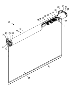
Fig. 1 is a schematic perspective view with partial removed elements
of a shading device 10 according to the present invention and shows the
shading device 10 assembled for normal operation. According to this
embodiment the shading device 10 is a roller blind. The shading device 10
comprises a winding core, more particularly a shade tube 11. The shade tube
11 is designed as a roller. On an outer surface 12 of the shade tube 11 a
shade
13 is attached. The shade 13 is made of a flexible material that can be rolled
up and rolled down the shade tube 11. A free end of the shade 13 has a bottom
rail 14 for stabilizing the shade 13 andlor operating the shade 13 by hand.
The shade tube 11 is hollow and has an inner surface 15 defining an
inner cavity 16. Within the inner cavity an end stop assembly 17 is arranged.
The end stop assembly 17 comprises a spindle 18, a first end stop 19 and a
second end stop 20. In this embodiment the first and second end stop 19, 20
are formed integrally with the spindle 18.
The end stop assembly 17 is mounted to an end piece 21. Here the
first end stop 19 is arranged adjacent to the end piece 21. The shade tube has
a
first tube end 22 and a second tube end 23. The end piece 21 is inserted in
the
inner cavity 16 of the shade tube 11 at the first tube end 22. The end piece
21
and the end stop assembly 17 are non-rotatable mounted to each other. A
bearing 24 is arranged at the end piece 21 connecting the end piece 21 with
the
inner surface 15 of the shade tube 11. Thus, the shade tube 11 is rotatable
relative to the end piece 21 and the end stop assembly 17.
CA 02876404 2015-01-06
14
A travelling nut 25 is moveably arranged on the spindle 18 between
the first and second end stop 19, 20. With an engaging element on the outer
surface the travelling nut 25 interacts with a complementary element 26 on
the inner surface 15 of the shade tube 11. In this embodiment the
complementary element 26 is designed as a bar extending parallel to the
longitudinal axis of the shade tube 11.
The first and second tube ends 22, 23 are respectively coupled to
first and second holding elements 27, 28. Each of the holding elements 27, 28
comprises a bracket 29 for mounting to a building structure. Furthermore,
holding element 27 assigned to the end piece 21 of the first tube end 22 has a
mounting disc 30. In this embodiment the mounting disc 30 comprises a drive
means for driving the shade tube 11. The mounting disc 30 has a stationary
recess which is non-rotatable fixed to the bracket 29 while the drive means of
the mounting disc 30 is rotatable relative to the recess. The end piece 21 has
a
stick which is also non-rotatable connected to the mounting disc 30, namely to
the recess of the mounting disc 30. Thus, the end stop assembly 17 is mounted
via the end piece 21 to the holding element 27.
The second tube end 23 has a stationary axle stub 31 extending out
of the inner cavity 16 of the shade tube 11. The axle stub 31 and the end
piece
21 forms a rotation axis of the shade tube 11 around the longitudinal centre
axis of the shade tube 11. The axle stub 31 is non-rotatable coupled to the
bracket 28 by an appropriate complementary mating formation 32. The axle
stub 31 is coupled by a further bearing 33 to the inner surface 15 of the
shade
tube 11. The further bearing 33 is inserted in the inner cavity 16 of the
shade
tube 11 at the second tube end 23. The bearing 33 allows rotation of the shade
tube 11 relative to the stationary axle stub 31.
Fig. 2 presents a schematic perspective view of a section with partial
removed elements of the shading device 10 according to Fig. 1. The spindle 18
is a threaded shaft. In this embodiment the spindle 18 is hollow to
accommodate an end of a stationary rod (not shown). This rod may be an
CA 02876404 2015-01-06
extension of axle stub 31 according to Fig. 1 or a rod of a counterbalancing
unit. The external thread of spindle 18 mates with the internal thread of
travelling nut 25.
The first and second end stops 19, 20 are forming end parts of the
5 spindle 18. Furthermore, the first and second end stops 19, 20 have a
greater
diameter than the spindle 18. Inner sides 34 of the first and second end stops
19, 20 have an abutment shoulder for contacting and stopping the travelling
nut 25 which has a complementary abutment shoulder.
The first and second end stops 19, 29 each have a mounting part 35
10 for mounting the end stop assembly 17 to a rod (not shown). In this
embodiment the mounting part 35 is designed as a bore for receiving a fixing
means like a screw, pin, bolt, etc. The mounting part 35 and/or fixing means
may interact with a rod (not shown) which is inserted in the hollow end stop
assembly 17 through one of the end stop openings 36. Accordingly, each end
15 stop opening 36 can serve as connector for connecting the end stop
assembly 17
to a stationary component of the shading device 10.
According to Fig. 2 the travelling nut 25 is arranged in a mid region
of the spindle between the first and second end stop 19, 20. Thus, the shade
tube 11 may be driven to roll up or unroll the shade 13.
Fig. 3 is a further schematic perspective view of a section with
partial removed elements of the shading device 10 according to the invention.
The travelling nut 25 interacts with the second end stop 20. More
particularly,
an abutment shoulder of the travelling nut 25 abuts a complementary
abutment shoulder at the inner side 34 of the second end stop 20. Thus, the
travelling nut 25 cannot be moved any further away from the first end stop 19.
This position of the travelling nut 25 corresponds to the lower end stop
position of the shade 13. In the lower end stop position of the shade 13, the
shade 13 cannot be unrolled any further of the shade tube 11. Only a rotation
of the shade tube 11 in an opposite direction to roll up the shade 13 is
possible.
CA 02876404 2015-01-06
16
Such a rotation of the shade tube 11 will move the travelling nut 25 along the
spindle 18 towards the first end stop 19.
Fig. 4 presents a schematic perspective view with partial removed
elements of a shading device 10 according to the present invention disengaged
from holding elements 27, 28. As in Fig. 3 the travelling nut 25 is contacting
the second end stop 20 and the shade 13 is in its lower end stop position. The
arrangement according to Fig. 4 shows the shading device 10 in a setting
position for setting or adjusting the lower end stop position of the shade 13.
The disengagement from the holding elements 27, 28 allows to roll up or unroll
the shade while rotating the shade tube 11 together with the end stop
assembly 17 without any relative movement of the spindle 18 or the travelling
nut 25 in regard to the shade tube 11. As a result the lower end stop position
of
the shade 13 is adjustable.
The holding element 27 has a fixing element 37. In this embodiment
the mounting disc 30 comprises the fixing element 37 which is stationary
coupled to the bracket 29. The fixing element 37 of the mounting disc 30 has
as
a recess for receiving and interacting with a correspondingly designed fixing
element (not shown) of the end piece 21 for realizing a stationary connection
of
the end piece 21 with the holding element 27.
The fixing element 37 of the holding element 27 and the respective
complementary fixing element of the end piece 21 have equidistantly and
coaxially distributed fixing means (not shown) to allow several different
orientations of the stationary end piece 21 relative to the stationary holding
element 27. When disengaged from the holding element 27 the end piece 21 is
rotatable to several discrete and equally distanced holding positions around a
centre axis of the mounting disc 30 in which the end piece 21 is connectable
to
the holding element 27.
Furthermore, the mounting disc 30 includes a drive unit in the form
of a drive wheel 59. The drive wheel 59 is rotatable mounted relative to the
fixing element 37 of the mounting disc 30. For normal operation the drive
CA 02876404 2015-01-06
17
wheel 59 is fixed to the shade tube 11 according to Fig. 1 to 3. A cord or
chain
(not shown) may be arranged to the drive wheel 59. By driving the drive wheel
59 via a cord or chain the shade tube 11 can be driven around the centre axis
of the shade tube 11 and the stationary end stop assembly 17.
Fig. 5 is a further schematic perspective view of a section with
partial removed elements of the shading device 10 according to the invention
with two travelling nuts 25, 38. First travelling nut 38 is assigned to the
first
end stop 19 for setting the upper end stop position of the shade 13. The
second
travelling nut 25 is assigned to the second end stop 20 for setting the lower
end
stop position of the shade 13. Both travelling nuts 25 and 38 are identically
designed. The distance between the first and second travelling nut 25, 38
defines the length of the shade 13 which can be rolled on or up rolled from
the
shade tube 11. The smaller the distance between the first and second
travelling nut 25, 38, the greater the windable length of the shade 13 is.
The second travelling nut 25 abuts according to Fig. 5 the second
end stop 20 like in Fig. 3. Thus, the travelling nut 25 cannot be moved any
further away from the first end stop 19. This position of the second
travelling
nut 25 corresponds to the lower end stop position of the shade 13. For
reaching
the upper end stop position of the shade 13, the shade tube 11 has to be
rotated such that both travelling nuts 25, 38 are moving towards the first end
stop 19. The upper end stop position of the shade 13 is reached when the first
travelling nut 38 abuts the first end stop 19.
Additionally Fig. 5 shows a rod 39, which has not been shown in Fig.
1 to 4 for clarity reasons, but which is also part of the embodiment of the
present invention according to Fig. 1 to 4 as well. The rod 39 is inserted
through end stop openings 36 into the hollow end stop assembly 17 and
through the hollow spindle 18. The end stop assembly 17 may be additionally
fixed to the rod 30 by the mounting parts 35. The rod 39 is stationary coupled
to the holding elements 27, 28. The rod 39 forms a stationary central axis of
the shading device 10 around which the shade tube 11 is rotatable in normal
CA 02876404 2015-01-06
18
operation of the shading device 10. In this embodiment the rod 39 is part of a
counterbalance unit.
Fig. 6 is an exploded view of a shading device 10 according to the
present invention. In this embodiment the end stop assembly 17 has two
travelling nuts 25, 38. In an alternative embodiment the end stop assembly 17
may have only a single travelling nut 25.
The shading device 10 comprises a counterbalance unit 40. The
counterbalance unit 40 serves for balancing the shade 13 in every desired
position of the shade 13.
The end piece 21 may be replaced by an alternative end piece 41.
The end pieces 21, 41 comprise a break device for slowing down or braking the
rotation of the shade tube 11. According to a further alternative end piece 21
may be replaced by an adapter, particularly in the form of end piece 41, but
without a break device. End pieces 21 and 41 both have a stationary fixing
element and a bearing 24.
Mounting unit 42 or 43 may be used as an alternative to mounting
disc 30. The mounting units 42, 43 are designed to be mounted on the inner
face of the brackets 29 like the mounting disc 30. In this embodiment the
mounting units 42, 43 are drive units configured to drive the shade tube 11.
For this purpose the mounting unit 43 has a cord 44. Pulling the cord 44
activates a drive means coupled with the shade tube 11. The mounting unit 42
needs an additional chain (not shown) to drive a drive means to rotate the
shade tube 11. The drive means of the mounting units 42, 43 are rotatable to a
stationary fixing element 37 of the mounting units 42, 43 which may be
similar to the fixing element 37 of the mounting disc 30.
Fig. 7 is an exploded view of the holding element 27 with the end
piece 21 for a shading device 10 according to the invention. In detail the
mounting disc 30 of the holding element 27 is shown in an exploded view. The
mounting disc 30 comprises the drive wheel 59, a bearing ring 60, the fixing
element 37 and a mounting cover 61.
CA 02876404 2015-01-06
,
19
A ball chain 62 is provided for arrangement around the drive wheel
59. The fixing element 37 has a mounting plate 63. The mounting plate 63 has
a tube like projection 64. The projection 64 provides a recess 65. The inner
side
of the recess 65 has several fixing means 66. For clarity not all fixing means
66
have a reference numeral. In this embodiment the fixing means 66 of the
fixing element 37 are formed as bars extending longitudinal to the projection
64.
For assembling the mounting disc 30 to the bracket 29 the mounting
cover 61 is arranged at the outer side of bracket 29. Then the fixing element
37
is coupled with its mounting plate 63 to the inner side of the bracket 29 and
coupled with the mounting cover 61. Thus, the fixing element 37 is stationary
mounted to the bracket 29. The drive wheel 59, ball chain 62 and bearing ring
60 form a drive unit which is attachable to the bracket 29 and the fixing
element 37. The drive wheel 59 is rotatable to the bearing ring 60 and the
fixing element 37.
Fig. 8 is a first perspective view of an assembled holding element 27
and the end piece 21 according to Fig. 7. By pulling at one side of ball chain
62
the ball chain 62 and the drive wheel 59 which is coupled with the ball chain
62 rotates around the fixing element 37. The drive wheel 59 has several
coupling members 67 for coupling the drive wheel 59 to the inner side of the
bearing 24 of end piece 21.
Fig. 9 is a second perspective view of the assembled holding
element 27 and the end piece 21 according to Fig. 8. The end piece 21 has a
fixing element 68. The fixing element 68 of end piece 21 is stationary. In
this
embodiment the fixing element 68 is formed as a stick. The fixing element 68
is surrounded by the bearing 24 which is rotatable around the fixing element
68. At the outer circumference of the fixing element 68 are several fixing
means 69. For clarity not all fixing means 69 have a reference numeral.
According to this embodiment the fixing means 69 are designed as grooves.
CA 02876404 2015-01-06
The fixing means 69 of the end piece 21 are complementary formed
to the fixing means 66 of the fixing element 37 of the holding element 27.
Fixing means 66 and 69 are equidistantly distributed around the centre axis of
the fixing element 37 and 68 respectively. Fixing element 68 of end piece 21
5 can be inserted into the recess 65 of the fixing element 37 to establish
a
stationary coupling between end piece 21 and the holding element 27. Because
of the several fixing means 66 and 69 several different holding positions of
the
end piece 21, namely the fixing element 68, relative to the holding element
21,
namely the fixing element 37, are realizable. Dependent of the amount of
10 fixing means 66, 69 the fixing element 68 is connectable with the fixing
element 37 in predetermined angle increments around the centre axis of the
end piece 21. This allows a precise adjustment of the lower and/or upper end
stop position of the shade 13.
The inner side of the bearing 24 has several coupling members 70
15 which are complementary to the coupling members 67 of the drive wheel
59.
By establishing the connection between both fixing elements 37 and 68 the
coupling members 67, 70 are also coupled with each other.
Fig. 10 is a schematic perspective view of an end stop assembly 17
for a shading device 10 according to the present invention with a travelling
nut
20 25 in an opened position. Travelling nuts 25 and 38 may (but need not)
be
identical. The following description of travelling nut 25 applies also to
travelling nut 38.
The travelling nut 25 is has articulated segments. More particularly,
it comprises two segments 45, 46 which are hingedly connected by a flexible
hinge 47. In this embodiment, the segments 45, 46 are designed as a first half
45 and a second half 46 respectively of the travelling nut 25. The flexible
hinge
47 allows to flip open the travelling nut 25 for arranging the travelling nut
25
around the spindle 18. The flexible hinge 47 is according to this embodiment
substantially made as a flexible plastic strip which is flexibly connected
with
the two halves 45, 46.
CA 02876404 2015-01-06
21
For engaging the travelling nut 25 around the spindle 18 the
travelling nut 25 is in its open position and half 45 is arranged to the
spindle
18 such that the external thread 48 of the spindle 18 mates with the internal
thread 49 of the half 45.
The first half 45 of the travelling nut 25 has a first joint element 50
and the second half 46 of the travelling nut 25 has a second joint element 51.
The joint elements 50, 51 are formed complementary to each other for realizing
an engagement with each other. By engaging both joint elements 50, 51 with
each other the two halves 45, 46 are connected to realize a closed position of
the travelling nut 25.
Fig. 11 is a schematic cross section of the end stop assembly 17 with
the travelling nut 25 in the opened position according to Fig. 10. According
to
this embodiment the first joint element 50 is designed as a snap-on catch and
the second joint element 51 is designed as a recess complementary formed to
the snap-on catch.
As the flexible hinge 47 is made as a flexible strip the two halves 45,
46 are displaced from each other in the opened position of the travelling nut
25. The flexible hinge 47 has several formations 52, 53 which mate with
complementary formed formations 54, 55 on the halves 45, 46 in a closed
position of the travelling nut 25.
The end stop openings 36 and the hollow spindle 18 have several
grooves 56 at the inner side of a tube section of the end stop assembly 17.
These grooves 56 mate with complementary formed bars of a rod 39 for
avoiding any rotation of the end stop assembly 17 relative to the rod 39.
Fig. 12 is a further schematic perspective view of the end stop
assembly 17 for the shading device 10 according to the present invention with
the travelling nut 25 in a closed position. In comparison to Fig. 11 the
travelling nut half 46 has been swung with the flexible hinge 47 around the
spindle 18 for coupling the nut halves 45, 46 with each other. In the closed
CA 02876404 2015-01-06
22
position of the travelling nut 25 the two halves 45, 46 form a ring shaped
travelling nut 25. The travelling nut 25 is moveably guided on the spindle 18.
Fig. 13 is a schematic cross section of the end stop assembly 17 with
the travelling nut 25 in the closed position according to Fig. 2. The snap-on
catch 50 is snapped on the correspondingly formed recess 51. Thus, the halves
45, 46 of the travelling nut 25 are detachable joined with each other.
The flexible hinge 47 is aligned to the travelling nut 25, whereby the
formations 52 and 53 engage the formations 54 and 55 respectively. An outer
surface 57 of the travelling nut 25 contacts the inner surface 15 of the inner
cavity 16 when the end stop assembly 17 with the closed travelling nut 25 is
inserted into the shade tube 11. In this case the connection between the two
halves 45, 46 cannot be unintentionally opened. The contact of the outer
surface 57 of the travelling nut 25 with the inner surface 15 of the inner
cavity
16 prevents a unintended opening of the travelling nut 25.
The outer surface 57 of the travelling nut 25 has engaging elements
58. In this embodiment the travelling nut 25 has two engaging elements 58
which are formed as grooves. The engaging elements 58 are assigned to the
first half 45 and the second half 46 respectively. When the end stop assembly
17 with the travelling nut 25 is inserted into the inner cavity 16 of the
shade
tube 11, the engaging elements 58 engage a complementary element in the
inner surface 15 of the shade tube. In this embodiment this complementary
element is formed as a bar 25 as shown in Fig. 1 to 5.
Although preferred embodiments of the present invention and
modifications thereof have been described in detail herein, it is to be
understood that this invention is not limited to these precise embodiments and
variations and may be effected by one skilled in the art without departing
from
the spirit and scope of the invention as defined by the appended claims.
The use of expressions like: "particularly", "preferably" or "especially
preferred" etc. is not intended to limit the invention. Features which are not
specifically or explicitly described or claimed may be additionally included
in
CA 02876404 2015-01-06
23
the structure or method according to the present invention without deviating
from its scope.