Note: Descriptions are shown in the official language in which they were submitted.
CA 02876572 2016-12-12
CARTON WITH ARTICLE PROTECTION INSERT
[0001]
[0002]
BACKGROUND OF THE DISCLOSURE
[0003] The present disclosure generally relates to cartons for holding
beverage containers or
other types of articles. More specifically, the present disclosure relates to
cartons having an article
protection insert and access features for positioning the article protection
insert.
SUMMARY OF THE DISCLOSURE
[0004] In general, one aspect of the disclosure is generally directed to
a carton for containing a
plurality of articles. The carton comprises a plurality of panels that extends
at least partially
around an interior of the carton, the plurality of panels comprising a top
panel, a bottom panel, a
first side panel, and a second side panel. An article protection insert
comprises a plurality of
features for engaging a respective article of the plurality of articles. At
least one access feature
is in the top panel for positioning the article protection insert to a
position wherein the features
engage at least one article of the plurality of articles.
- 1 -
CA 02876572 2014-12-12
WO 2014/014513
PCT/US2013/031886
[0005] In
another aspect, the disclosure is generally directed to a combination of a
carton blank
and an article protection insert blank for forming a carton for containing a
plurality of articles.
The carton blank comprises a plurality of panels comprising a top panel, a
bottom panel, a first
side panel, and a second side panel, and at least one access feature in the
top panel for
positioning the article protection insert blank. The article protection insert
blank comprises a
plurality of features for engaging a respective article of the plurality of
articles. The at least one
access feature is for positioning the article protection insert to a position
wherein the features
engage at least one article of the plurality of articles in the carton formed
from carton blank and
the article protection insert blank.
[0006] In
another aspect, the disclosure is generally directed to a method of forming a
carton.
The method comprises obtaining a carton blank comprising a plurality of panels
comprising a
top panel, a bottom panel, a first side panel, and a second side panel, and at
least one access
feature in the top panel. The method comprises obtaining an article protection
insert blank
comprising a plurality of features for engaging a respective article of the
plurality of articles and
positioning the article protection insert blank relative to the carton blank.
The method
comprises forming an interior of the carton at least partially defined by the
plurality of panels,
the forming the interior of the carton comprising forming an open-ended
sleeve, loading a
plurality of articles in the interior of the carton, and accessing the article
protection insert blank
through the at least one access feature to form the article protection insert
with the features in
engagement with a respective article of the plurality of articles.
[0007] Other
aspects, features, and details of the present disclosure can be more
completely
understood by reference to the following detailed description of exemplary
embodiments taken
in conjunction with the drawings and from the appended claims.
BRIEF DESCRIPTION OF THE DRAWINGS
[0008] Those
skilled in the art will appreciate the above stated advantages and other
advantages
and benefits of various additional embodiments reading the following detailed
description of the
embodiments with reference to the below-listed drawing figures. Further, the
various features of
the drawings discussed below are not necessarily drawn to scale. Dimensions of
various
features and elements in the drawings may be expanded or reduced to more
clearly illustrate the
embodiments of the disclosure.
-2-
CA 02876572 2014-12-12
WO 2014/014513
PCT/US2013/031886
[0009] Fig. 1 is a plan view of an exterior surface of a carton blank
according to a first
exemplary embodiment of the disclosure.
100101 Fig. 2 is a plan view of an exterior surface of an article
protection insert blank according
to the first exemplary embodiment of the disclosure.
[0011] Fig. 3 is a perspective view of an assembled carton according to the
first exemplary
embodiment of the disclosure.
[0012] Fig. 4 is a bottom perspective view of the assembled carton of Fig.
3.
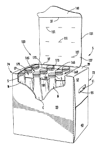
[0013] Fig. 5 is a side schematic view of the carton of Fig. 3 with a
carton forming machine
positioning an article protection insert to a first position.
[0014] Fig. 6 is a side schematic view of the carton with a carton forming
machine positioning
an article protection insert to a second position.
[0015] Fig. 7 is a perspective view similar to Fig. 3 with a dispenser in
an open position.
[0016] Fig. 8 is a perspective view similar to Fig. 7 showing an article
protection insert
removed to allow access to articles in the carton.
[0017] Fig. 9 is a plan view of an exterior surface of a carton blank
according to a second
exemplary embodiment of the disclosure.
[0018] Fig. 10 is a plan view of an exterior surface of an article
protection insert blank
according to the second exemplary embodiment of the disclosure.
[0019] Fig. 11 is side perspective view of the assembled carton of the
second embodiment with
a portion of the carton removed to show an interior of the carton with the
article protection
insert in a first position.
[0020] Fig. 12 is side perspective view of a portion of the assembled
carton of the second
embodiment with a portion of the carton removed to show an interior of the
carton with the
article protection insert in a second position.
[0021] Fig. 13 is a schematic view of a carton with an article protection
insert of a third
exemplary embodiment of the disclosure.
[0022] Fig. 14 is a plan view of an exterior surface of an article
protection insert blank of the
third exemplary embodiment.
-3-
CA 02876572 2014-12-12
WO 2014/014513
PCT/US2013/031886
[0023] Fig.
15 is a plan view of an exterior surface of an article protection insert blank
of an
alternative embodiment.
100241 Fig.
16 is a plan view of an exterior surface of an article protection insert blank
of an
alternative embodiment.
[0025] Fig.
17 is a detailed perspective view of an article protection insert formed form
the
article protection insert blank of Fig. 16 attached to a row of articles.
[0026] Fig.
18 is a plan view of an exterior surface of an article protection insert blank
of an
alternative embodiment.
[0027] Fig.
19 is a schematic cross-section showing an article protection insert formed
from the
article protection insert blank of Fig. 18 attached to a group of articles.
[0028] Fig.
20 is a perspective view of the article protection insert of Fig. 19 removed
from the
group of articles.
[0029] Fig.
21 is a top perspective view of a portion of a carton having the article
protection
insert of Fig. 19 attached to a group of articles.
[0030] Fig.
22 is a plan view of an exterior surface of a carton blank of a fourth
exemplary
embodiment of the disclosure.
[0031] Fig.
23 is a plan view of an exterior surface of an article protection insert blank
of the
fourth exemplary embodiment of the disclosure.
[00321 Figs.
24 and 25 are top perspective views of the carton of the fourth exemplary
embodiment of the disclosure with the article protection insert formed from
the article protection
insert blank of Fig. 23.
[0033]
Corresponding parts are designated by corresponding reference numbers
throughout the
drawings.
DETAILED DESCRIPTION OF THE EXEMPLARY EMBODIMENTS
100341 The
present disclosure generally relates to protection, opening, dispensing, and
handling
features for cartons that contain articles such as containers, bottles, cans,
etc. The articles can be
used for packaging food and beverage products, for example. The articles can
be made from
materials suitable in composition for packaging the particular food or
beverage item, and the
materials include, but are not limited to, glass; aluminum and/or other
metals; plastics such as
-4-
CA 02876572 2016-12-12
PET, LDPE, LLDPE, HDPE, PP, PS, PVC, EVOH, and Nylon; and the like, or any
combination
thereof.
[0035] Some of the various features disclosed may be similar to any of
the embodiments
disclosed in U.S. Patent Application No. 13/419,740, (which issued under U.S.
Patent No.
9,284,084, March 15, 2016) and all related applications. Further, some of the
various features
disclosed herein may be combined with features disclosed in the '084 patent to
restrain movement
of the containers in the carton.
100361 Cartons according to the present disclosure can accommodate
articles of any shape. For
the purpose of illustration and not for the purpose of limiting the scope of
the disclosure, the
following detailed description describes beverage containers (e.g., glass
beverage bottles) as
disposed within the carton embodiments. In this specification, the terms
"lower," "bottom,"
"upper" and "top" indicate orientations determined in relation to fully
erected and upright
cartons.
[0037] Fig. 1 is a plan view of the exterior side 1 of a blank, generally
indicated at 3, used to
form a carton 5 (Fig. 3) according to a first exemplary embodiment of the
disclosure. The
carton 5 can be used to house a plurality of articles such as containers C
(Fig. 5). In the
illustrated embodiment, the containers C are bottles having a wide bottom
portion BP, an upper
portion or neck N extending upwardly from the bottom portion BP, a cap CP at
the top of each
container C, and a shoulder S just below the cap. In the illustrated
embodiment, the carton 5 is
sized to house twelve containers C in a single layer in a 3x4 arrangement, but
it is understood that
the carton 5 may be sized and shaped to hold containers C of a different or
same quantity in
more than one layer and/or in different row/column arrangements (e.g., 1x6,
3x6, 2x6, 2x6x2,
3x4x2, 2x9, 4x3, etc.). The containers C could be otherwise shaped, arranged,
and/or
configured without departing from the disclosure. For example, the containers
C could be
beverage cans or other containers. In the illustrated embodiment, the carton 5
includes a handle,
generally indicated at 11 (Fig. 3), for grasping and carrying the carton.
[0038] The blank 3 has a longitudinal axis L1 and a lateral axis L2. In
the illustrated
embodiment, the blank 3 comprises a bottom panel 15 foldably connected to a
first side panel 17
at a first lateral fold line 19, a second side panel 23 foldably connected to
the bottom panel 15 at
a second lateral fold line 25, and a top panel 29 foldably connected to the
second side panel 23
at a third lateral fold line 31. In one embodiment, an adhesive flap 33 is
foldably connected to
the top panel 29 at a fourth lateral fold line 37.
- 5 -
CA 02876572 2016-12-12
[0039] The bottom panel 15 is foldably connected to a first bottom end
flap 43 and a second
bottom end flap 45. The first side panel 17 is foldably connected to a first
side end flap 47 and a
second side end flap 49. The second side panel 23 is foldably connected to a
first side end flap
53 and a second side end flap 55. The top panel 29 is foldably connected to a
first top end flap
57 and a second top end flap 59. When the carton 5 is erected, the end flaps
43, 47, 53, 57 close
a first end 72 of the carton, and the end flaps 45, 49, 55, 59, close a second
end 74 of the carton.
In accordance with an alternative embodiment of the present disclosure,
different flap
arrangements can be used for closing the ends of the carton 5.
[0040] The end flaps 43, 47, 53, 57 extend along a first marginal area of
the blank 3, and are
foldably connected at a first longitudinal fold line 67 that extends along the
length of the blank.
The end flaps 45, 49, 55, 59 extend along a second marginal area of the blank
3, and are
foldably connected at a second longitudinal fold line 69 that also extends
along the length of the
blank. The longitudinal fold lines 67, 69 may be, for example, substantially
straight, or offset at
one or more locations to account for blank thickness or for other factors
without departing from
the scope of the disclosure.
[0041] As shown in Fig. 1, the blank 3 has handle features for forming a
handle 11 at each end
72, 74 of the carton 5. The handle features include handle flaps 95 foldably
connected to a
respective top end flap 57, 59, and notches or openings 97 in the side end
flaps 53, 55, 47, 49.
The openings 97 cooperate to provide an opening at a respective closed end 72,
74 to allow a
respective handle flap 95 to be inwardly folded so that the carton 5 can be
grasped at a
respective end. The blank 3 can have other features for forming the handle 11,
or the blank
and/or carton can have a handle that is alternatively shaped, arranged, and/or
configured without
departing from the disclosure. Further, the handle 11 can be omitted without
departing from the
disclosure.
[0042] In one embodiment, the blank 3 has features for forming article
protection features in
the ends 72, 74 of the carton 5. As shown in Fig. 1, the side end flaps 47,
49, 53, 55 have
deformations in the form of indentations 105 on the exterior surface 1 of the
blank 3 such that
the indentations form a protrusion on the interior surface of the blank. The
bottom end flaps 43,
45 each have two rows of deformations in the form of indentations 107 on the
interior surface of
the blank 3 such that the indentations on the interior surface form a
protrusion on the exterior
surface 1 of the blank 3. As shown in Fig. 1, the top end flaps 57, 59 each
have a respective distal
edge 111 having corner notches 113 and a center notch 115. The indentations
105, 107
can be any deformation on a surface of a respective side end flaps 47, 49, 53,
55 or bottom end
flap 43, 45 such that the deformation can be any suitable shape (e.g., a
concave depression or
protrusion, convex depression or protrusion, flat depression or protrusion,
embossed area,
- 6 -
CA 02876572 2016-12-12
debossed area, etc., or any other suitable shape). Furthermore, the
indentations 105, 107 could
be formed on the interior or exterior surface of one or more of the first side
panel 17, second
side panel 23, top panel 29, bottom panel 15, or top end flaps 57, 59 without
departing from the
disclosure. The blank 3 can have other protection features that are
alternatively shaped,
arranged, and/or configured without departing from the disclosure. Further,
the indentations 105,
107 can be omitted without departing from the disclosure.
100431 In the illustrated embodiment, the blank 3 includes three bottom
article protection flaps
121 arranged in a 1x3 arrangement and foldably connected to the bottom panel
15, but the blank
3 could have more or less than three bottom article protection flaps 121, and
the flaps 121 could
be otherwise arranged in other suitable row/column arrangements or in a random
configuration
on the bottom panel 15, including a multiple row or a multiple column
configuration, or any
other suitable configuration. The bottom article protection flaps 121 are each
foldably connected
to the bottom panel 15 at a respective lateral fold line 123 and are each at
least partially defined
by a line of weakening 125 in the bottom panel 15. In one embodiment, the line
of weakening
125 is a cut, but the line of weakening could comprise other forms of
weakening (e.g., a tear line
that comprises cut lines separated by breakable nicks, a tear line that is
formed by a series of
spaced apart cuts, etc.) that allow the bottom article protection flap 121 to
separate from the
bottom panel 15 without departing from the disclosure. In other embodiments,
the blank 3 can
include bottom article protection flaps 121 that are otherwise, shaped,
arranged, and/or
configured without departing from the disclosure. The bottom article
protection flaps 121 could
be omitted without departing from the disclosure.
[0044] In one embodiment, the blank 3 comprise a dispenser panel 131 in
the top panel 29 and
the second side panel 23 for forming a dispenser 133 in the carton 5. The
dispenser panel 131 is
formed by a dispenser pattern or tear line 135 that extends from the lateral
fold line 37, across
the top panel 29, and into a portion of the second side panel 23. In one
embodiment, the
dispenser panel 131 comprises a first portion 137 in the top panel 29 and a
second portion 141
foldably connected to the first portion at a portion of the lateral fold line
3 1 extending across the
dispenser panel 131. As shown in Figs. 3, 7, and 8, the second portion 141 of
the dispenser panel
131 forms an access flap for grasping and initiating separation of the
dispenser panel from
the carton 5 to create the dispenser opening 145 for accessing the containers
C. The dispenser
panel 131 could be otherwise shaped, arranged, and/or configured without
departing from the
disclosure. Further, the dispenser 133 and the dispenser panel 131 could be
omitted without
departing from the disclosure.
- 7 -
CA 02876572 2014-12-12
WO 2014/014513
PCT/US2013/031886
[0045] As
shown in Fig. 1, the top panel 29 includes nine access features 151 in the
form of
cuts arranged in a 3x3 arrangement with three cuts in each row and column. The
access features
151 could be openings in the top panel 29 or the access features could
comprises flaps foldably
connected to the top panel to create an access opening when folded relative to
the top panel.
Further, there could be more or less than nine access features 151 in the top
panel or the access
features could be otherwise shaped, arranged, and/or configured without
departing from the
disclosure. The access features 151 are for receiving a respective actuator or
finger 155 of a
carton forming machine 157 (Figs. 5 and 6). In one embodiment, the access
features 151 are
provided in the dispenser panel 131. The access features 151 could be
otherwise shaped,
arranged, positioned, and/or configured without departing from the disclosure.
[0046] As
shown in Fig. 2, an article protection insert blank 163 is shown for forming
an article
protection insert 165 (Fig. 7) in the carton 5. In one embodiment, the article
protection insert
blank 163 can include features for engaging the articles C that include two
central openings 166
and two notches 167 in a middle portion 169 of the article protection insert
blank. The article
protection insert blank 163 includes a first outer portion 171 that has four
notches 173 at a distal
edge 172 of the article protection insert blank. The article protection insert
blank 163 includes a
second outer portion 179 that is shaped similar to the first outer portion 171
and has four
notches 181 at a distal edge 183 of the article protection insert blank. As
shown in Figs. 5 and
7, the features of the article protection insert 165 for engaging the articles
C can include the
openings 166 and notches 167, 173, 181. In the embodiment of Figs. 6 and 7,
the article
protection insert 165 is positioned so that the features 166, 167, 173, 181
engage a respective
container below the shoulder S of each container C such that the insert
engages an underside of
the shoulder to restrain the movement of the containers C in the carton 5. In
the embodiment of
Fig. 5, the article protection insert 165 is positioned so that the features
166, 167, 173, 181
engage a respective container C below the cap CP of each container such that
the insert engages
an underside of the cap CP to restrain the movement of the containers C in the
carton. The
article protection insert 165 could be otherwise shaped, arranged, configured,
and/or positioned
such as to engage other portions of the containers C (e.g., the neck N)
without departing from
the disclosure. The features 166, 167, 173, 181 of the article protection
insert 165 could
comprise retention flaps or other features for engaging the containers C. The
article protection
insert 165 and the article protection insert blank 163 could be otherwise
shaped, arranged,
and/or configured or could have other features without departing from the
disclosure.
-8-
CA 02876572 2014-12-12
WO 2014/014513
PCT/US2013/031886
[0047] In
accordance with one exemplary embodiment, the carton can be formed from the
carton blank 3 and the article protection insert blank 163 by attaching the
article protection
insert blank to the top panel 29 by glue or other adhesive. The attachment of
the article
protection insert blank 163 to the carton blank 3 is a temporary attachment as
the article
protection insert blank can be secured to the top panel 29 by releasable
adhesive such as glue or
other suitable adhesive. Further, at various stages of the erecting process,
glue or other adhesive
can be applied to various portions of the blank 3. After attaching the article
protection insert
blank 163 to the top panel 29, the combined blanks 3, 163 can be formed into
an open-ended
sleeve by folding the bottom panel 15, side panels 17, 23, and top panel 29
along respective fold
lines 19, 25, 31, 37. Containers C can be loaded into an interior space of the
sleeve. One of the
ends 72, 74 can be closed prior to loading the containers C or both of the
ends can be closed
after loading the containers into the interior space.
[0048] After
closing the ends 72, 74 (or alternatively, prior to closing the ends), the
article
protection insert 165 can be positioned to engage the articles C. As shown in
Figs. 5 and 6, a
carton forming machine 157 having fingers or actuators 155 can be used to
separate the article
protection insert 165 from the top panel 29 and position the article
protection insert 165 on the
articles C. The actuators 155 of the carton forming machine 157 are inserted
through the access
features 151 in the top panel 29 to contact the article protection insert 165.
In one embodiment,
the carton forming machine 157 has a total of nine actuators 155 arranged in a
3x3 configuration
with a respective row of three actuators respectively contacting the middle
portion 169, the first
outer portion 171, and the second outer portion 179. The carton forming
machine 157 could
have more or less than nine actuators 155 or the actuators could be otherwise
shaped, arranged,
and/or configured without departing from the disclosure. In the illustrated
embodiment, the
actuators 155 press down on the article protection insert 165 by way of the
access features or
cuts 151 in the top panel 29. When the article protection insert 165 is
contacted by the
actuators, the article protection insert breaks the adhesive bond with the top
panel 29 and
separates from the top panel such that the carton forming machine 157
positions the article
protection insert to be generally parallel and spaced apart from the top panel
29. In the
embodiment of Fig. 5, the article protection insert 165 is positioned so that
the features 166,
167, 173, 181 of the article protection insert engage the underside of a cap
CP of a respective
container C. In the embodiment of Fig. 6, the article protection insert 165 is
positioned so that
the features 166, 167, 173, 181 of the article protection insert engage the
shoulder S or the
underside of the shoulder. Alternatively, one or more of the notches 173, 181
could engage an
underside of the shoulder S of a respective container C in the carton 5 and
the openings 166
and/or notches 167 could engage the underside of the cap CP of a respective
container in the
carton. Further, one or more of the notches 173, 181 could engage an underside
of a cap CP of
-9-
CA 02876572 2016-12-12
a respective container C in the carton 5 with one or more of the openings 166
and/or notches
167 engaging an underside of the shoulder S of a respective container in the
carton 5. Also, the
article protection insert 165 could be positioned so that one or more of the
features 166, 167,
173, 181 engages the neck N of the respective containers in the carton 5. The
article protection
insert 165 is positioned to engage a top portion of the containers C in the
carton 5 to prevent or
reduce the movement of the containers in the carton and to prevent or reduce
breakage of the
containers articles. The article protection insert 165 could be otherwise
positioned in the carton
without departing from the disclosure.
[0049] In one embodiment, the loaded and closed carton 5 is further
processed so that the
bottom article protection flaps 121 are activated to provide a cushion between
the bottom
portions BP of the containers C inside the carton and further secure the
containers to prevent
breaking. The bottom article protection flaps 121 are foldably connected to
the bottom panel 15
and moveable between a first position (that is substantially parallel to the
bottom panel) and a
second position (Fig. 4) wherein the bottom article protection flaps are
folded upwardly relative
to the bottom panel 15. In one embodiment, the bottom article protection flaps
121 are raised or
activated and the bottom article protection flaps have features for preventing
the folding of the
article protection flaps from the second position back to the first position.
It is understood that
the bottom article protection flaps 121 will be activated to the second
position (Fig. 4) after the
ends 72, 74 of the carton 5 have been closed. Alternatively, the bottom
article protection
flaps 121 could be activated prior to closing one or both of the ends 72, 74
of the carton 5
without departing from the disclosure. In one embodiment, the bottom article
protection flaps
121 are in contact with the bottom portion BP of the containers C, and the
article protection
insert 165 is in contact with the top portion of the containers (e.g., neck N,
cap CP, or shoulder
S) to prevent or reduce the movement of the containers C in the carton 5 and
to prevent or
reduce breakage of the containers or other articles. The carton 5 and article
protection insert
165 could be formed by other different steps, processes, or features without
departing from the
disclosure.
[0050] Figs. 9-12 illustrate various features of a carton blank 203 and
an article protection
insert blank 208 for forming a carton 205 having an article protection insert
210 of a second
embodiment, the second embodiment having similar features as the first
embodiment of the
disclosure. Accordingly, similar or identical features of the embodiments are
provided with like
or similar reference numbers. As shown in Fig. 9, the carton blank 203 is
similar to the carton
blank 3 of Fig. 1, except the carton blank 203 does not have a dispenser panel
131 forming the
dispenser 133 of the first embodiment. As shown in Fig. 10, the article
protection insert blank
208 comprises a middle portion 211 having arcuate openings 213 with tabs 215
having a curved
- 10 -
CA 02876572 2014-12-12
WO 2014/014513
PCT/US2013/031886
edge 217 adjacent each opening 213. In one embodiment, the middle portion 211
comprises
fold lines 221 extending between adjacent arcuate openings 213 across the
width of the article
protection insert blank 208. The article protection insert blank 208 comprises
a first outer
portion 223 and a second outer portion 225 that are respectively foldably
connected to the
middle portion 211 at respective fold lines 227, 229 that are adjacent
respective arcuate
openings 213. A first foldable portion 231 of the middle portion 211 is formed
between
respective fold lines 221 and 227 and a second foldable portion 233 of the
middle portion is
formed between the respective fold lines 221 and 229. In one embodiment, the
article
protection insert blank 208 includes a strip 237 of adhesive such as
releasable adhesive for
temporarily attaching the article protection insert blank to the top panel 29.
One or more strips
of adhesive 237 could be provided, or the article protection insert blank 208
could be attached
to the carton blank 203 by other means.
[0051] In
one embodiment, each of the first outer portion 223 and the second outer
portion 225
has respective notches 241, 243 in a respective outer edge 245, 247 of the
article protection
insert blank 208. Each of the first outer portion 223 and the second outer
portion 225 has a
respective projection 251, 253 between respective adjacent notches 241, 243.
The article
protection insert blank 208 and the article protection insert 210 could be
otherwise shaped,
arranged, and/or configured without departing from the disclosure.
[0052] As
shown in Fig. 11 the article protection insert blank 208 can be positioned to
form the
article protection insert 210 by the carton forming machine 157 to retain the
articles C in a
similar manner as the article protection insert 165 of the first embodiment.
In one embodiment,
the middle portion 211 of the article protection insert 210 is in face-to-face
contact with the
interior surface of the top panel 29 with the tabs 215 in contact with a top
surface of the caps CP
of the containers C in the two middle rows. In the embodiment of Fig. 11, the
two outer
portions 223, 225 of the article protection insert 210 can be pushed downward
to extend
downwardly from the middle portion 211 so that the notches 241, 243 engage a
respective neck
N of the containers C in the two outer rows. The edges of the middle portion
211 adjacent the
arcuate openings 213 can engage the shoulders S, the underside of the caps C,
or the necks N of
the containers C in the two middle rows without departing from the disclosure.
As shown in
Figs. 11 and 12, at least a portion of the caps CP of the containers C in the
two middle rows
extend through the arcuate openings 213 with the foldable portions 231, 233
extending
obliquely from the tabs 215 that are in face-to-face contact with the top
panel 29 of the carton 5
and the caps CP of the containers C. In the embodiment of Fig. 12, the middle
portion 211 of
the article protection insert 210 is arranged similar to the positioning shown
in Fig. 11. As
shown in Fig. 12, the two outer portions 223, 225 of the article protection
insert 210 engage the
-11-
CA 02876572 2014-12-12
WO 2014/014513
PCT/US2013/031886
underside of a respective cap CP of the containers C of the two outer rows.
The article
protection insert 210 could be otherwise shaped, arranged, and/or configured
without departing
from the disclosure.
100531 Figs.
13 and 14 show an alternative embodiment of a carton 305 having an article
protection insert 310 formed from an article protection insert blank 312. The
outline of the
carton 305 is shown in Fig. 13 to give an approximation of some of the
features of one
embodiment of a carton, but the article protection insert 310 could be used
with any other
suitable carton design without departing from the disclosure. In the
embodiment of Figs. 13 and
14, the article protection insert 310 has a top panel 313, a first side panel
315 foldably
connected to the top panel at a fold line 317, and a second side panel 319
foldably connected to
the top panel at a fold line 321. In one embodiment, the top panel 313 has
openings 325 for
receiving a neck N of a respective container C in the carton 305. In one
embodiment, each of
the side panels 315, 319 has a respective upper portion 331, 333 foldably
connected to a
respective lower portion 335, 337 at a respective fold line 341, 343.
[0054] As
shown in Fig. 13, the article protection insert 310 is formed so that the
necks N of
the containers C of a row of containers are received in respective opening 325
in the top panel
313. The first side panel 315 is folded with respect to the top panel 313 and
extends
downwardly from the top panel 313 and is between an adjacent row of containers
C loaded in
the carton 305. Similarly, the second side panel 319 is folded with respect to
the top panel 313
and extends downwardly from the top panel 313 and is between an adjacent row
or containers C
loaded in the carton 305.
[0055] Fig.
15 shows an alternative article protection insert blank 412 similar to the
article
protection insert blank 312 of the previous embodiment. The article protection
insert blank 412
is longer and includes six openings 325 in the top panel to accommodate a row
of six containers.
[0056] Figs.
16 and 17 show an alternative article protection insert blank 452 for forming
an
article protection insert 454 similar to the article protection insert blank
312 and article
protection insert 310 of the embodiment of Figs. 13 and 14. The article
protection insert blank
452 includes article protection flaps 458 foldably connected to the first side
panel 315 and
article protection flaps 460 foldably connected to the second side panel 319.
The article
protection flaps 458, 460 are respectively foldably connected to one of the
first side panel 315
and the second side panel 319 at a respective fold line 464, 466. In one
embodiment, the article
protection flaps 458, 460 are at least partially defined by a respective cut
470, 472 extending
from a respective fold line 464, 466. As shown in Fig. 17, the article
protection flaps 458, 460
are moveable between a first position substantially parallel to a respective
first side panel 315
-12-
CA 02876572 2014-12-12
WO 2014/014513
PCT/US2013/031886
and a respective second side panel 319 and a second position wherein the
article protection flaps
are outwardly folded relative to the side panels and positioned for placement
between containers
of an adjacent row of containers.
[0057] Figs.
1 8-2 1 show an alternative article protection insert blank 502 for forming an
article
protection insert 504 in a carton 505 having similar features as the article
protection insert blank
163 and article protection insert 165 of the first embodiment. In the
embodiment of Figs. 18-21,
the article protection insert 504 has a middle portion 510 having openings 512
and two outer
portions 514, 516 having respective notches 520, 522. In one embodiment, the
middle portion
510 comprises fold lines 524 between or adjacent respective openings 512. As
shown in Fig.
21, the openings 512 in the middle portion 510 receive a respective neck N of
a middle row of
containers C and contacts a portion of the containers in the middle row below
the shoulder S of
the containers C to restrain movement of the containers in the carton. The
notches 520, 522 in a
respective outer portion 514, 516 of the article protection insert 504 can
contact an underside of
the cap CP of the containers (Fig. 21) in the two outer rows to restrain
movement of the
containers C in the carton, or the notches 520, 522 can contact the shoulders
S of the containers
C (Fig. 19) without departing from the disclosure.
[0058] Figs.
22-25 show a fourth embodiment of a carton blank 601 and article protection
insert blank 603 for forming a carton 605 with an article protection insert
607 similar to the
previous embodiments. The carton blank 601 is similar to the carton blank 3 of
the first
embodiment and like or similar features are indicated with like or similar
reference numbers. In
the embodiment of Fig. 22, the carton blank 601 includes handle reinforcement
flaps 611
foldably connected to a respective side end flap 47, 49, 53, 55 for
reinforcing the handle 11 in a
respective end 72, 74 of the carton 605. The carton blank 601 could have other
features or the
features shown could be otherwise shaped, arranged, configured, and/or omitted
without
departing from the disclosure.
[0059] Fig.
23 shows the article protection insert blank 603 that has a middle portion 621
having two openings 625 and two notches 627 and two outer portions 631, 633
having
respective notches 635, 637. As shown in Figs. 24 and 25, the openings 625 and
notches 627
in the middle portion 621 of the article protection insert 607 receive a
respective neck N of the
containers in the middle row and the notches 635, 637 of a respective outer
portion 631, 633
engage a respective container C in the outer two rows of containers such that
the outer portions
engage the underside of a cap CP of the containers. The article protection
insert 607 has
protruding portions 611, 613 between respective adjacent notches 635, 637. The
article
protection insert 607 could be otherwise shaped, arranged, configured, and
could have other
-13-
CA 02876572 2014-12-12
WO 2014/014513
PCT/US2013/031886
features without departing from the disclosure. Further, the article
protection insert 607 could
be used with a carton blank other than the blank 601 without departing from
the disclosure.
100601 In
general, the blank may be constructed from paperboard having a caliper so that
it is
heavier and more rigid than ordinary paper. The blank can also be constructed
of other
materials, such as cardboard, or any other material having properties suitable
for enabling the
carton to function at least generally as described above. The blank can be
coated with, for
example, a clay coating. The clay coating may then be printed over with
product, advertising,
and other information or images. The blank may then be coated with a varnish
to protect
information printed on the blanks. The blank may also be coated with, for
example, a moisture
barrier layer, on either or both sides of the blanks. The blank can also be
laminated to or coated
with one or more sheet-like materials at selected panels or panel sections.
[0061] As an
example, a tear line can include: a slit that extends partially into the
material
along the desired line of weakness, and/or a series of spaced apart slits that
extend partially into
and/or completely through the material along the desired line of weakness, or
various
combinations of these features. As a more specific example, one type tear line
is in the form of
a series of spaced apart slits that extend completely through the material,
with adjacent slits
being spaced apart slightly so that a nick (e.g., a small somewhat bridging-
like piece of the
material) is defined between the adjacent slits for typically temporarily
connecting the material
across the tear line. The nicks are broken during tearing along the tear line.
The nicks typically
are a relatively small percentage of the tear line, and alternatively the
nicks can be omitted from
or torn in a tear line such that the tear line is a continuous cut line. That
is, it is within the scope
of the present disclosure for each of the tear lines to be replaced with a
continuous slit, or the
like. For example, a cut line can be a continuous slit or could be wider than
a slit without
departing from the present disclosure.
[0062] In
accordance with the exemplary embodiments, a fold line can be any
substantially
linear, although not necessarily straight, form of weakening that facilitates
folding therealong.
More specifically, but not for the purpose of narrowing the scope of the
present disclosure, fold
lines include: a score line, such as lines formed with a blunt scoring knife,
or the like, which
creates a crushed or depressed portion in the material along the desired line
of weakness; a cut
that extends partially into a material along the desired line of weakness,
and/or a series of cuts
that extend partially into and/or completely through the material along the
desired line of
weakness; and various combinations of these features. In situations where
cutting is used to
create a fold line, typically the cutting will not be overly extensive in a
manner that might cause
a reasonable user to incorrectly consider the fold line to be a tear line.
-14-
CA 02876572 2014-12-12
WO 2014/014513
PCT/US2013/031886
[0063] The
above embodiments may be described as having one or more panels adhered
together by glue during erection of the carton embodiments. The term "glue" is
intended to
encompass all manner of adhesives commonly used to secure carton panels in
place.
[0064] The
foregoing description of the disclosure illustrates and describes various
exemplary
embodiments. Various additions, modifications, changes, etc., could be made to
the exemplary
embodiments without departing from the spirit and scope of the disclosure. It
is intended that all
matter contained in the above description or shown in the accompanying
drawings shall be
interpreted as illustrative and not in a limiting sense. Additionally, the
disclosure shows and
describes only selected embodiments of the disclosure, but the disclosure is
capable of use in
various other combinations, modifications, and environments and is capable of
changes or
modifications within the scope of the inventive concept as expressed herein,
commensurate with
the above teachings, and/or within the skill or knowledge of the relevant art.
Furthermore,
certain features and characteristics of each embodiment may be selectively
interchanged and
applied to other illustrated and non-illustrated embodiments of the
disclosure.
-15-