Note: Descriptions are shown in the official language in which they were submitted.
ICE HOCKEY PRACTICE TARGET
FIELD
[0001] The disclosure relates generally to the field of sports in which a
netted goal is used for
scoring, and more specifically, to the sport of ice hockey.
BACKGROUND
[0002] Ice hockey, and other like sports, is a competitive game in which an
object such as a puck is
shot through the opening of a netted goal. Because the goal is defended, the
ability to control the
accuracy and speed of the shot are valuable skills for an offensive player.
Therefore, the ability to
master these skills during training can improve the player's game performance,
resulting in more
goals. Players can practice these skills with targets placed in the upper and
lower corners of the goal
opening or with inserts which fit within the goal opening, manufactured with
strategically placed
holes/slots or in the form of a goalie.
SUMMARY
[0003] The subject matter of this application may involve, in some cases,
interrelated products,
alternative solutions to a particular problem, and/or a plurality of different
uses of a single system or
article.
[0004] According to a broad aspect, there is provided a hockey practice target
to be used with a
hockey goal, the hockey goal having a single horizontal crossbar connecting a
first goal post and a
second goal post, the ice hockey practice target comprising: a base; a first
substantially tubular
portion comprising metal, the first substantially tubular portion comprising a
first end attached to
the base and a yoke shaped second end adapted to receive the horizontal
crossbar; and a second
tubular portion mounted to the base, the second tubular portion being parallel
to the first
substantially tubular portion, being shorter than the first substantially
tubular portion, and having an
outer diameter that is less than the inner diameter of the first goal post and
less than the outer
diameter of the first substantially tubular portion, the second tubular
portion being adapted to
1
Date Recue/Date Received 2020-06-05
engage and secure a vertical goal post. The first substantially tubular
portion can further comprise a
yoke shaped cap enclosing the second end. The base may further comprise a
brace attached to the
base by which the first substantially tubular portion is held in a
perpendicular position relative to the
base. The base may be comprised of a substantially planar plate configured to
accommodate the
first substantially tubular portion and the second tubular portion. The first
substantially tubular
portion may be secured to the upper horizontal goal crossbar by a clamp. The
outer diameter of the
first substantially tubular portion may be about 1" to 4" and the inner
diameter of the portion may
be about 2 3/8" to 3". The first substantially tubular portion may be made of
a material that
produces a tone when struck such as, for example, steel, aluminum, stainless
steel, fiberglass
reinforced plastic or polycarbonate. The first substantially tubular portion
may be configured to
have either a continuous or a varying outer diameter along its length. The
first substantially tubular
portion can be of a single piece or can be comprised of at least two segments
which may be
different shapes. Each of the different segments can be composed of a
different material such as, for
example, steel, aluminum, stainless steel, fiberglass reinforced plastic or
polycarbonate. The
different segments can be graduated in diameter such that one segment fits
inside another, allowing
the segments to telescope. The telescoping segments can be secured in their
extended position by,
for example, set screws or pins threaded through two different nesting
segments. At least one of the
segments may be a dampening band creating at least two different tones when
the target is struck in
different locations. The first substantially tubular portion may be hollow and
may be configured to
have a varying or a continuous inner diameter along its length. The first
substantially tubular
portion can be solid or filled with a second material such as sand, foam or
water for example. The
base may be affixed permanently to the first substantially tubular portion or
may be detachable,
wherein a flange can be used to secure the base to the first substantially
tubular portion. The second
tubular portion may have an inner diameter of about 2 3/8" to 3" and an outer
diameter of about 1"
2
Date Recue/Date Received 2020-06-05
to 4". The second tubular portion may be cone shaped. A third tubular portion
may be configured to
fit over the first substantially tubular portion such that the third tubular
portion moves freely along
the outer surface of the first substantially tubular portion, the inner
diameter of the third tubular
portion being between about 2 3/8" to 3". The third tubular portion may be
held in place by set
screws or pins, for example, and may be composed of steel, aluminum, stainless
steel, fiberglass
reinforced plastic or polycarbonate, for example.
[0005] According to another broad aspect, there is provided an ice hockey
practice target,
comprising: a base adapted to sit on an ice surface; and a first substantially
tubular portion; wherein
a first end of the first substantially tubular portion is adapted to be
mounted to the base such that the
base stabilizes the first end at about a 90 degree angle relative to the ice
surface and vertically
within a hockey goal opening; and wherein a second end of the first
substantially tubular portion is
adapted to engage an upper horizontal goal crossbar such that the crossbar
exerts downward
pressure on the first substantially tubular portion and stabilizes the second
end at about a ninety
degree angle relative to the crossbar and vertically within the hockey goal
opening.
[0006] According to a further broad aspect, there is provided a method for
using an ice hockey
practice target, the method comprising: placing the ice hockey practice target
on an ice surface;
engaging a vertical goal post with the ice hockey practice target; engaging
the ice hockey practice
target with an upper horizontal goal crossbar; and stabilizing the practice
target by exerting
downward pressure from the upper horizontal crossbar on the practice target.
BRIEF DESCRIPTION OF DRAWINGS
In the drawings:
[0007] FIG. 1 provides a view of an embodiment of an ice hockey practice
target comprising
different sections constructed of different materials;
3
Date Recue/Date Received 2020-06-05
[0008] FIG. 2 provides a view of an embodiment of an ice hockey practice
target comprising
different shaped sections;
[0009] FIG. 3A and 3B provide a view of an embodiment of an ice hockey target
comprising a
single segment;
[00010] FIG. 4A and B provide a frontal view of one embodiment of an ice
hockey practice target,
goal posts and crossbar;
[00011] FIG. 5 provides a view of an embodiment of a telescoping ice hockey
practice target;
[00012] FIG. 6A and 6B provide a plan view and a cross section view,
respectively, of an upper end
of the practice target of FIG. 4 which engages with an upper horizontal goal
crossbar;
1000131FIG. 7 provides a cross section view of the upper end of the practice
target of FIG. 4 with a
clamp securing the practice target to the upper horizontal goal cross bar;
[00014] FIG. 8A and 8B provide a top view and a plan view of a base of the
practice target of FIG.
4, respectively;
[00015] FIG. 9A and 9B provide a view of an embodiment of a base of an ice
hockey practice target
comprising a flange with a first substantially tubular portion affixed;
[00016] FIG.10 provides a view of an embodiment of an ice hockey practice
target that is suspended
from an upper horizontal goal crossbar;
[00017] FIG. 11 provides a cross section view of an embodiment of an ice
hockey practice target in
which sound damping sections are placed between different sections of the
target; and
[000181FIG. 12 provides a cross section view of an embodiment of an ice hockey
practice target
wherein a third tubular portion is fitted over a first substantially tubular
portion.
4
Date Recue/Date Received 2020-06-05
DETAILED DESCRIPTION OF EMBODIMENTS
[00019] Variants, examples and preferred embodiments are described
hereinbelow. The ability to
control the accuracy and speed of the shot are valuable skills for an ice
hockey player, as well as in
other goal sports such as soccer and lacrosse. An effective training tool can
be important for the
development of these skills in players of all ages and experience. As
disclosed herein, a target can
be placed parallel to the inside of a vertical goal posts, the optimal target
area for making a goal,
and when hit, the target gives an auditory indication that the player has
placed his shot within the
desired area of the goal and with enough force to score. In various
embodiments, the target is
portable, easy to attach to the goal posts, does not require electricity,
affords target stability, can be
sold singularly or in pairs, and covers the area of the goal opening in which
scoring is most likely.
Moreover, with the shot velocity of a hockey puck ranging from 80 to 100 mph,
the stability of the
target allows it to withstand the force produced by the shot, eliminating the
need for the player to
reset the target after striking it.
[00020] It is believed that when practicing without a goalie, players often
aim at one of the goal
posts to gain positive feedback through the noise that the puck makes
impacting the goal posts. This
auditory sound informs the player, his or her teammates and spectators that
the difficult shot was
well placed. However, because the player is self-trained to hit the goal posts
and not the area
immediately inside the posts, muscle memory and mental conditioning
unintentionally lead the
player to shoot for the goal posts while competing, thus causing the shot to
miss the goal and hit
the post more often than would randomly occur otherwise. To become a more
skilled player, the
player needs to "unlearn" this habit of shooting for the goal posts and
instead learn a new habit of
shooting for the area immediately inside the goal posts. Therefore, a more
effective training
technique would be to train the player to actually shoot for the goal opening
itself so that muscle
memory and mental conditioning afford more scoring opportunities. Previous
inventions that
Date Recue/Date Received 2020-06-05
CA 02876678 2014-12-22
attempt to resolve this issue have lacked features that would allow, for
example, for maximum
training effectiveness or for easy use. Many of these training apparatuses
involve a solid board
that either covers the goal opening partially or entirely. Those that cover
the goal opening in its
entirety typically do not have holes that cover the preferred shot area in its
entirety. Still others
are attached to the goal posts and cover only a small portion of the preferred
shot area.
1000211The ice hockey practice target may comprise a first substantially
tubular portion, having a
first end and a second end, and a base. The ice hockey target can fit within
the opening of an
official sized hockey goal, which measures 48" from the surface of the ice to
the bottom of the
upper horizontal goal crossbar and which measures 72" inches across. The
target is of a length so
that it is configured not to lilt the goal off the ice surface but not so
short as to become unstable
inside the goal opening. In many embodiments, the downward pressure exerted by
the upper
horizontal goal crossbar on the first substantially tubular portion and the
upward pressure exerted
by the ice surface on the base, provide the needed vertical force to place the
target in
compression and stabilize the first substantially tubular portion and the base
within the opening
of the goal. The first substantially tubular portion may be made of a material
that creates an
audible sound when hit by a rubber hockey puck that indicates to the player
that his shot has hit
the target. The first substantially tubular portion may be a single segment or
divided into two or
more segments of different shapes and materials. The first substantially
tubular portion may be a
solid tube, a hollow tube or a tube filled with a second material such as
sand, loam or water to
vary the weight and acoustical properties of the first substantially tubular
portion. The second
end may be constructed and arranged to engage an upper cylindrical horizontal
crossbar and may
be covered in a protective coating. The second end may be secured to the upper
horizontal goal
crossbar with a clamp or other binding device. The first and second end may be
open or closed
6
CA 02876678 2014-12-22
by a cap. The first end may be constructed and arranged to attach to a base.
The base may be of a
similar or dissimilar material as the first substantially tubular portion. The
base can comprise a
substantially planar plate which is configured and arranged to accommodate the
first
substantially tubular portion, a second tubular portion and an optional brace.
The first
substantially tubular portion may engage the base by being affixed permanently
or by use of a
flange, allowing the base to be removed for easier transport and storage. The
brace may be
configured such that it secures the first substantially tubular portion
perpendicularly to the base.
The second tubular portion may be configured to engage a lower end of a
vertical goal post. The
second tubular portion may be hollow or solid. In one embodiment, the outer
diameter of the
second tubular portion may be slightly smaller than the inner diameter of the
vertical goal post,
creating a snug fit between the outer wall of the second tubular portion and
the inner wall of the
vertical goal post when the goal post is placed over the second tubular
portion. In another
embodiment, the inner diameter of the second tubular portion is slightly
larger than the outer
diameter of the vertical goal post creating a snug fit between the inner wall
of the second tubular
portion and the outer wall of the vertical goal post when the goal post is
placed inside the second
tubular portion. In this embodiment, the second tabular portion may include an
opening to
accommodate a goal base and netting when the vertical goal post is placed
within the second
tubular portion. Another embodiment engages the second end of the first
substantial tubular
portion with the upper horizontal goal crossbar using a suspension system so
that the target is
attached to the crossbar. In this embodiment, the target may be attached to
the vertical goal post,
may be in contact with the ice surface or may be allowed to swing free.
Another embodiment
accommodates an electronic scoring and/or sound system. In yet another
embodiment, a third
tubular portion if fitted over the first substantially tubular portion such
that the third tubular
7
CA 02876678 2014-12-22
portion moves freely along the outer surface of the first substantially
tubular portion, allowing
the player to adjust the position of the third tubular portion so that the
player can practice
shooting at a particular portion of the target and receive positive feedback
when the area is hit. In
another embodiment, sound damping spacers are placed between the different
segments of the
first substantial tubular sections to create different pitched sounds along
its length so that the
player and others know where the shot hit the target
100022IThe substantially tubular portion may be hollow but need not be. In
cross-section, the
substantially tubular portion may be regular or irregular and may be, for
example, round, oval,
polygonal, hexagonal, octagonal, etc. The portion may change shape or size
along the length of
the portion or may be or constant shape and size (FIGS. 1,2, 3A and 3B). The
portion may vary
in wall thickness along the length of the portion or the thickness may remain
constant. The
portion may be segmented into different materials with differing acoustical
properties (FIGS. 1
and 2), exterior treatments or in any other manner including, but not limited
to, the use of sound
dampening spacers between the different segments (FIG. 11).
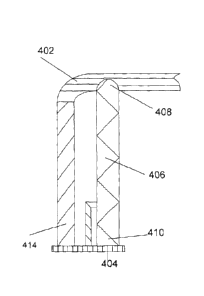
1000231As shown in the embodiment of FIG. 4A and B, the target can be
constructed to fit within
the opening of the goal, the target comprising a first substantially tubular
portion 406, with first
end 410 fitted and attached to base 404 that rests on ice surface 412 and
second end 408
constructed and arranged to receive upper horizontal goal crossbar 402. As
shown in FIG. 4B,
first substantially tubular piece 406 attached to base 404 fits snugly within
the opening of an
official hockey goal, which measures about 48" from ice surface 412 to the
bottom of upper
horizontal goal crossbar 402. The target can be sized so that it does not lift
the goal from ice
surface 412 but is not so short as to become unstable inside the goal opening.
The target may be
in compression between crossbar 402 and ice surface 412. First substantially
tubular portion 406
8
CA 02876678 2014-12-22
may be made of metal tubing with an outer diameter between about 1" and 4",
with a preferred
outer diameter between about 2 1/2" and 3". First substantially tubular
portion 406 may also be
constructed in multiple sections of different outer diameters so that it
telescopes to facilitate
easier transport and storage or to accommodate different goal heights (FIG.
5). In this
embodiment, each section, 502, 504, and 506, can be secured in an extended
position, for
example, by a pin 510, a set screw 512, a cuff or a flange. In some
embodiments, one or more
portions, 504, 506, and 508, may include threaded or unthreaded holes therein
for receiving pins
or set screws.
1000241 In some embodiments, the first substantially tubular portion may be
made out of
materials of sufficient strength to withstand repeated hits from a hard
projectile moving at a
velocity in excess of about 50 mph. Materials include, for example, metals,
polymers and/or
alloys. These can include, but are not limited to, stainless steel, aluminum,
steel, PVC,
polycarbonate and fiberglass reinforced plastic. In many embodiments, the
material provides an
audible sound when the puck hits the first substantially tubular portion so
that a player and others
has notice that the shot has hit its target. The first substantially tubular
portion can be solid or
hollow. The first substantially tubular portion wall thickness can be varied
to, for example,
provide a different tone at different locations on the target or to facilitate
easier LISC. A hollow
construction may decrease the weight of the target, improve acoustics and
facilitate easier
handling. A specific sound can also be engineered by placing a second or even
a third tube inside
the first tubular portion. The diameter of the first substantially tubular
portion may be such that a
number of different diameter cylindrical horizontal crossbars can be seated
across the top of the
second end of the first substantially tubular portion. The exterior of the
first substantially tubular
9
CA 02876678 2014-12-22
portion may be painted, powder coated, rubber coated, treated with a weather
resistant coating or
treated by any other method suitable for protecting or improving the
aesthetics of the material.
100025] As shown in the embodiment of FIG. 6A and 6B, second end 606 of
substantial tubular
portion 604 may be yoke shaped so that an upper cylindrical horizontal
crossbar 602 may fit into
and be held in place by second end 606. Second end 606 may have an inner
diameter of between
about 2" and 4", with a preferred inner diameter between about 2 1/2" and 3"
(FIG. 6B). Second
end 606 may be closed or open. An open second end 606 may permit the use of
sand, foam water
or like material inside first substantially tubular portion 604 to increase
stability and to vary the
pitch of the sound created in a filled portion compared to an empty portion of
first substantially
tubular portion 604. In one embodiment (FIG. 6B), yoke shaped cap 608 may be
attached to
second end 606. Cap 608 may be attached to second end 606 by welding, gluing,
friction fit or
by any other method suitable for attaching second end material to cap
material. Pin 610 may be
attached to the top of cap 606 so that crossbar 602 can be attached to second
end 606, stabilizing
second end 606 within the goal. Second end 606 and cap 608 may be coated with
a protective
material such as a rubberized material, plastic or any material adequate to
protect upper
horizontal goal crossbar 602 and second end 606. In another embodiment (FIG.
7), first
substantially tubular portion 702 may be attached to upper horizontal goal
crossbar 708, for
example, by clamp 704 and pin 706, by hook and loop fastener, tape or any
other suitable
binding device.
100026] In the embodiment of FIG. 8A and 8B, base 800 of the target is fitted
and attached to the
first end of the first substantially tubular portion 802. Base 800 can be
constructed of plate 808,
supportive brace 806 and second tubular portion 804. First substantially
tubular portion 802 and
base 800 may be of similar or dissimilar materials. The exterior of base 800
may be finished in a
CA 02876678 2014-12-22
similar manner to first substantially tubular portion 802. Base 800 may be
attached to the first
substantially tubular portion 802 by welding 810, gluing, friction fit or any
other method suitable
for attaching the first substantially tubular portion material to the base
material. The connection
may be permanent or temporary. Plate 808 can be constructed in such a way as
to accommodate
brace 806, second tubular portion 804 and first substantially tubular portion
802. Corners of plate
808 may be rounded so as not to extend beyond vertical goal post 812. Brace
806 may be
constructed using a right angle configuration, connecting plate 808 to first
substantially tubular
portion 802 in a perpendicular configuration or any other configuration that
provides vertical
support to first substantially tubular portion 802 when target is in an
upright position. Brace 806
may be fabricated of a material that can maintain the first substantially
tubular portion's
perpendicular position relative to the plate. Brace 806 may be attached to
plate 808 by welding,
gluing, or any other method suitable for attaching brace material to plate
material. Second
tubular portion 804 may be hollow so that a sleeve is formed into which a
bottom end of vertical
goal post 812 can be seated, second tubular portion 804 having an opening to
accommodate a
goal base and netting, or it may be solid or hollow so that the end of
vertical goal post 812 fits
over second tubular portion 804. In The base may be coated with a plastic or
rubber to prevent
damage to any skate blades that may come in contact.
[000271 In one embodiment (FIG. 8A and 813), the outer diameter of second
tubular portion 804
may be slightly smaller, between about 1 3/4" and 2 3/8", than the inner
diameter of vertical goal
post 812, creating a snug fit between the outer wall of second tubular portion
804 and the inner
wall of vertical goal post 812 when the goal post is placed over second
tubular portion 804.
Second tubular portion 804 may be conical in shape to help guide vertical goal
post 812 over
second tubular portion 804. A threaded hole may be drilled through brace 806
through which set
11
CA 02876678 2014-12-22
screw 816 can be threaded and tightened against vertical goal post 812,
stabilizing vertical goal
post 812 against second tubular portion 804. A wing nut 818 may be attached to
the inside of
brace 806 to further stabilize set screw 816. In another embodiment, the inner
diameter of second
tubular portion 804 is slightly larger than the outer diameter of vertical
goal post 812, creating a
snug fit between the inner wall of second tubular portion 804 and the outer
wall of vertical goal
post 812 when the goal post is placed inside second tubular portion 804. In
this embodiment,
second tubular portion 804 may include an opening to accommodate the goal base
and netting
when vertical goal post 812 is placed within second tubular portion 804.
Second tubular portion
804 may be attached to the base by welding, gluing, or any other method
suitable for attaching
the second substantial tubular portion material to the plate material so that
a tight and permanent
joining is made. The cross section of second tubular portion 804 can take the
same or different
shape as first substantially tubular portion 802 and may be of sufficient
diameter, between about
1" and 4" OD, to accommodate a variety of vertical goal posts.
[00028] In the embodiment of FIG. 9A and 9B, first substantially tubular
portion 902 may also be
fitted to base 900 by fitting and attaching flange 904 to base 900 over which
first substantially
tubular portion 902 sits (FIG. 9A). First substantially tubular portion 902
may also seat in flange
904 (FIG. 9B). First substantially tubular portion 902 may be permanently
attached to flange
904. First substantially tubular portion 902 may be removable from base 900 to
facilitate ease of
handling and transport. In this embodiment, the downward pressure exerted by
the upper
horizontal goal crossbar on first substantially tubular portion 902 and the
upward pressure
exerted by the ice surface on base 900 provide the needed vertical force to
place the target in
compression and stabilize first substantially tubular portion 902 and base 900
within the opening
of the goal. In the embodiment of FIG. 9B. the outer diameter of first
substantially tubular
12
CA 02876678 2014-12-22
portion 902 may be slightly smaller than the inner diameter of flange 904,
creating a snug fit
between the outer wall of first substantially tubular portion 902 and the
inner wall of flange 904
when first substantially tubular portion 902 is placed inside flange 904. In
the embodiment FIG.
9A, the inner diameter of first substantially tubular portion 902 is slightly
larger than the outer
diameter of flange 904, creating a snug fit between the inner wall of first
substantially tubular
portion 902 and the outer wall flange 904 when first substantially tubular
portion 902 is placed
over flange 904.
1000291 In FIG. 10, first substantially tubular portion 1006 may be suspended
from upper
horizontal goal crossbar 1002 by suspension system 1012. Suspension system
1012 can be made
of hook and loop tape, rubber or any other type of binding device. First
substantially tubular
portion 1006 can be stabilized within the goal opening by attaching first
substantially tubular
portion 1006 to vertical goal post 1008 with fastener 1004 that can be, for
example, a hook,
clamp or binding. First substantially tubular portion1006 may hang freely,
without a base. In one
embodiment, the base may be removable from first substantially tubular portion
1006. In another
embodiment (FIG. 7), first substantially tubular portion 702 may be suspended
from upper
horizontal goal crossbar 708 by clamp 704 and pin 706.
1000301Another embodiment is illustrated in FIG. 11 where a dampening band
1104 may be used
to isolate the pitch of the sound generated by different areas of
substantially tubular portion 1100
when hit, allowing the player and others to establish in which area the target
was hit.
Substantially tubular portion 1100 may be comprised of different segments,
1102 and 1106,
further comprised of different materials. Dampening band 1104 may be made of
rubber, plastic
or any other material which has the required acoustical dampening
characteristics. Segments
1102, 1106 and dampening band 1104 may be of different lengths and/or shapes.
In one
13
CA 02876678 2014-12-22
embodiment, segments 1102 and 1106 may be attached to dampening band 1104, for
example,
by use of pins 1108 or set screws. In one embodiment, dampening band 1104 may
be constructed
so that lower portion 1110 and upper portion 1112 may fit snugly within
segments 1102 and
1106 and so that middle portion 1114 may have an outer diameter similar to
segments 1102 and
1106. In some embodiments, dampening segment 1104 and segments 1102 and 1106
may
include threaded or unthreaded holes therein to receive pins 1108 or set
screws.
10003111n another embodiment, illustrated in FIG. 12, third tubular portion
1201 may be fitted
over first substantially tubular portion 1202 to create a unique tone at a
specific location along
first substantially tubular portion 1202, giving notice to the player and
observers that the puck hit
the location. Third tubular portion 1201 may have an inner diameter between
about 2 3/8" to 3"
so that third tubular portion 1201 can move freely along the outer surface of
first substantially
tubular portion 1202, allowing the player to practice shooting at a chosen
location along the
practice target. Third tubular portion 1201 may be composed of a material that
produces a tone
when struck by a projectile such as, for example, steel, aluminum, stainless
steel, fiberglass
reinforced plastic and polycarbonate. The length of third tubular portion 1201
may be determined
by the skill of the player such that an advanced player is presented with a
short target, for
example between 6" to 12" long, while a novice player is presented with a long
target, for
example between 12" to 18" long. Third tubular portion 1201 may be secured in
a desired
location by, for example, at least one set screw 1203 or pin. Third tubular
portion 1201 may
include threaded or unthreaded holes therein to receive pins or set screws
1203.
1000321 In another embodiment, the target may be connected to an electronic
device that records
hits and provides an auditory as well as a visual indication that a player's
shot was accurate. The
target may be attached to the goal by any of the foregoing methods.
14
CA 02876678 2014-12-22
1000331 While several embodiments of the present invention have been described
and illustrated
herein, those of ordinary skill in the art will readily envision a variety of
other means and/or
structures for performing the functions and/or obtaining the results and/or
one or more of the
advantages described herein, and each of such variations and/or modifications
is deemed to be
within the scope of the present invention. More generally, those skilled in
the art will readily
appreciate that all parameters, dimensions, materials, and configurations
described herein are
meant to be exemplary and that the actual parameters, dimensions, materials,
and/or
configurations will depend upon the specific application or applications for
which the teachings
of the present invention is/are used. Those skilled in the art will recognize,
or be able to
ascertain using no more than routine experimentation, many equivalents to the
specific
embodiments of the invention described herein. It is, therefore, to be
understood that the
foregoing embodiments are presented by way of example only and that, within
the scope of the
appended claims and equivalents thereto, the invention may be practiced
otherwise than as
specifically described and claimed. The present invention is directed to each
individual feature,
system, article, material, kit, and/or method described herein. In addition,
any combination of
two or more such features, systems, articles, materials, kits, and/or methods,
if such features,
systems, articles, materials, kits, and/or methods are not mutually
inconsistent, is included within
the scope of the present invention.
1000341All definitions, as defined and used herein, should be understood to
control over
dictionary definitions, definitions in documents incorporated by reference,
and/or ordinary
meanings of the defined terms.
[00035i The indefinite articles "a" and "an," as used herein in the
specification and in the claims,
unless clearly indicated to the contrary. should be understood to mean -at
least one."
CA 02876678 2014-12-22
[000361The phrase "and/or," as used herein in the specification and in the
claims, should be
understood to mean "either or both" of the elements so conjoined, i.e.,
elements that are
conjunctively present in some cases and disjunctively present in other cases.
Other elements
may optionally be present other than the elements specifically identified by
the "and/or" clause,
whether related or unrelated to those elements specifically identified, unless
clearly indicated to
the contrary.
[000371All references, patents and patent applications and publications that
are cited or referred
to in this application are incorporated in their entirety herein by reference.
16