Note: Descriptions are shown in the official language in which they were submitted.
CA 02876698 2014-12-31
METHOD FOR ENHANCED HYDROCARBON RECOVERY USING IN-SITU RADIO
FREQUENCY HEATING OF AN UNDERGROUND FORMATION WITH
BROADBAND ANTENNA
Field of the Invention
The present invention relates to enhanced hydrocarbon recovery methods, and
more particularly
to the use of electromagnetic (EM) energy in the recovery of subsurface
hydrocarbons.
.Baekground of the Invention
Heavy oil is a term commonly applied to describe oils having a specific
gravity less than about
20' API. These oils, which include oil sand bitumen, are not readily
producible by conventional
techniques. Their viscosity is so high that the oil cannot easily be mobilized
and driven to a
production well by a pressure drive. Therefore, a recovery process is required
to reduce the
viscosity and then produce the oil.
Thermal recovery methods as applied in heavy oil have the common objective of
accelerating the
recovery process. Raising the temperature of the host formation reduces the
heavy oil viscosity,
allowing the near solid material at original temperature to flow as a liquid.
It is known in the art
of 'hydrocarbon recovery, and particularly in the recovery of heavy- and
unconventional
hydrocarbons tiorn subsurface reservoirs, to employ the use of steam or steam-
solvent mixtures
as injectants to reduce, the viscosity of the hydrocarbons and allow them to
flow to a producing
well and thereby be produced to surface. For example, cyclic steam stimulation
(CSS) and
steam-assisted gravity drainage (SAGD) methods employ stemi to mobilize
subsurface heavy
hydrocarbon such as heavy oil or bitumen. However, the effectiveness of steam
injection
methods is limited in most cases to about a 2500 ft. depth. At such depth,
heat losses in surface
steam lines and in the wellbore reduce the steam quality to a value generally
insufficient to
provide the high heat ratio at the reservoir required for an economical oil
flow rate. These oils
are often produced as emulsions with water by using common recovery
techniques.
- -
CA 02876698 2014-12-31
There are certain other situations where steam injection rnay not work well.
These situations can
include the following:
= "Thin pay-zones, where heat losses to adjacent (non-oil-bearing)
formations may bc
significant.
= Low permeability :formations, where the injected fluid may have
difficulty penetrating
deep into the reservoir.
= Reservoir heterogeneity, where high permeability streaks or fractures may-
cause early
injected fluid breakthrough and reduce the sweep.
It has long been recognized that such recovery methods can be costly to
implement and operate
and requires access -to significant water resources. Alternative methods have
accordingly been
developed that employ electromagnetic heating techniques, in which antennae
are positioned
downhole adjacent a target reservoir and generate electromagnetic energy to
heat and thereby
mobilize the heavy hydrocarbons, enabling production to surface.
Electromagnetic (EM) heating has been considered as a viable alternative to
steam-based thermal
processes since electrical instruments are widely available and its use
requires a minimal surface
presence, so it is particularly favorable in populated areas or in offshore
sites. EM heating is a
thermal process, which may be applied to a well to increase its productivity
by the removal of
thennal adaptable skin effects and the reduction of oii viscosity near the
well bore. Electric
current leaves the power supply and is conducted down by the power delivery
system
(transmission line) to the antenna assembly for the radio frequency (RE) case.
The antenna is an
electrical device that can radiate the EM energy into the reservoir formation.
EM-thennal processes are generally understood to be free of issues related to
very low initial
formation injectivity, poor heat transfer, shale layers between rich oil
layers, cap rock
requirement, and the difficulty of controlling the movement of injected fluids
and gases, all of
which have -impacted other thermal recovery processes such as SAGD. Apart from
these, EM-
thermal recovery is also commonly understood to present the following
advantages when
compared with other recovery technologies:
= Heat is generated in-situ.
- 2 -
CA 02876698 2014-12-31
= it does not need a working fluid.
= It does not need a significant water supply.
= It can reduce the produced water cut.
= It is independent of formation permeability.
= There is no apparent depth limit.
= There is no emission concern.
= There are no hazardous chemical concerns.
= It increases apparent permeability.
= it appears to be cost competitive to steam .flood for shallow reservoirs
and less expensive
for deep reservoirs.
= It heats uniformly and near-instantaneously from within and therefore is
independent of
the low thermal conductivity of the torm.ation.
= It increases the pressure and energy or the formation prior to production
While it is commonly held that electromagnetic heating techniques may show
promise in certain
applications, it is believed that improvements and enhancements may be
possible and render
such methods even more desirable. In particular, issues arise with the use of
antennas, and
optimization may be possible.
Summary of the Invention
The present invention therefore seeks to provide a method for enhanced
hydrocarbon recovery
incorporating the use of one or more broadband antennas.
According to a first broad aspect of the present invention, there is provided
a method for
recovering hydrocarbon from a subsurface formation, the method comprising the
steps of:
a. drilling at least one well into the formation adjacent -the hydrocarbon;
b. positioning at least one antenna in the at least one well, the at least
one antenna
operable over a wide frequency bandwidth;
c. emitting electromagnetic energy from the at least one antenna into the
fOrmation;
- 3 -
CA 02876698 2014-12-31
d.
allowing the electromagnetic energy to heat the hydrocarbon and reduce the
viscosity of- the hydrocarbon: and
c. producing the heated hydrocarbon to surface.
In some exemplary embodiments, the at least one antenna can be at least one
broadband antenna,
at least one wideband antenna, or at least one frequency independent antenna.
The
electromagnetic, energy is preferably in the radio frequency range, and most
preferably in a lower
part of the radio frequency range.
The at least one antenna may comprise a plurality of antennae in an array, and
the array inay' be
configured to direct the electromagnetic energy in a direction determined hy
at least one
beamforming algorithm.
Some exemplary methods comprise the further steps after step e of: switching
the at least one
antenna from a high-power heating mode to a low-power transceiver mode:
receiving data
regarding lOnnation characteristics using the at least one antenna; and
transmitting the data using
the at least one antenna. Such exemplary methods may further comprise the step
of using the
data to tune die at least one antenna and direct the electromagnetic energy.
According to a second broad aspect of the present invention, there is provided
a method for
improving an electromagnetic-thermal hydrocarbon recovery process employing at
least one well
in a formation adjacent a hydrocarbon, the method comprising the steps of:
a.
positioning at least one antenna in the at least one well, the at least one
antenna
operable over a wide frequency bandwidth;
b. emitting electromagnetic energy from the at least one antenna into the
formation;
c. allowing the electromagnetic energy to heat the hydrocarbon and reduce
the
V1 scosity of the hydrocarbon;
d. producing the heated hydrocarbon to surface; and
e. allowing the antenna to compensate for impedance mismatch with variable
electrical impedance of the formation during production.
- 4 -
CA 02876698 2014-12-31
According to a third broad aspect of the present invention, there is provided
a method for
improving, an electromagnetic-thermal hydrocarbon recovery process employing
at least one well
in a formation adjacent a hydrocarbon, the method comprising the steps of
a. calculating a post-desiccation impedance change in the tbrmation near
the at least
one well;
b. applying at least one coat of dielectric material to at least onc
antenna to match
the calculated post-desiccation impedance change;
e. positioning the at least one antenna irl th.c at least one well;
d. emitting electromagnetic energy from the at least one antenna into the
formation;
e. allowing the electromagnetic energy to heat the hydrocarbon and reduce
the
viscosity of the hydrocarbon; and
t. producing the heated hydrocarbon to surface.
The method may comprise the application of a single layer of dielectric
material to the at least
one antenna, or a plurality of -layers.
According to a fourth broad aspect of the present invention, there is provided
a method for
recovering hydrocarbon from a subsurface formation, the method comprising the
steps of:
a. drilling at least one well into the tbrmation adjacent the hydrocarbon;
b. calculating a post-desiccation impedance change in the formation near
the at least
one well;
c, applying at least one coat of dielectric material to at least one
antenna to match
the calculated .post-de.siccation impedance change;
d. positioning the at least one antenna in the at least one well;
= e. emitting electromagnetic energy from the at least one antemm into
the tbrmation;
l. allowing the electromagnetic energy to heat the hydrocarbon and reduce
the
viscosity of the -hydrocarbon; and
g. producing the heated hydrocarbon to surface.
According to a CI fib broad aspect of the present invention, there is
provided a system for
recovering; hydrocarbon from a subsurface formation, the system comprising:
- 5 -
CA 02876698 2014-12-31
at least one production well drilled into the forrnation adjacent the
'hydrocarbon;
at least one electromagnetic energy application well drilled into the
formation; and
at lea.st one antenna in the at least one electromagnetic energy application
well, the at
least one antenna operable over a wide frequency bandwidth;
wherein the. at least one antenna is operable to emit electromagnetic eneri-2-
y into the
formation to heat the hydrocarbon and reduce the viscosity of the hydrocarbon;
and
wherein the heated hydrocarbon is produced to surface through the at least one
production well.
A detailed description of exemplary embodiments of the present invention is
given in the
following. ft is to be understood, however, that the invention is not to be
construed as being
limited to these embodiments.
Brief Description of the Drawinas
In the accompanying drawings, which illustrate exemplary embodiments of the
present
invention:
Figure 1 is a sitnplified illustration of an antenna array in accordance with
an
embodiment of the present invention;
Figure 2 is an example of a dipole antenna;
Figure 3 is an ill-ustration of electric field intensity- as a function of
azimuthal angle; and
Figure 4 is a flowchart of a method according to an embodiment of thc present
invention.
Exemplary embodiments of the present invention will now be described with
reference to the
accompanying drawings.
- 6 -
CA 02876698 2014-12-31
Detailed Description of Exemplary .Ernbodiments
Throughout the following description specific details are set forth in order
to provide a more
thorough understanding to persons skilled in the art. However, well known
elements may not
have been shown or described in detail to avoid unnecessarily obscuring the
disclosure. The
following description o examples of the invention is not intended to be
exhaustive or to limit the
invention to the precise 'forms of any exemplary embodiment. Accordingly, the
description and
drawings arc to be regarded in an illustrative, rather than a restrictive_
sense.
The exemplary embodiments arc directed to thc radio frequency (RF) range of EM
heating,
although other ranges of EM energy may be applicable. In the radio frequency
range, the
electrical resistivity and permittivity of a formation are first measured to
select the proper
frequency of the EM source and design the antennas' spacing in reservoir. One
exemplary
aspect of the present invention measures and images the characterization of a
reservoir during the
RE-thermal recovery process to better tune the antenna energy beam and
frequency for efficient
heating process, as will be described below.
The fundamental mechanism of electromagnetic heating involves electric
conduction and/or
dielectric polarization. Electric conduction (quantified by conductivity (-7 -
Sim) is the basis for
Joule heating, also known as ohmic heating and resistive heating, by which the
passage of an
electric current through a conducting medium releases heat. In a polarization
mechanism, polar
molecules or ions oscillate under the effect of an oscillating electromagnetic
field, which
produces heat.
An important factor that needs to be taken into account during an
electromagnetic thermal
process is the skin effect. .Expon.ential decreasing of EM wave penetration
into materials is
known as skin effect. Th.e choice of the electromagnetic source frequency in
an EM themial
process is a compromise between fast heating (greater heat rate) and depth of
penetration,
usually for non-dispersive materials, the lower the frequency the deeper the
EM waves penetrate
in the reservoir.
- 7 -
CA 02876698 2014-12-31
The low frequency EM heating of a reservoir directly depends on the continuous
conductive path
fi.lr electric current between electrodes, meaning that the reservoir water
should always be in a
liquid phase state, especially around the electrodes. Under this circumstance,
based on the skin
effect, a high frequency EM source can only heat up the close vicinity of the
source due to large
values for the loss properties of a water-saturated formation and consequently
less depth of
'penetration. 011 the other hand, if the area around the EM source is dry, low
frequency heating is
not practical, and instead, high frequency EM waves (such as microwaves) can
propagate
through water-free reservoir regions and transfer the energy to a remote area.
In this regard, a
Medi= frequency EM source can benefit from advantages of both low and high
frequency
sources where electric conduction and dielectric polarization mechanisms may
contribute in the
heating process. In a reservoir, such a medium frequency source (for example,
the lower part of
the radio frequency band) can result in joule heating until the vapor chamber
is tOrmed and can
provide dielectric heating after water evaporation.
The ability to use EM energy as part of in situ heavy oil production depends
upon a number of
factors that include: the presence of water; initial formation temperature;
EIVI energy propagation
through the formation; impedance matching and dielectric breakdown within the
formation; and
changes in the dielectric response of materials at different applied
frequencies. Knowledge of
the .frequency-specific dielectric response of the formation will allow for
optimization of process
parameters for pay-zone identification and recovery. Water and minerals
present in the
formation can affect EM energy absorption by the reservoir. Both pore water
saturation and
mineral-bound water, in addition to mineral content, ean affect the measured
dielectric properties
of the formation. At low temperatures, dielectric properties remain
constant at higher
frequencies, although the amount of EM energy absorbed by the tbrmation is
related to its
organic content. Tile geometry of organics and inorganics within the
formationireservoir can
also affect dielectric heating techniques. Dielectric properties differ in
heated and non-heated
samples, as shown by temperature dependent effects on measured dielectric
properties. As a
result, all these factors and physical parameters have to be considered during
dielectric
measurement in a formation. In fact, one of the potential applications of EM
heating antennas
could be EM dynamic (real-time) characterization of the formation while
heating, as described
below.
- 8 -
CA 02876698 2014-12-31
According to a first embodiment of the present invention, one or morc
broadband (or wideband)
antennae, or insulated antennae, are used during RF-therm.al recovery of
hydrocarbon present in
subsurface formations.
Due to reservoir heterogeneity before and during thermal recovery, the
electromagnetic
properties of the fomiation arc continually changing. This results in the
electrical impedance of
the reservoir varying over time. For an RF antenna to have the maximum
radiation efficiency,
however, the impedance of the antennae (which is normally fixed and related to
its fixed
operating frequency) should be matched to the reservoir. The initial
electrical impedance of the
reservoir changes as its temperature rises, and hence an impedance mismatch
between the
antenna and the reservoir occurs, and therefore conventional antennae can fail
quickly if applied
to the RF heating process of a reservoir. This impedance mismatch or imbalance
can then result
in poor radiation efficiency and consequently the total low power efficiency.
According to this aspect of the present invention, broadband antennas are used
to address this
problem. These types of antennae can operate at a wide frequency bandwidth.
The bandwidth of
an antenna is defined as the range of frequencies within which the performance
of the antenna,
with respect to some characteristic, conforms to a specified standard. The
bandwidth can be
considered to be the range of frequencies on either side of a center frequency
(usually the
resonance frequency for a dipole), where the antenna characteristics (such as
input impedance,
pattern, beam-width, polarization, side lobe level, gain, beam direction, and
radiation efficiency)
are within an acceptable value of those at the center .frequency. For
broadband antennas, the
bandwidth is usually expressed as the ratio of the upper-to-lower frequencies
of acceptable
operation. For example, a 10:1 bandwidth indicates that the upper frequency is
10 times greater
than the lower. Therefore, by using a broadband antenna., at each heating
cycle when the
frequency is matched to impedance of the reservoir, the performance of the
antenna remains
acceptable.
The bandwidth is usually formulated in tenns of beam-width, side lobe level,
and pattern
characteristics. Antennas with very large bandwidths (for example 40:1 or
greater) have been
- 9 -
CA 02876698 2014-12-31
designed in recent years. These are known as frequency independent antennas.
There are
different types of broadband antennas that could be considered tbr use with
the present
invention, including for example folded-dipoles, insulated (coated)
dipole/loops, helix, and
traveling-wave antenna., as would be known to those skilled in the art.
According to another aspect of the present .invention, the impedance mismatch
problem may be
addressed by using insulated antennae. First, reservoir characteristics are
determined by
conventionai means, and then it is calculated how the reservoir impedance
would likely change
after desiccation of the reservoir (which would oceur to at least some extent
adjacent the antenna
due to the RE-therrnal heating process), as impedance is affected primarily by
water. Then, a
dielectric (single or multi-layer) coating is applied on the antenna of
interest to match its
impedance to the calculated impedance (for desiccation conditions) of the part
of the fbrmation
located in the vicinity of the antenna. Thus, where there is no production
from the wellbore
housing tile antenna and a state of desiccation or near-desiccation is
achieved around the
antenna, a potentially permanent impedance match can be achieved in which the
radiation
efficiency does not decay. In this case, single frequeney operation can be
carried out and the
need for periodic cyclic frequency tuning is min.imized or potentially
eliminated, reducing the
cost and complexity of the system.
It is also known in the art to use so-called beamforming algorithms to direct
or steer the EM
energy to a desired portion of the reservoir or formation, as the target area
may shift during
recovery operations. According to another aspect of the present invention,
then, an antennae
array system tbr a smart RIF-thermal recovery process is disclosed. By
applying a system of
antennae in array and using standard beamforming algorithms knoi,vii. to those
skilled in the art, it
has been determined that it is possible to direct a beam of radiated
electromagnetic ener1.1.y
toward the hydrocarbon zone to have a more energy-efficient recovery process,
as is illustrated
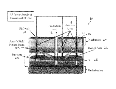
in Figure t. In Figure 1, an exemplary system 10 is illustrated having a
production well 12 and a
plurality of EM wells 14 drilled through overburden 20 into a pay zone 22. The
EM wells 14 are
each provided with a plurality of antennae 16 making up the array IS. The
antenna array 18
produces a field pattern beam 24 to generate a heated zone 26, which heated
zone 26 includes the
target oil 28.
-10 -
CA 02876698 2014-12-31
The an-ay of antennae 18 could be constructed from any type of antennae
applicable to RF-
thermal recovery (including broadband antennae as disclosed above, although it
will be clear that
other types of antennae could be used). The antennae may be placed in either
horizontal or
vertical wellbores. The antenna array may be also in I-dimensional
configuration (lined up on a
straight line in a wellbore, horizontal or vertical), 2-dimensional
configuration (deployed in
multiple wellbores, horizontal or vertical, where all the wellbores are
located on the same
geometrical plane), and 3-dimensional configuration (deployed in multiple
wellbores, horizontal
or vertical, where the wellbores are not located on the same geometrical
plane). A higher
dimension of array configuration yields more flexibility in adjusting the beam
of the energy, at
the expense of more cost and greater complexity_
From the reflection and transmitted signals, it is also possible to develop a
real-time imaging
algorithm to follow the dynamic change of the reservoir and aim the beam of RF
energy to the
area in the subsurface formation that needs to be heated to mobilize the
target hydrocarbon.
Note that in Figure 1 the oil 28 is housed within the heated zone 26 and is
therefore also 'being
heated. It is also within the scope of the present invention to arrange the
process to be automated
and carried out through so-called "smart" and computerized systems, as would
be within the
knowledge of those skilled in the art having regard to the within teaching.
Any suitable types of RF radiators may be used with any aspect of this
invention, such as linear,
loops, slots, coils, and helical, based on the employed frequency range of
operation.
'Io explain the workflow of designing the beam of 1F energy directed to the
area of interest in a
reservoir -forrnation, a Hertzian dipole is taken into account as an example
ancl for simplicity, as
illustrated in Figure 2.
The radiating electromagnet field components in spherical coordinates of such
antenna is given
by
- 11 -
CA 02876698 2014-12-31
ii-IT ii
Er i ___ = 7 coso ( 1
1 + _) e -pa-
-N) e 2fur j kr
To. kit . 1 1
E0 = j ,j¨ ¨ sin() (1 + ,
= 4Irr j kr (kr)2) e- ikr
k I I 1
Ng) = j ¨sirth (1 + 7,¨) e-i
itnr kr
j kr
(1)
where j = V-1 and
k = wv5;i:
E = E0( Ei ¨ .1('Err +
tow
(2)
where w, Ro õ E0 , E' ¨ lE" . a, are the angular frequency, magnetic
penneability of vacuum,
electrical permittivity of vacuum, relative complex permittivity of reservoir,
and electrical
conductivity of reservoir, respectively. If the dipole antenna is placed at a
different location in
the global coordinate system, i.e., (.1:, yi, zi) , then the proper coordinate
transformation should
be applied to obtain the FM- tield values at the reference system.
Assuming no coupling between the array elements, the total electric field
radiated by N-element
antenna array is given by
N
Etot 1 == IE(i)eif?
1=1
(3)
where A is the phase shill of each element's excitation power. The phases can
be set so that the
maximum amplitude of lE0t0/1 occurs at a particular space angle(0, co), as
shown schematically
in Figures l and 2. while Figure 3 illustrates electric field intensity as a
function of azimuthal
angle. This can be done using various optimization techniques such as least
square method,
which is a common practice in wireless telecommunication systems. Such beam
steering can
focus the energy to the area that needs to be heated up rather than radiation
of EM energy in all
directions.
- 12 -
CA 02876698 2014-12-31
As embodiments of the present invention would also benefit from real-time
information on the
reservoir during recovery, another aspect of the present invention involves
switching the
antennae used to heat the reservoir to use as a transceiver to provide
information on
petrophysical characteristics of the reservoir. RF-ther-mal recovery is a very
dynamic process
and reservoir properties vary as the heating process and hydrocarbon
production are taking place.
It is therefore advantageous to obtain information characterizing the changing
reservoir in real
time.
The same antenna (or array of antennae) that is being used to heat the
reservoir (in either vertical
or horizontal wellbores) is switched to low-power mode and employed to send
and receive
electromagnetic measuring signals (which would be at multi-frequencies when
broadband
antennae are used as described above-) through which reservoir electrical
properties can be
calculated using standard inversion algorithms known to those skilled in the
art, similar to
techniques used in cross-well electromagnetic imaging or electromagnetic
impedance
tomography, also known to those skilled in the art.
Unlike the prior art, embodiments of the present invention may incorporate
temperature
information into the inversion algorithm of EM measured through the multi-
physics phenomenon
of a coupled electromagnctic-"thennal fluid flow in porous medium" scheme thus
potentially
improving the accuracy and convergence of the inversion results. The
temperature data may be
gathered from thermal sensors install.ed in an RE well, production well or
monitoring well.
Similar to other tomography processes, the more measured data that is
provided, the more
accurate the results which can be obtained. Other reservoir and production
information (if
available, such as reservoir transient pressure) may be added to thc inversion
process to further
improve the algorithm.
The updated reservoir characteristics can then be utilized to tune the power,
frequency and
possibly the beam direction of the EM energy (when smart antennae are employed
as described
above) to improve the efficiency of the recovery process.
- 13 -
CA 02876698 2014-12-31
Physics of multi-phase fluid-tlos,v and radio frequency electromagnetic wave
propagation
phenomena in porous media ean be coupled by means of appropriate equations,
which
incorporates the dependency of electrical properties of the reservoir
formation (such as electrical
resistivity and dielectric permittivity) on temperature and fluid saturation.
Thus, a multi-physics
inversion algorithm .for the quantitative joint interpretation of geo-
electrical and flow-related
measurements can be formulated to yield an estimation of the underlying
petrophysical model of
thc reservoir formation.
For the multi-physics imaging, time-lapse (multi-snapshot) electromagnetic
measurements of
transmitted and reflected EM signals are conducted at multiple receiver
locations (antenna array
elements placed in vertical andlor horizontal -wellbores), and multiple -
frequencies at low power
mode. Also, multi-probe measurements of reservoir pressure and temperature are
acquired to be
used in the inversion and imaging algorithm.
Joint inversion of the underlying petrophysical model is posed as an
optimization problem that
involves the minimization ()fan objective function subject to physical
constraints. The following
objective function can be adopted for this purpose, known to those skilled in
the art:
C(x) = ki(11Wd = e(x)11 ¨ x2) + lfWx = ¨ x)112
(4)
frt the above expression, we define the vector of residuals, e(x), as a vector
whosepth element is
the residual error (data mismatch.) of the j-th measurement. The residual
error as the difference
between the measured and predicted normalized responses, is given by
e(x) = [(Si (x) ¨ m1), , (S( x) ¨ mm)fr = S(x) ¨ m
(5)
In the above expression, M is the number of measurements, ni; denotes the
normalized observed
response (measured data), and Si corresponds to the normalized simulated
response as predicted
by the vector of model parameters, x, given by
- 14 -
CA 02876698 2014-12-31
X = EX-1, XNIT = Y YR
(6)
where N is the number of unknowns. The vector of model parameters, x, is
represented as the
difference between the vector of the actual model parameters, y, and a
reference model, yle. All a
priori information on the model parameters such as those derived from
independent
measurements are provided by the reference model. The scalar factor, i.e., (0
< /2 < co) is a
regularization parameter tor determining the relative importance of the two
terns of the
objective function. The choice of p produces an estimate of the model x that
has a finite
minimum-weighted nonn away from a prescribed model, x , and which globally
misfits the data
to within a prescribed value x determined from a priori estimates of noise in
the data. The
second term in the objective function is included to regularize the
optimization problem. This
term suppresses magnification of errors in the parameter estimation due to
measurem.ent noise.
The matrix Wx.rW, is the inverse of the model covariance matrix that
represents the degree of
confidence in the prescribed model, xiõ and WaTIV,t is the inverse of the data
covariance matrix
describing the estimated uncertainties in the data, i.e., due to noise
contamination. In the
inversion algorithm the vector of measurements, m, is constructed with two
categories of data:
(a) multi-probe formation temperature and pressure measurements as a function
of time, and (b)
multi-receiver, 111111ti-frequency, and multi-snapshot (time-lapse) EM
reflection measurements.
If desired, the described algorithm can also be used for single-data-type
inversions.
Also, as the energy beam of the antenna array is directed toward the area of
interest in the
reservoir formation., adaptive beamforming algorithms can be well applied Ibr
this purpose,
which are commonly used in telecommunication systems, known to those skilled
in the art.
An exemplary process 30 is illustrated in Figure 4. The process 30 begins with
the RF tool or
other source (which may be the broadband antenna described above) operating at
step 32 in high-
power RF mode. At step 34, this RF energy is applied to the reservoir to heat
the reservoir.
Once this is completed, at step 36 the R.F tool or source is switched to low-
power operation, and
at step 38 this is used to measure thc reservoir characteristics. With this
infbrmation, the RF
- 15 -
CA 02876698 2014-12-31
system can be tuned at step 40 and the antenna's -beam can be steered as
desired. This series of
steps can be repeated as appropriate.
As will be clear from the above, those skilled in the art would be readily
able to detcnnine
obvious variants capable of providing the described functionality, and all
such variants and
functional equivalents arc intended to fall within the scope of the present
invention_
Specific examples have been described herein for purposes of illustration.
These are only
examples. The technology provided herein can be applied to contexts other than
the exemplary
contexts described above.
Many alterations, modifications, additions, omissions and
permutations are possible within the practice of this invention. This
invention includes
variations on described embodiments that would be apparent to the skilled
person, including
variations obtained by: replacing features, elements and/or acts with
equivalent features,
elements and/or acts; mixing and matching of features, elements and/or acts
from different
embodiments; combining features, elements and/or acts from embodiments as
described herein
with features, elements and/or acts of other technology; and/or omitting
combining features,
elements and/or acts from described embodiments.
The foregoing is considered as illustrative only of the principles of the
invention. The scope of
the claims should not be limited by the exemplary embodiments set forth in the
foregoing, but
should be given the broadest interpretation consistent with the specification
as a whole.
- 16 -